EP0109826A2 - Anordnung zur Ableitung medizinischer Daten - Google Patents
Anordnung zur Ableitung medizinischer Daten Download PDFInfo
- Publication number
- EP0109826A2 EP0109826A2 EP83307000A EP83307000A EP0109826A2 EP 0109826 A2 EP0109826 A2 EP 0109826A2 EP 83307000 A EP83307000 A EP 83307000A EP 83307000 A EP83307000 A EP 83307000A EP 0109826 A2 EP0109826 A2 EP 0109826A2
- Authority
- EP
- European Patent Office
- Prior art keywords
- housing
- signal
- detector
- light
- electro
- Prior art date
- Legal status (The legal status is an assumption and is not a legal conclusion. Google has not performed a legal analysis and makes no representation as to the accuracy of the status listed.)
- Withdrawn
Links
Images




Classifications
-
- A—HUMAN NECESSITIES
- A61—MEDICAL OR VETERINARY SCIENCE; HYGIENE
- A61B—DIAGNOSIS; SURGERY; IDENTIFICATION
- A61B5/00—Measuring for diagnostic purposes; Identification of persons
- A61B5/02—Detecting, measuring or recording for evaluating the cardiovascular system, e.g. pulse, heart rate, blood pressure or blood flow
- A61B5/024—Measuring pulse rate or heart rate
- A61B5/02416—Measuring pulse rate or heart rate using photoplethysmograph signals, e.g. generated by infrared radiation
-
- A—HUMAN NECESSITIES
- A61—MEDICAL OR VETERINARY SCIENCE; HYGIENE
- A61B—DIAGNOSIS; SURGERY; IDENTIFICATION
- A61B5/00—Measuring for diagnostic purposes; Identification of persons
- A61B5/103—Measuring devices for testing the shape, pattern, colour, size or movement of the body or parts thereof, for diagnostic purposes
- A61B5/11—Measuring movement of the entire body or parts thereof, e.g. head or hand tremor or mobility of a limb
- A61B5/113—Measuring movement of the entire body or parts thereof, e.g. head or hand tremor or mobility of a limb occurring during breathing
- A61B5/1135—Measuring movement of the entire body or parts thereof, e.g. head or hand tremor or mobility of a limb occurring during breathing by monitoring thoracic expansion
-
- A—HUMAN NECESSITIES
- A61—MEDICAL OR VETERINARY SCIENCE; HYGIENE
- A61B—DIAGNOSIS; SURGERY; IDENTIFICATION
- A61B7/00—Instruments for auscultation
- A61B7/02—Stethoscopes
- A61B7/04—Electric stethoscopes
Definitions
- This invention relates to a system for deriving medical information which is useful in diagnostic, therapeutic and/or preventive medical procedures.
- the stethoscope was the instrument which probably was the most influential in establishing physical examination as a keystone of diagnosis and which started the trend towards objective types of diagnostic therapy.
- the stethoscope merely consisted of a rolled tube of paper, one end of which was placed on the patient's chest and the other in the physician's ear. The sound is conducted by a column of air. Frequency response (or filtering) is accomplished by varying the pressure of the stethoscope bell on the skin or by using a plastic diaphragm.
- a very recent improvement of the original stethoscope involves the use of an audio amplifier for doctors with deficient hearing or for group teaching.
- the stethoscope nevertheless remains a highly effective diagnostic tool in the hands of a skilled physician, as it is responsive, portable, reliable and non-invasive.
- an object of the invention to provide systems for deriving medical information which have adequate or improved sensitivity, accuracy and reliability, are economic to manufacture and maintain, and can be effectively utilised by personnel of relatively limited medical experience and/or training.
- a system for deriving medical information from physical changes in at least one of a plurality of body organs comprising electro-optical sensor means for detecting these physical changes and for generating sensor-output electrical signals responsive to these changes;signal-conditioning means for conditioning the sensor output signals, including means for rejecting interfering components thereof; and signal-processing means for processing the conditioned signals, including, if required, correlating the processed , signals with external data, to provide said medical information.
- Embodiments of the invention can be specially adapted for use in non-invasive procedures while other embodiments can be effectively employed in invasive procedures with improved reliability, sensitivity and safety.
- the invention is, in particular, applicable to systems for making plethysmographic measurements (such as, for example, velocity or volume of blood flow and changes in size of organs or limbs); to auscultatory systems for deriving cardiovascular information; to systems for deriving orthopedic information; and to systems for deriving other medical information such as fluid intake-outflow (renal) function, in-bed weighing and infant activity and condition.
- plethysmographic measurements such as, for example, velocity or volume of blood flow and changes in size of organs or limbs
- auscultatory systems for deriving cardiovascular information to systems for deriving orthopedic information
- other medical information such as fluid intake-outflow (renal) function, in-bed weighing and infant activity and condition.
- medical information means and includes information which is useful in diagnostic, therapeutic and/or preventive medical procedures.
- physical change(s) means and includes a change or rate of change in any of the physical characteristics of a body organ or group of body organs, such as change or rate of change in dimension(s), shape, weight, location and the like.
- body organs means and includes any portion of the human or other animal organism having specialised use or function, such as, without limitinq the generality thereof, for example, the brain, heart, eye, ear, nose, tongue, lung, kidney, stomach, intestine, pancreas, gall bladder, liver, penis, womb, endocrine organs, skin, muscles, the skeletal frame including the axial and appendicular skeleton, osseous processes, exo-skeleton and endoskeleton, blood vessels, as well as, in certain applications of the systems of the present invention, all other components including body fluids which - contribute to the size, shape or weight of the body or any group of body organs, as defined above.
- the term “electro-optical sensor” means and includes a sensor device which senses and/or measures the physical changes in a body organ by optical means and which converts the optical indication or measurement to an electrical signal, one or more components of which contain in "raw” form the data which are necessary to yield (after appropriate processing, buffering and, if required, correlation with external data) the desired medical information.
- the electro-optical sensor includes sensors and related peripherals such as those disclosed in issued U.S.A. patents Nos.
- electro-optical sensor also includes other combinations of light sources, optical components such as lenses, filters and mirrors, and light detectors which are sensitive to linear motion and insensitive to angular deflection or which function to measure other structurally related phenomena, including, for example, angular deflection, angular displacement, strain and shear phenomena.
- the electrical output of the sensor can be fed directly to external peripherals, such as the raw signal-conditioning circuitry and data-processing units.
- external peripherals such as the raw signal-conditioning circuitry and data-processing units.
- the signal-conditioning and/or data-processing components of the system can be combined with the sensor in a unitary package for implantation along with suitable means, e.g., a low power RF transmitter, contained within the package to communicate the conditioned and/or processed signal containing the desired medical information to an external receiver for display, recording/editing or control purposes.
- the term "external input(s)" means and includes data in the form of electrical signals usable in the processing of the sensor output signals or components thereof for correlation with the sensor- derived data to yield the desired medical information.
- the mother's heartbeats measured by a similar sensor is utilized along with techniques such as cross-correlation and adaptive noise cancellation to isolate the fetal heartbeat from the background noise.
- the nominal or normal circumference of the organ may be entered as I external input to determine medical external input to determine medical information as to deviation and/or trend of the circumference change.
- Fig. 1 depicts in block flow diagram form the general mode of operation of systems embodying the invention.
- a physical change in a body organ constitutes an input 10 to an electro-optical sensor or array thereof 11.
- the sensor output is an electrical signal 12 which is suitably processed and buffered by signal-conditioning means 13 to modify the information content of the signal 12, for example, by rejectinq unwanted components or isolating selected components which form the input 14 to analog-to-digital conversion circuitry 16.
- the digitized signal 16 together with external inputs 17 (e.g., on-off signals, gain, comparative or nominal data), if any, is manipulated by a suitable data-processing computer 18 (e.g. a microprocessor).
- the output 19 of the data-processing is manipulated by a suitable data-processing computer 18 (e.g. a microprocessor).
- the unit 18 forms the input 19a to data-recording and editing units 20, the input 19b to data-display equipment 21 and/or the input 19c to control systems 22.
- the output of the data-processing unit 18 may be fed sequentially to the data-recording and editing unit 20 and to the data-display unit 21, the outputs 23 and 24 of which yield directly usable medical information 25 reflecting the condition, location, etc., of the body organ as inferred or directly measured from the physical changes 10 thereof.
- the system of Fig. 1 includes as a major subcomponent, a structural information detector combining the optical sensor of the system with at least certain of the associated electronic signal processing circuits.
- Figure 2 illustrates the structural information detector 30 in block form, the detector being depicted for purposes of illustration as being mounted upon a support structure 31 which, as explained below, is specially adapted and shaped and/or sized as required by the particular type of medical information to be derived.
- the structural information detector 30 consists of a housing 32, an optical sensor 33, sensor power supply 34, raw signal conditioning/conversion circuitry 34c and signal processing electronics including a microprocessor and appropriate software 35.
- the optical sensor 33 preferably a structural moment detector (sometimes also known as a "flexural rigidity sensor") of the type generally disclosed in issued U.S. patent N o.' 4,287,511, and in U.S. patent application Serial No. 265,031 measures, as indicated by the dashed line 33a, the relative orientation of surface _ coordinate vectors which are, as illustratively depicted in Fig. 2, normals 36 to the surface 31a of the beam 31.
- a force F (37) is applied in the direction of the arrow 37a to the beam 31, resultant bending of the beam 31 will cause a change in the relative orientation of the surface coordinate vectors 36 to the positions indicated by the dashed lines 36a, i.e., from the angular orientation 38 e1 (shown in Fig. 2, illustratively, as 180°) to an angular orientation 38a ⁇ 2 which (as illustratively depicted in Fig. 2) is greater than 61.
- Power 39 from an external power source 39a is supplied to the circuitry 34 which, as explained below, provides a regulated power supply to the optical sensor 33.
- the raw data 33b from the optical sensor 33 which could be a variable voltage or a variable current, is supplied to the raw signal conversion portion 34c of the circuitry, which converts the raw data, as will be further explained below, to a form suitable for feeding to the input 34b of the signal and data-processing electronics and software 35.
- the unit 35 processes the converted signal 34b and provides, as the output 35a of the structural moment detector 30, a signal which directly indicates the effect of the force F acting on the beam 31 and thereby embodying useful medical information 40.
- the useful information 40 can be utilised in any or all of a variety of ways, i.e., it can be used as the input to a direct display 40b which may be a simple galvanometric meter, liquid crystal display, light emitting diode display, cathode ray tube or the like. Also or alternatively, the useful information 40 can be used as the input to a semi-permanent or permanent recording device 40c, such as paper recorders, magnetic recorders, semiconductor storage devices, optical recorders, bubble memory storage devices, or holographic storage devices. Also or alternatively, the useful - information 4.0 can form the input to various control devices 40d such as servomotors and other similar electromechanical devices.
- a direct display 40b which may be a simple galvanometric meter, liquid crystal display, light emitting diode display, cathode ray tube or the like.
- the useful information 40 can be used as the input to a semi-permanent or permanent recording device 40c, such as paper recorders, magnetic recorders, semiconductor
- the raw data output 33b of the optical sensor 33 constitutes the input to the signal conversion/ conditioning electronics 41, 43 (Fig. 3).
- the function of the circuitry 41, 43, depicted in Fig. 3 is to convert and condition the raw data input 33b from the optical sensor into data suitable for electronic data processing and then to feed this data to processing electronics 43 (including computational software) to perform the data-processing function to yield a signal, the components of which directly provide useful medical information.
- the signal conversion/conditioning is performed with analog electronics, rather than digital.
- the analog electronics perform two distinct functions. First, the output current into 13b from the optical sensor is converted to a proportional voltage in a transimpedance amplifier.
- circuit 41 which, for clarity of illustration, are those components which are located within the dashed line 41.
- the second function is to amplify "the proportional voltage signal from circuit 41 by feeding it through a gain control 42 into an amplifier which, for purposes of clarity of description, are those components located within the dashed line 43.
- Circuit 41 operates as a short circuit load for the photovoltaic cells of the optical sensor. Feedback is added in the amplifier circuit 43 to shape the upper end of the frequency response so that spurious high frequency noise is attenuated.
- This function is performed by applying the output of IC1 (pin 7) to the input (pin 6) of IC2 through a voltage divider formed by R7-R8. Ie2 acts as a low-pass filter.
- the output of IC2 (pin 7) is fed back through R16 to the input 3 of IC1 to act as an automatic bias adjustment.
- An offset voltage adjustment is provided to remove any bias due to photocell mismatch.
- the gain control 42 provides a means of balancing the mechanical gain of different sensors and compensating for components variation.
- the nominal adjustment range is +15%.
- the amplifier 43 is a high gain direct- coupled amplifier with capacitive feedback to further attenuate high frequency noise levels. Nominal gain is 1.5 volts/microamp and the bandwidth is normally initially set at 50-500 Hz.
- Support and bias circuits which include the components which are, for clarity of illustration, enclosed within the dashed line 44,condition power and bias voltages for the components of the circuit 41 and 43.
- the output 46 of the amplifier 43 is an analog signal which is converted to a digital signal in the A-D converter 42a.
- a non-limiting, illustrative, example of a suitable analog-digital converter is manufactured by the U.S. firm Analog Devices under No. HAS1202.
- the signal-processing electronics 45 converts the output signal 42b of the A-D converter 42a into electrical signals 40 which directly provide data related to the effect of the force acting on the structure to which the structural information detector is attached.
- this component includes a microprocessor, appropriate computational software, the necessary supporting devices and a power supply, details of which are omitted for purposes of clarity because they are well-known to those skilled in the art. Suitable non-limiting examples of microprocessors which can be employed are the TI9000 or the Intel 8086.
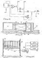
- the power supply circuitry 34 (Fig.2) for supplying a precise current to a light emitting diode of the optical sensor 33 is shown schematically in Fig. 4.
- the 15 volt supply is provided by the support and bias circuitry 44 of Fig. 3.
- the power supply circuitry of Fig. 4 utilizes two amplifiers in a high gain feedback arrangement to provide the necessary precise current 52 to the light emitting diode.
- All of the elements described in Figs. 3 and 4 may be fabricated on a printed circuit board using standard integrated circuits or on a single thick film substrate where the circuits have been wire bonded to the substrate.
- the structural information detector shown in Figure 5 consists of a first housing sub-assembly generally indicated by reference character 60 containing the sensor power supply/raw signal conversion/signal-processing , electronics 61 of Figs. 3-4, a light emitting diode 62, a pair of photovoltaic detectors 63 and a collimating lens 64 carried proximate the open end of a barrel portion 65 formed in the housing sub- ". assembly 60.
- a second housing sub-assembly generally indicated by reference numeral 66, carries a plane surface mirror 67 on the inner end 68 of a mating barrel portion 69 formed in the housing sub-assembly 66.
- a substantial clearance 70 is shown between the barrel portion 65 formed in the first housing sub-assembly 60 and the barrel portion 69 formed in the second housing sub-assembly 66, it will be understood by those skilled in the art that this clearance is shown only for the purpose of clarifying the mechanical relationship of the two housing sub-assemblies 60 and 66.
- the mating barrel portion 69 formed in the second housing sub-assembly 66 is shaped and dimensioned to receive the barrel portion 65 formed in the first housing sub-assembly 60 with an interference fit therebetween, to form a unitary structurally integrated device which excludes ambient light from the interior of the barrel portions 65 and 69 and which facilitates and assists in maintaining precise optical alignment of the two sub-assemblies.
- the two housing sub-assemblies 60 and 66 are securely fixed to a member at spaced locations therealong so that any bending of this member serves to vary the alignment of the mirror 67 relative to the optical axis of the assembly 60, this variation causing a differential change in the amount of light reaching the detectors 63.
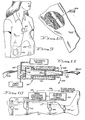
- the structural information detector shown in Figure 5 is suitable for use in medical-information systems such as will be - described hereinafter with reference to Figures 13 to 15.
- FIG. 6 shows a second embodiment of the optical sensor 33, this sensor being constructed as a stethoscope and including a housing portion 161 having a flared open-ended skirt portion 162, shaped and dimensioned to be placed against the patient's body in the manner of a conventional stethoscope bell.
- An annular internal slot 163 formed in the inner surface of the housing 161 carries a flexible diaphragm 164, the upper surface 165 of which is silvered to be light- reflective.
- Light emanating from the LED 166 passes through the collimating lens 167 and is reflected as shown by the dashed lines to the photo-voltaic cell 168.
- the diaphragm 164 is arranged to move in dependence on a physical change being monitored whereby to vary the output of the cell 168.
- the output of the photovoltaic cell 168 is supplied to signal-conditioning electronics 169.
- the power supply and signal-processing/amplification electronics 170 furnish outputs to a data display 171, data recording unit 172, a digital output 173, and head phones 174.
- the stethoscope can be provided with a polygonal mirror, hinged on one side to permit angular displacement of the mirror surface with respect to a pair of photocells in a manner analogous to the sensor of Fig. 5.
- a third embodiment of the optical sensor is depicted in cross-section in Fig. 11.
- the sensor generally indicated by the reference character 210, includes a hollow body portion 216 having a light source (LED) 217 and photovoltaic cells 218 carried by the . internal face 219 of a closed end 220.
- a hollow piston member 221 is received within the hollow portion of the body member 216 and extends through aperture 222 which is sized to permit movement of the piston 221 in the axial direction 223 and in the transverse directions 224 and 225. Outward axial movement of the member 221 is resisted by a compression spring.
- Attachment straps 226 and 226a are affixed, respectively, to the closed end 220 of the body portion 216 and to the outer end of the piston member 221.
- the senor shown in Figure 6 can be used,with the associated electronics there shown,directly as a stethoscope (see Fig. 7), the power supply and electronics 170 being housed in a belt-mounted package and furnishing outputs via lines 53a, 54a, 55a to the units 171 to 174.
- an array of the stethoscope bells can be semi-permanently attached to a patient's chest to provide semi-continuous phonocardiogram data.
- the data-recording unit 172 can be included together with the power supply and the signal-processing/amplification electronics 170, in a belt-mounted package 181 to provide a completely mobile system.
- the system can also be employed to detect and locate vascular occlusions by locating an array of sensors around the area of the suspected blockage and manipulating the outputs by triangulation techniques to characterise and locate the actual blockage.
- the system of the present invention can be utilised to provide semi-continuous monitoring and/or recording of fetal heartbeat.
- separate stethoscope bells 201 and 202 are placed, respectively, as shown to receive the maternal heartbeat (201) and the fetal heartbeat (202).
- the maternal heartbeat received from the bell 201 is fed to data processing- recording/editing circuitry contained in an external package 203.
- the monitored "physical change" (in this case, fetal heartbeat) from the stethoscope bell 202 is also fed to the data processing-recording /editing circuitry contained in the package 203 and manipulated in such fashion as to isolate the fetal heartbeat from the background noise of the mother's heartbeat by known techniques, such as cross-correlation and adaptive noise cancellation.
- Fig. 10 illustrates an embodiment of the present invention which performs non-invasive plethysmographic measurements and utilises a plurality of optical sensors 210 of the Figure 11 form.
- These sensors 210 are attached at spaced points along a portion of the body such as the leg 211.
- the outputs 212 of the sensors 210 indicate changes in circumference of the,body member and are fed to signal-conditioning and processing electronics 213. If desired, nominal circumferences at each of the spaced points can also be entered from a keyboard 214 and manipulated along with the signals 212 to provide data 215 for display, recording, audio amplification, etc.
- plethysmographic measurement such as increase in circumference of blood vessels can also be'made, for example, as schematically illustrated in Fig. 12, in which a cuff 231 is surgically implanted around the femoral artery 232.
- the cuff 231 contains not only an electro-optical sensor, but also a miniaturized transmitter which emits radio signals which are received by an external receiver 234. Lead wires are not normally employed in this application to transmit the signal from the cuff 231 to external data processing-signal recording/editing circuitry in order to avoid the risk of infection.
- Orthopedic medical information can be derived from physical changes in body member according to the embodiments such as those illustrated in Figs. 13-14.
- the changes in bone composition and/or strength can be measured and monitored by attaching optical sensors 241 (for example, of the Figure 5 form) at spaced points along a bone, for example, the tibia 242. Striking the bone 242 with a mallot 243 or by some other calibrated method of applying a known force, causes flexure of the bone 242 which is sensed by the electro-optical sensors 241, the outputs 244 of which are fed to signal-conditioning and processing circuitry 245. The data is compared with nominal bone composition and/or strength characteristics or with prior signals to provide the desired medical information 246 which is fed to data-display 247, data-recording 248 or further data-conversion 249 (such as a computer).
- optical sensors 241 for example, of the Figure 5 form
- the amount and effect of a therapeutic force 251 applied to an extremity such as the leg 252 can be measured by an electro-optical sensor 253 which yields therapeutic force data output 254, which may either be displayed or applied to control circuitry 255 to actually vary the therapeutic force 251 to achieve a desired degree of bending of the leg 252.
- FIG. 14 Yet another application of the system of the present invention is also depicted in Fig. 14.
- This system can also be used to derive other types of medical data. For example, by continuously monitoring the weight of the patient, fluid intake-output information can be directly and continuously monitored.
- Fig. 15 depicts a system for monitoring the activity and vital signs of an infant 261 in a crib 262 which is provided with an electro-optical sensor 263, the output 264 of which is fed to signal conditioning and processing electronics 265.
- the output 266 of the signal-processing electronics 265 can be displayed and/or recorded and can activate remote alarm systems 267.
- the objective of this system is to continuously provide and/or record the physical condition of the infant and to give suitable alarms in case of malfunctions of the infant's body systems to detect the symptoms of crib death or Sudden Infant Death Syndrome.
Landscapes
- Health & Medical Sciences (AREA)
- Life Sciences & Earth Sciences (AREA)
- Physics & Mathematics (AREA)
- Public Health (AREA)
- Surgery (AREA)
- Veterinary Medicine (AREA)
- General Health & Medical Sciences (AREA)
- Engineering & Computer Science (AREA)
- Biomedical Technology (AREA)
- Heart & Thoracic Surgery (AREA)
- Medical Informatics (AREA)
- Molecular Biology (AREA)
- Animal Behavior & Ethology (AREA)
- Physiology (AREA)
- Pathology (AREA)
- Cardiology (AREA)
- Biophysics (AREA)
- Acoustics & Sound (AREA)
- Dentistry (AREA)
- Oral & Maxillofacial Surgery (AREA)
- Measuring And Recording Apparatus For Diagnosis (AREA)
- Measurement And Recording Of Electrical Phenomena And Electrical Characteristics Of The Living Body (AREA)
- Measuring Pulse, Heart Rate, Blood Pressure Or Blood Flow (AREA)
Applications Claiming Priority (2)
| Application Number | Priority Date | Filing Date | Title |
|---|---|---|---|
| US44246082A | 1982-11-17 | 1982-11-17 | |
| US442460 | 1982-11-17 |
Publications (2)
| Publication Number | Publication Date |
|---|---|
| EP0109826A2 true EP0109826A2 (de) | 1984-05-30 |
| EP0109826A3 EP0109826A3 (de) | 1985-05-15 |
Family
ID=23756865
Family Applications (1)
| Application Number | Title | Priority Date | Filing Date |
|---|---|---|---|
| EP83307000A Withdrawn EP0109826A3 (de) | 1982-11-17 | 1983-11-16 | Anordnung zur Ableitung medizinischer Daten |
Country Status (2)
| Country | Link |
|---|---|
| EP (1) | EP0109826A3 (de) |
| JP (1) | JPS59139236A (de) |
Cited By (3)
| Publication number | Priority date | Publication date | Assignee | Title |
|---|---|---|---|---|
| US4976265A (en) * | 1987-12-23 | 1990-12-11 | Consiglio Nazionale Delle Richerche | Method of detecting enterogastric reflux |
| WO1991011956A1 (en) * | 1990-02-16 | 1991-08-22 | Lindberg Lars Goeran | A monitor which analyses puls frequency by photoplethysmographic measurement and a measuring method therefor |
| GB2250816A (en) * | 1990-11-30 | 1992-06-17 | Ivac Corp | Non-invasive blood pressure sensor using a diaphragm and electro-magnetic radiation |
Families Citing this family (1)
| Publication number | Priority date | Publication date | Assignee | Title |
|---|---|---|---|---|
| DE3724336A1 (de) * | 1987-07-23 | 1989-02-02 | Draegerwerk Ag | Schutzmaske mit eingebautem sensor zur ueberwachung von lebensfunktionen |
Family Cites Families (7)
| Publication number | Priority date | Publication date | Assignee | Title |
|---|---|---|---|---|
| FR540363A (fr) * | 1921-01-18 | 1922-07-10 | Procédé d'auscultation et moyens en permettant la réalisation | |
| US4185239A (en) * | 1976-01-02 | 1980-01-22 | Filloux Jean H | Super sharp and stable, extremely low power and minimal size optical null detector |
| JPS6043134B2 (ja) * | 1977-08-25 | 1985-09-26 | 信紘 佐藤 | 生体の臓器,組識の反射特性測定装置 |
| US4159422A (en) * | 1977-10-26 | 1979-06-26 | Shigeo Okubo | Temperature stable displacement sensor with fine resolution |
| US4287511A (en) * | 1979-10-22 | 1981-09-01 | Scott Science And Technology, Inc. | Intrusion alarm system utilizing structural moment detector as intrusion sensor and as receiver for mechanical intrusion and command signals |
| US4453218A (en) * | 1980-11-24 | 1984-06-05 | Oximetrix, Inc. | Signal filter method and apparatus |
| US4409842A (en) * | 1981-05-18 | 1983-10-18 | Scott Science & Technology, Inc. | Structural information detector |
-
1983
- 1983-11-16 EP EP83307000A patent/EP0109826A3/de not_active Withdrawn
- 1983-11-17 JP JP21706083A patent/JPS59139236A/ja active Pending
Cited By (5)
| Publication number | Priority date | Publication date | Assignee | Title |
|---|---|---|---|---|
| US4976265A (en) * | 1987-12-23 | 1990-12-11 | Consiglio Nazionale Delle Richerche | Method of detecting enterogastric reflux |
| WO1991011956A1 (en) * | 1990-02-16 | 1991-08-22 | Lindberg Lars Goeran | A monitor which analyses puls frequency by photoplethysmographic measurement and a measuring method therefor |
| US5396893A (en) * | 1990-02-16 | 1995-03-14 | Oberg; Ake P. | Method and apparatus for analyzing heart and respiratory frequencies photoplethysmographically |
| GB2250816A (en) * | 1990-11-30 | 1992-06-17 | Ivac Corp | Non-invasive blood pressure sensor using a diaphragm and electro-magnetic radiation |
| GB2250816B (en) * | 1990-11-30 | 1994-09-14 | Ivac Corp | Pressure sensor |
Also Published As
| Publication number | Publication date |
|---|---|
| JPS59139236A (ja) | 1984-08-10 |
| EP0109826A3 (de) | 1985-05-15 |
Similar Documents
| Publication | Publication Date | Title |
|---|---|---|
| US5103832A (en) | Biological pressure transducer zeroing and levelling reference apparatus | |
| US6328698B1 (en) | Diagnostic system and method for coronary artery disease and others | |
| Hinman et al. | Portable blood pressure recorder accuracy and preliminary use in evaluating intradaily variations in pressure | |
| Togawa et al. | Biomedical transducers and instruments | |
| US5111826A (en) | Indirect continuous blood pressure method | |
| US5237997A (en) | Method of continuous measurement of blood pressure in humans | |
| US4991590A (en) | Fiber optic intravascular blood pressure transducer | |
| US6491647B1 (en) | Physiological sensing device | |
| US6030343A (en) | Single beam tone burst ultrasonic non contact tonometer and method of measuring intraocular pressure | |
| US6226547B1 (en) | Catheter tracking system | |
| US7128714B1 (en) | Non-contact waveform monitor | |
| US3841314A (en) | Pulse activity indicator | |
| US20070149883A1 (en) | Method for detecting heart beat and determining heart and respiration rate | |
| JP2019516454A (ja) | 対象上のウェアラブル装置の位置及び向きの少なくとも一方を決定する方法及び装置 | |
| KR20060063962A (ko) | 생체정보 검출장치 및 혈압계 | |
| US3908640A (en) | Cardiovascular instrument | |
| US6099476A (en) | Blood pressure measurement system | |
| WO2008007361A2 (en) | Wearable, ambulatory, continuous, non-invasive blood pressure measuring method and system | |
| Reder et al. | Evaluating indirect blood pressure measurement techniques: a comparison of three systems in infants and children | |
| Peura | Blood pressure and sound | |
| EP0109826A2 (de) | Anordnung zur Ableitung medizinischer Daten | |
| US3585987A (en) | Method for automatic continuous measuring and recording of blood pressure and arrangements for executing said method | |
| Kara et al. | Low-cost compact ECG with graphic LCD and phonocardiogram system design | |
| WO2017030993A1 (en) | Wearable oximeter for respiration measurement and compensation | |
| RU2102922C1 (ru) | Тремометр |
Legal Events
| Date | Code | Title | Description |
|---|---|---|---|
| PUAI | Public reference made under article 153(3) epc to a published international application that has entered the european phase |
Free format text: ORIGINAL CODE: 0009012 |
|
| AK | Designated contracting states |
Designated state(s): AT BE CH DE FR GB IT LI LU NL SE |
|
| PUAL | Search report despatched |
Free format text: ORIGINAL CODE: 0009013 |
|
| AK | Designated contracting states |
Designated state(s): AT BE CH DE FR GB IT LI LU NL SE |
|
| STAA | Information on the status of an ep patent application or granted ep patent |
Free format text: STATUS: THE APPLICATION IS DEEMED TO BE WITHDRAWN |
|
| 18D | Application deemed to be withdrawn |
Effective date: 19861202 |
|
| RIN1 | Information on inventor provided before grant (corrected) |
Inventor name: STOCKHAM, LEO W. Inventor name: SCOTT, DAVID R. |