EP0110084A1 - Elément de distribution électrique - Google Patents
Elément de distribution électrique Download PDFInfo
- Publication number
- EP0110084A1 EP0110084A1 EP83110298A EP83110298A EP0110084A1 EP 0110084 A1 EP0110084 A1 EP 0110084A1 EP 83110298 A EP83110298 A EP 83110298A EP 83110298 A EP83110298 A EP 83110298A EP 0110084 A1 EP0110084 A1 EP 0110084A1
- Authority
- EP
- European Patent Office
- Prior art keywords
- plug
- contact
- distribution element
- electrical distribution
- element according
- Prior art date
- Legal status (The legal status is an assumption and is not a legal conclusion. Google has not performed a legal analysis and makes no representation as to the accuracy of the status listed.)
- Granted
Links
- 239000004020 conductor Substances 0.000 claims abstract description 11
- 238000003780 insertion Methods 0.000 claims description 10
- 230000037431 insertion Effects 0.000 claims description 10
- 238000009434 installation Methods 0.000 description 2
- 238000011161 development Methods 0.000 description 1
- 230000018109 developmental process Effects 0.000 description 1
- 238000004519 manufacturing process Methods 0.000 description 1
Images

Classifications
-
- H—ELECTRICITY
- H01—ELECTRIC ELEMENTS
- H01R—ELECTRICALLY-CONDUCTIVE CONNECTIONS; STRUCTURAL ASSOCIATIONS OF A PLURALITY OF MUTUALLY-INSULATED ELECTRICAL CONNECTING ELEMENTS; COUPLING DEVICES; CURRENT COLLECTORS
- H01R31/00—Coupling parts supported only by co-operation with counterpart
- H01R31/02—Intermediate parts for distributing energy to two or more circuits in parallel, e.g. splitter
-
- H—ELECTRICITY
- H01—ELECTRIC ELEMENTS
- H01R—ELECTRICALLY-CONDUCTIVE CONNECTIONS; STRUCTURAL ASSOCIATIONS OF A PLURALITY OF MUTUALLY-INSULATED ELECTRICAL CONNECTING ELEMENTS; COUPLING DEVICES; CURRENT COLLECTORS
- H01R13/00—Details of coupling devices of the kinds covered by groups H01R12/70 or H01R24/00 - H01R33/00
- H01R13/02—Contact members
- H01R13/10—Sockets for co-operation with pins or blades
- H01R13/11—Resilient sockets
- H01R13/111—Resilient sockets co-operating with pins having a circular transverse section
Definitions
- the invention relates to an electrical distributor element according to the preamble of the main claim.
- the connection between the contact sockets on the one hand and the electrical conductors connected to them on the other hand is usually relatively complicated and complex, which leads to greater assembly effort during assembly and does not rule out the possibility that incorrect connections also occur.
- the electrical distribution element according to the invention with the characterizing features of the main claim has the advantage that the electrical connection between the contact sockets and the associated electrical conductors is simple, requires little effort and can be produced quickly, reproducibly and without the risk of incorrect connections when assembling the distribution element can.
- claims 5 and 6 further simplify assembly are achieved in a particularly simple manner; because this specifies the respective location for the contact sockets and their plug-in parts, so that during assembly the individual contacting elements are only to be placed in the respectively assigned receiving chamber and are then correctly positioned there.
- the electrical distribution element 10 shown in the drawing consists e.g. from a header as an element of an installation kit and has a stepped housing with two housing parts 11 and 12.
- the upper housing part 11 in FIG. 1 has an outer housing wall 13 with recessed receptacles 14 and sockets 15 located therein, which are 4-pole here.
- sockets 15 are grouped in a row.
- the sockets 15 are introduced with all individual parts into a plastic body 16 which is integral with the housing part 11.
- a 4-pole plug (not shown) that also matches the contour can be inserted.
- the contact pins engage in individual contact sockets 17 made of electrically conductive material contained in the plastic body 16.
- the other housing part 12 is approximately cap-shaped along the four sockets 15 in the plastic body 16. It overlaps the plastic body 16 like a cap, leaving a lower intermediate space 18.
- the housing part 12 extends in stages and with an essentially plate-shaped part 19, which carries a 7-pin plug 20 here, the contact pins 21 of which are in opposite directions are aligned with the sockets 15.
- the plug 20 can be inserted, for example, into a suitable, 7-pin socket of a plug distributor belonging to the kit, which has several 7- pin sockets of this type. These sockets of the plug distributor are technically designed like the sockets 15.
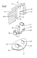
- the contact sockets 17 have a plug-in part 22, connected in one piece and with an electrically conductive connection, with an approximately C-shaped cross section.
- a carrier plate 23 which is common to all sockets 15 and which projects at the individual points assigned to the plug parts 22 in each case in the form of a flat, in the C-shape of the respectively assigned plug contacts 24 Plug part 22 matching tongue carries.
- the carrier plate 23 is in two parts. It has an upper plastic plate 25 and a printed circuit board 26 located underneath, on which the plug contacts 24 are mechanically fixed and electrically conductive. One plug contact 24 is plugged together with one plug part 22.
- the individual plug contacts 24 are connected to electrical conductors running there, which is illustrated by the projecting connection ends 27.
- the electrical conductors can also consist of cables that run in the wiring 18 in the wiring space.
- a flexible conductor strip 28 which is arranged between them and which is guided in a loop 29 to the plate-shaped part 19 and is soldered there to the contact pins 21.
- the individual contact sockets 17 of the sockets 15 are each mechanically and electrically conductively connected to their associated plug part 22 via an essentially S-shaped curved flag 30, which is integral with both.
- the contact socket 17 and the plug part 22 are directed essentially in opposite directions to one another, the contact socket 17 being arranged at one end of the S of the lug 30 and the plug part 22 being arranged at the other end.
- the individual contact sockets 17 with their plug-in parts 22 connected therewith via the lug 30 are each received as a unit within an identical receiving chamber 31 in the plastic body 16 of the housing part 11 and are kept floating therein.
- FIG. 3 shows four such receiving chambers 31, without contact sockets 17 contained therein, with plug-in part 22 connected via lug 30.
- Each receiving chamber 31 has an at least partially circular chamber 32, furthermore an approximately rectangular chamber 33 at a distance and a connecting chamber 34 between the two When plugging in, the circular chamber 32 takes the contact socket 17, the rectangular chamber 33 the C-shaped plug. part 22 and the connecting chamber 34 on the flag 30, in such a way that the complete element is positioned and held in the receiving chamber 31 and thus at the predetermined location.
- the rectangular chamber 33 has an inner, molded step stop 35 which limits the insertion depth of the C-shaped plug-in part 22 and supports the latter in the plug-in direction.
- the approximately circular chamber 32 has a step 37 in its bottom area located at the top in FIGS. 1 and 5, and where the housing wall 13 has insertion openings 36 for the individual contact pins of the 4-pin plug, not shown, a step 37 limiting the insertion depth of the contact socket 17.
- the chamber 32 also contains a further, approximately annular step 38, which sits approximately at the same height as the step stop 35. At step 38, two further bent leg portions 39, 40 separated from the contact socket 17 abut, limiting the insertion depth.
- the carrier plate 23, namely its plastic plate 25, has a small distance laterally next to the plug contact 24 a parallel, protruding and integrally formed support tongue 41.
- an approximately parallel projection 42 is also formed on the plastic plate 25 and is located on the area which is assigned to a contact socket 17. The latter can rest on or on the projection 42 in the region of its facing end, so that the projection 42 also has a supporting function.
- each receiving a contact socket 17 are grouped essentially concentrically around a common center 43, thereby ensuring that the inserted contact sockets 17 run essentially concentrically to the center point 43.
- the explained distributor element 10 has the advantage that it is inexpensive to manufacture and, above all, can be assembled, while at the same time ensuring that the individual contact sockets 17 are mounted at the desired location, concentrically around the center point 43 and at a predetermined distance in the circumferential direction from one another, and at the same time the electrical connection between the contact sockets 17 on the one hand and the electrical conductors of the printed circuit board 26 is made on the other.
- the assembly of the distributor element 10 is therefore particularly simple and scarcely carries the risk of incorrect installation with incorrect connections.
Landscapes
- Connector Housings Or Holding Contact Members (AREA)
- Coupling Device And Connection With Printed Circuit (AREA)
Applications Claiming Priority (2)
| Application Number | Priority Date | Filing Date | Title |
|---|---|---|---|
| DE19823243728 DE3243728A1 (de) | 1982-11-26 | 1982-11-26 | Elektrisches verteilerelement |
| DE3243728 | 1982-11-26 |
Publications (2)
| Publication Number | Publication Date |
|---|---|
| EP0110084A1 true EP0110084A1 (fr) | 1984-06-13 |
| EP0110084B1 EP0110084B1 (fr) | 1986-09-10 |
Family
ID=6179068
Family Applications (1)
| Application Number | Title | Priority Date | Filing Date |
|---|---|---|---|
| EP83110298A Expired EP0110084B1 (fr) | 1982-11-26 | 1983-10-15 | Elément de distribution électrique |
Country Status (2)
| Country | Link |
|---|---|
| EP (1) | EP0110084B1 (fr) |
| DE (2) | DE3243728A1 (fr) |
Cited By (4)
| Publication number | Priority date | Publication date | Assignee | Title |
|---|---|---|---|---|
| GB2157509A (en) * | 1984-03-13 | 1985-10-23 | Black & Decker Inc | Wiring system for mini tools |
| GB2161333A (en) * | 1984-07-06 | 1986-01-08 | Ford Motor Co | Electronics box for motor vehicles |
| EP0379662A3 (fr) * | 1989-01-25 | 1991-08-14 | A. & H. Meyer GmbH Leuchten und Büroelektrik | Boítier de prises |
| EP3793036A1 (fr) * | 2019-09-13 | 2021-03-17 | E.G.O. Elektro-Gerätebau GmbH | Prise de contact, dispositif de carte de circuit imprimé et système enfichable correspondant |
Families Citing this family (1)
| Publication number | Priority date | Publication date | Assignee | Title |
|---|---|---|---|---|
| GB2188497B (en) * | 1986-03-27 | 1990-11-07 | Yazaki Corp | Connector |
Citations (2)
| Publication number | Priority date | Publication date | Assignee | Title |
|---|---|---|---|---|
| DE2022319A1 (de) * | 1969-05-07 | 1970-11-19 | Bulgin Reginald William | Steckerverbindung in einem Verteilersystem fuer elektrischen Strom |
| DE2921991A1 (de) * | 1978-05-30 | 1979-12-13 | Amp Inc | Elektrischer verbindungskasten |
-
1982
- 1982-11-26 DE DE19823243728 patent/DE3243728A1/de not_active Withdrawn
-
1983
- 1983-10-15 EP EP83110298A patent/EP0110084B1/fr not_active Expired
- 1983-10-15 DE DE8383110298T patent/DE3366119D1/de not_active Expired
Patent Citations (2)
| Publication number | Priority date | Publication date | Assignee | Title |
|---|---|---|---|---|
| DE2022319A1 (de) * | 1969-05-07 | 1970-11-19 | Bulgin Reginald William | Steckerverbindung in einem Verteilersystem fuer elektrischen Strom |
| DE2921991A1 (de) * | 1978-05-30 | 1979-12-13 | Amp Inc | Elektrischer verbindungskasten |
Cited By (4)
| Publication number | Priority date | Publication date | Assignee | Title |
|---|---|---|---|---|
| GB2157509A (en) * | 1984-03-13 | 1985-10-23 | Black & Decker Inc | Wiring system for mini tools |
| GB2161333A (en) * | 1984-07-06 | 1986-01-08 | Ford Motor Co | Electronics box for motor vehicles |
| EP0379662A3 (fr) * | 1989-01-25 | 1991-08-14 | A. & H. Meyer GmbH Leuchten und Büroelektrik | Boítier de prises |
| EP3793036A1 (fr) * | 2019-09-13 | 2021-03-17 | E.G.O. Elektro-Gerätebau GmbH | Prise de contact, dispositif de carte de circuit imprimé et système enfichable correspondant |
Also Published As
| Publication number | Publication date |
|---|---|
| EP0110084B1 (fr) | 1986-09-10 |
| DE3243728A1 (de) | 1984-05-30 |
| DE3366119D1 (en) | 1986-10-16 |
Similar Documents
| Publication | Publication Date | Title |
|---|---|---|
| DE3783692T2 (de) | Modulartiger elektrischer verbinder. | |
| EP0445376B1 (fr) | Connecteur | |
| DE69306463T2 (de) | Elektrischer Flachbauverbinder | |
| EP0154930B1 (fr) | Moteur électrique, en particulier moteur d'essuie-glace pour véhicules | |
| DE2835568A1 (de) | Elektrischer verbinder und anschlusselement dafuer | |
| DE2834493A1 (de) | Elektrischer verbinder | |
| DE2426373A1 (de) | Elektrischer verbinder | |
| DE2446081A1 (de) | Elektrische verbinderanordnung | |
| DE9115318U1 (de) | Elektrischer Verbinder mit reduzierter Einführkraft | |
| DE69524935T2 (de) | Abgeschirmte verbinderanordnung | |
| EP0584481B1 (fr) | Borne de connexion multipolaire | |
| DE3928751C2 (fr) | ||
| DE19547557A1 (de) | Elektrische Klemmen mit steckbaren Querbrückern | |
| EP0495778B1 (fr) | Connecteur de filtrage | |
| DE69807411T2 (de) | Kathodenstrahlröhrensockel | |
| EP0211357A2 (fr) | procédé d'installation d'un dispositif de contact sur une carte de circuits imprimés. | |
| DE69213991T2 (de) | Mehrfachkammer-Verbindermodul | |
| DE4312781A1 (de) | Anschlußelement für wenigstens ein elektrisches Betriebsmittel | |
| DE19835606C2 (de) | Abschirm-Steckverbinder | |
| EP0483532B1 (fr) | Dispositifs de connexion pour circuits imprimés | |
| EP0110084B1 (fr) | Elément de distribution électrique | |
| DE69304133T2 (de) | Anschluss eines Erdungsdrahtes an die Abschirmung eines elektrischen Verbinders | |
| DE69603884T2 (de) | Einrichtung zum Montieren einer Lampe | |
| DE2349330A1 (de) | Elektrischer kontakt fuer sicherungshalter | |
| DE3146739A1 (de) | Elektromagnetisches schaltgeraet |
Legal Events
| Date | Code | Title | Description |
|---|---|---|---|
| PUAI | Public reference made under article 153(3) epc to a published international application that has entered the european phase |
Free format text: ORIGINAL CODE: 0009012 |
|
| 17P | Request for examination filed |
Effective date: 19831015 |
|
| AK | Designated contracting states |
Designated state(s): CH DE FR GB IT LI |
|
| GRAA | (expected) grant |
Free format text: ORIGINAL CODE: 0009210 |
|
| AK | Designated contracting states |
Kind code of ref document: B1 Designated state(s): CH DE FR GB IT LI |
|
| ET | Fr: translation filed | ||
| REF | Corresponds to: |
Ref document number: 3366119 Country of ref document: DE Date of ref document: 19861016 |
|
| ITF | It: translation for a ep patent filed | ||
| PLBE | No opposition filed within time limit |
Free format text: ORIGINAL CODE: 0009261 |
|
| STAA | Information on the status of an ep patent application or granted ep patent |
Free format text: STATUS: NO OPPOSITION FILED WITHIN TIME LIMIT |
|
| 26N | No opposition filed | ||
| PGFP | Annual fee paid to national office [announced via postgrant information from national office to epo] |
Ref country code: GB Payment date: 19911001 Year of fee payment: 9 |
|
| PGFP | Annual fee paid to national office [announced via postgrant information from national office to epo] |
Ref country code: FR Payment date: 19911030 Year of fee payment: 9 |
|
| ITTA | It: last paid annual fee | ||
| PGFP | Annual fee paid to national office [announced via postgrant information from national office to epo] |
Ref country code: DE Payment date: 19911227 Year of fee payment: 9 |
|
| PGFP | Annual fee paid to national office [announced via postgrant information from national office to epo] |
Ref country code: CH Payment date: 19920117 Year of fee payment: 9 |
|
| PG25 | Lapsed in a contracting state [announced via postgrant information from national office to epo] |
Ref country code: GB Effective date: 19921015 |
|
| PG25 | Lapsed in a contracting state [announced via postgrant information from national office to epo] |
Ref country code: LI Effective date: 19921031 Ref country code: CH Effective date: 19921031 |
|
| GBPC | Gb: european patent ceased through non-payment of renewal fee |
Effective date: 19921015 |
|
| PG25 | Lapsed in a contracting state [announced via postgrant information from national office to epo] |
Ref country code: FR Effective date: 19930630 |
|
| REG | Reference to a national code |
Ref country code: CH Ref legal event code: PL |
|
| PG25 | Lapsed in a contracting state [announced via postgrant information from national office to epo] |
Ref country code: DE Effective date: 19930701 |
|
| REG | Reference to a national code |
Ref country code: FR Ref legal event code: ST |