EP0110131A1 - Dispositif et méthode de lecture électromagnétique de données de coordonnées - Google Patents
Dispositif et méthode de lecture électromagnétique de données de coordonnées Download PDFInfo
- Publication number
- EP0110131A1 EP0110131A1 EP83110700A EP83110700A EP0110131A1 EP 0110131 A1 EP0110131 A1 EP 0110131A1 EP 83110700 A EP83110700 A EP 83110700A EP 83110700 A EP83110700 A EP 83110700A EP 0110131 A1 EP0110131 A1 EP 0110131A1
- Authority
- EP
- European Patent Office
- Prior art keywords
- conductors
- electromotive force
- cursor
- loops
- axis
- Prior art date
- Legal status (The legal status is an assumption and is not a legal conclusion. Google has not performed a legal analysis and makes no representation as to the accuracy of the status listed.)
- Granted
Links
Images


Classifications
-
- G—PHYSICS
- G06—COMPUTING OR CALCULATING; COUNTING
- G06F—ELECTRIC DIGITAL DATA PROCESSING
- G06F3/00—Input arrangements for transferring data to be processed into a form capable of being handled by the computer; Output arrangements for transferring data from processing unit to output unit, e.g. interface arrangements
- G06F3/01—Input arrangements or combined input and output arrangements for interaction between user and computer
- G06F3/03—Arrangements for converting the position or the displacement of a member into a coded form
- G06F3/041—Digitisers, e.g. for touch screens or touch pads, characterised by the transducing means
- G06F3/046—Digitisers, e.g. for touch screens or touch pads, characterised by the transducing means by electromagnetic means
Definitions
- the present invention relates generally to electromagnetically reading coordinate data to obtain digital equivalents of the data and to a digitizer system having such a function.
- a typical electromagnetic digitizer known heretofore comprises an exciting coil for producing an alternating magnetic field and two mutually perpendicular sets of parallel conductors arrayed like a reticulate lattice.
- the magnetic field induces electromotive forces in the conductors.
- the exciting coil (hereinafter shall be referred to as a cursor coil or simply as a coil) is housed in a cursor or stylus capsule of the digitizer movable along the surface of the lattice.
- the conductors in one set are electrically insulated from the other set of conductors. These conductors are embedded in a planar substrate to form a so-called tablet.
- alternating voltage of tens Hz to several MHz is applied across the coil C housed therein to induce alternating electromotive forces in the respective loops X i and Y j
- the electromotive force is measured by sequentially changing over the switches S x and Sy from the loops X 1 and Y 1 through to X m and Y n , respectively. Then, reading the address or coordinates (x i , y j ) of a pair of one X i and Y. under the highest electromotive force in each set of loops gives the position of the cursor.
- the positional resolution depends on the intervals between adjacent loops or conductors. Therefore, to improve the resolution, the conductors must be arrayed at correspondingly decreased intervals, or positions between adjacent conductors must be determined somehow. However, it is difficult to make the intervals narrower than about 0.5 mm in view of the manufacturing technique and cost or from a quality control aspect. Therefore, if a resolution higher than this level is required, it is necessary to determine such inter-conductor positions by some means or other.
- a few known solutions for determining such inter-conductor positions are described with reference to Figs. 2, 3 and 4.
- Fig. 2 shows typically how the peak value of alternating electromotive force induced in a loop L by a coil C changes as the coil moves transversely of the loop L.
- the diameter d of the coil C is almost equal to the interval between two conductors forming the loop L.
- one known method utilizes such a change in the induced electromotive force with the position of the coil relative to the loop.
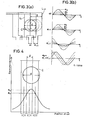
- This method uses a tablet having its alternate conductors connected together at their one ends so that the resultant one set of loops formed of adjacent odd conductors are half-lapped over the other set of loops formed of adjacent even conductors, as shown in Fig. 3(a). If the interval between two conductors forming one loop is almost equal to the diameter of the coil C like the case of Fig. 2, the electromotive forces e. and e i+1 induced in the loops L. and L i+1 will have waveforms as shown in Fig.
- Japanese Patent Provisional Publication No. 52-96825 discloses the use of a coil having a diameter d about three times larger than the interval l between adjacent conductors as shown in Fig. 4.
- the inter-conductor position is determined based on the finding that the ratio e m/ e s of the highest electromotive force e m to the second highest electromotive force e among the three loops substantially covered by the coil C is a function of its inter-conductor position.
- this function is not a linear one, complicated calculation is required, or the positional reading must be compensated by using data precollected and stored in a ROM or the like.
- an object of the present invention is to provide a simplified method of reading coordinates with an improved accuracy, and an apparatus for such method.
- the coordinates namely, the position of the cursor coil is determined based on the distribution of the electromotive forces induced in the conductors of the tablet, the distribution being substantially symmetrical with respect to the center of the cursor coil.
- the method of the present invention permits the inter-conductor positions to be determined more accurately and simplifiedly.
- the present invention employs a digitizer having a cursor coil and a tablet.
- the plane of the tablet substantially represents a rectangular Cartesian coordinate system.
- the X-axial and Y-axial positions of the cursor coil can be determined quite identically, the following description will be made only with regard to the X-axis.
- the cursor coil of d in effective flux diameter produces a magnetic field over the loops arrayed in the tablet at intervals of l.
- a suitable ratio may be selected depending on the resolution desired in specific cases. In the present invention, it is preferred that the ratio ranges from about 10 to 30 (namely, 10l ⁇ d ⁇ 30l) . Of course, this ratio may be smaller than 10.
- E E(x) as shown in Fig. 5.
- the two selected loops on one side of the curve must exist at symmetrical positions to those on the other side or the two loops on each side must correspond to a substantially linear portion of the distribution curve.
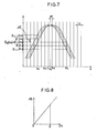
- FIG. 7 there are shown three distribution curves E n (x), E n-1 (x) and E(x) which are obtained substantially in the same manner as the curve of Fig. 5.
- m is a constant which can also be predetermined experimentally.
- ⁇ x may be determined based on the ratio E(x a )/E(x b ) instead of ⁇ E used above.
- m can be predetermined as .Thus, from the formulas (5) and ( 6 ),
- cursor coil and the tablet may be adapted to produce a double-peak distribution curve with each peak occuring at each end of the coil as shown in Fig.
- the distribution curve was obtained by measuring electromotive forces induced by the cursor coil in the loops or the conductors, it may be obtained by measuring the electromotive force induced in the cursor coil by sequentially excited loops or conductors.
- Fig. 11 schematically shows such a digitizer in which the numeral 1 generally denotes conductors arrayed at constant.intervals in a tablet.
- the conductros 1 have their one ends connected together.
- Each group G i is provided with a selector M i which selects at a time at most one conductor from its associated group.
- the selectors M i as a whole function like a multiplexor.
- the outputs of alternate'selectors are connected together to one or the other input terninal of an amplifier AMP. In other words, the even and odd selectors have their outputs connected to one and the other input terminals of the amplifier AMP, respectively.
- a microprocessor MPC sequentially selects a pair of adjacent selectors so that in the selected pair the conductors at the same position are selected.
- the electromotive force induced by a cursor coil in a loop formed of the selected pair of conductors is fed as input to the amplifier AMP. Therefore, when sequentially selecting a pair of adjacent selectors and their conductors, the output of the amplifier AMP will give a distrilution curve of electromotive forces as shown in Fig. 5.
- the output of the amplifier AMP is fed as its peak to the analog-digital converter AD through a sample holding circuit SH. Based on the digital input fed by the converter AD, the microprocessor performs an arithmetic operation to determine the exact position of the cursor coil in accordance with the formula (2) or (3) described previously.
- the microprocessor selects a next pair of adjacent selectors only when all the conductors of the currently selected pair have been subjected to measurement.
- the system may be adapted so that the microprocessor first scans all the selectors through with the respective selectors set at their fixed positions, for example, at their lefmost positions, to permit that the selection of the conductors be started just from such a pair of selectors where the scanning finds induction of a predetermined threshold electromotive force. Then the position of the cursor coil can be determined more efficiently.
Landscapes
- Engineering & Computer Science (AREA)
- Physics & Mathematics (AREA)
- General Engineering & Computer Science (AREA)
- Theoretical Computer Science (AREA)
- Electromagnetism (AREA)
- Human Computer Interaction (AREA)
- General Physics & Mathematics (AREA)
- Measurement Of Length, Angles, Or The Like Using Electric Or Magnetic Means (AREA)
- User Interface Of Digital Computer (AREA)
- Position Input By Displaying (AREA)
Applications Claiming Priority (2)
| Application Number | Priority Date | Filing Date | Title |
|---|---|---|---|
| JP57190344A JPS5979384A (ja) | 1982-10-28 | 1982-10-28 | 座標読取方法 |
| JP190344/82 | 1982-10-28 |
Publications (2)
| Publication Number | Publication Date |
|---|---|
| EP0110131A1 true EP0110131A1 (fr) | 1984-06-13 |
| EP0110131B1 EP0110131B1 (fr) | 1987-01-07 |
Family
ID=16256630
Family Applications (1)
| Application Number | Title | Priority Date | Filing Date |
|---|---|---|---|
| EP83110700A Expired EP0110131B1 (fr) | 1982-10-28 | 1983-10-26 | Dispositif et méthode de lecture électromagnétique de données de coordonnées |
Country Status (4)
| Country | Link |
|---|---|
| US (1) | US4554409A (fr) |
| EP (1) | EP0110131B1 (fr) |
| JP (1) | JPS5979384A (fr) |
| DE (1) | DE3369018D1 (fr) |
Cited By (5)
| Publication number | Priority date | Publication date | Assignee | Title |
|---|---|---|---|---|
| EP0220331A1 (fr) * | 1985-10-24 | 1987-05-06 | Pencept, Inc. | Tablette à numériser comprenant des boucles en forme de "U" en matériau conducteur |
| US4694124A (en) * | 1984-03-23 | 1987-09-15 | Pencept, Inc. | Digitizing tablet system including a tablet having a grid structure made of two orthogonal sets of parallel uniformly sized and spaced U shaped loops of conductive material |
| FR2647240A1 (fr) * | 1989-05-22 | 1990-11-23 | Schlumberger Ind Sa | Table a numeriser |
| EP0427198A1 (fr) * | 1989-11-07 | 1991-05-15 | Summagraphics Corporation | Contrôleur numérique pour dispositif de localisation de position |
| GB2288241A (en) * | 1994-03-31 | 1995-10-11 | Graphtec Kk | Digitizer and position determination method therefor |
Families Citing this family (16)
| Publication number | Priority date | Publication date | Assignee | Title |
|---|---|---|---|---|
| JPS60181816A (ja) * | 1984-02-29 | 1985-09-17 | Pentel Kk | 図形入力装置 |
| US4928256A (en) * | 1988-03-16 | 1990-05-22 | Ametek, Inc. | Digitizer for position sensing |
| US5194699A (en) * | 1990-04-03 | 1993-03-16 | Summagraphics Corporation | Digitizer tablet with fixed incremented grid portions |
| US4996393A (en) * | 1990-04-03 | 1991-02-26 | Summagraphics Corporation | Digitizer tablet with split-current conductor array |
| US5276282A (en) * | 1992-04-15 | 1994-01-04 | International Business Machines | Optimal scan sequence for RF magnetic digitizers |
| JPH05127805A (ja) * | 1992-05-07 | 1993-05-25 | Wacom Co Ltd | 座標値決定方法 |
| EP0574213B1 (fr) * | 1992-06-08 | 1999-03-24 | Synaptics, Inc. | Détecteur de position d'un objet |
| US5861583A (en) * | 1992-06-08 | 1999-01-19 | Synaptics, Incorporated | Object position detector |
| US6028271A (en) * | 1992-06-08 | 2000-02-22 | Synaptics, Inc. | Object position detector with edge motion feature and gesture recognition |
| US5880411A (en) | 1992-06-08 | 1999-03-09 | Synaptics, Incorporated | Object position detector with edge motion feature and gesture recognition |
| US5889236A (en) * | 1992-06-08 | 1999-03-30 | Synaptics Incorporated | Pressure sensitive scrollbar feature |
| US6239389B1 (en) | 1992-06-08 | 2001-05-29 | Synaptics, Inc. | Object position detection system and method |
| US6380929B1 (en) | 1996-09-20 | 2002-04-30 | Synaptics, Incorporated | Pen drawing computer input device |
| US5854625A (en) * | 1996-11-06 | 1998-12-29 | Synaptics, Incorporated | Force sensing touchpad |
| US8050876B2 (en) | 2005-07-18 | 2011-11-01 | Analog Devices, Inc. | Automatic environmental compensation of capacitance based proximity sensors |
| JP4811313B2 (ja) * | 2007-03-23 | 2011-11-09 | セイコーエプソン株式会社 | 位置検出装置、表示装置および情報処理システム |
Citations (4)
| Publication number | Priority date | Publication date | Assignee | Title |
|---|---|---|---|---|
| WO1980001853A1 (fr) * | 1979-02-22 | 1980-09-04 | Summagraphics Corp | Lecteur de coordonnees |
| GB2054300A (en) * | 1979-05-24 | 1981-02-11 | Talos Systems | Digitising the location of a coil |
| GB2080539A (en) * | 1980-07-10 | 1982-02-03 | Seiko Instr & Electronics | Coordinate determining device |
| GB2093299A (en) * | 1981-02-12 | 1982-08-25 | Summagraphics Corp | Digitzers |
Family Cites Families (9)
| Publication number | Priority date | Publication date | Assignee | Title |
|---|---|---|---|---|
| US3647963A (en) * | 1969-03-10 | 1972-03-07 | Bendix Corp | Automatic coordinate determining device |
| US4088842A (en) * | 1975-05-23 | 1978-05-09 | Kabushiki Kaisha Daini Seikosha | Automatic coordinate determining device |
| US4018989A (en) * | 1975-12-24 | 1977-04-19 | Summagraphics Corporation | Position coordinate determination device |
| JPS5510608A (en) * | 1978-07-07 | 1980-01-25 | Kokusai Denshin Denwa Co Ltd <Kdd> | Coordinate reader |
| US4240065A (en) * | 1978-12-13 | 1980-12-16 | Wigmore Professional Data Services Ltd. | Position sensing apparatus |
| US4213005A (en) * | 1978-12-13 | 1980-07-15 | Cameron Eugene A | Digitizer tablet |
| JPS5935069B2 (ja) * | 1979-01-19 | 1984-08-27 | セイコーインスツルメンツ株式会社 | 座標読取装置の補間方式 |
| JPS584382B2 (ja) * | 1979-01-23 | 1983-01-26 | セイコーインスツルメンツ株式会社 | 座標読取装置 |
| US4418242A (en) * | 1980-03-04 | 1983-11-29 | Fujitsu Limited | Coordinate reading apparatus |
-
1982
- 1982-10-28 JP JP57190344A patent/JPS5979384A/ja active Granted
-
1983
- 1983-10-24 US US06/544,701 patent/US4554409A/en not_active Expired - Lifetime
- 1983-10-26 EP EP83110700A patent/EP0110131B1/fr not_active Expired
- 1983-10-26 DE DE8383110700T patent/DE3369018D1/de not_active Expired
Patent Citations (4)
| Publication number | Priority date | Publication date | Assignee | Title |
|---|---|---|---|---|
| WO1980001853A1 (fr) * | 1979-02-22 | 1980-09-04 | Summagraphics Corp | Lecteur de coordonnees |
| GB2054300A (en) * | 1979-05-24 | 1981-02-11 | Talos Systems | Digitising the location of a coil |
| GB2080539A (en) * | 1980-07-10 | 1982-02-03 | Seiko Instr & Electronics | Coordinate determining device |
| GB2093299A (en) * | 1981-02-12 | 1982-08-25 | Summagraphics Corp | Digitzers |
Non-Patent Citations (1)
| Title |
|---|
| NATIONAL TELECOMMUNICATIONS CONFERENCE, 29th November - 3rd December 1981, New Orleans, Louisiana, vol. 4 of 4, pages G5.4.1 - G.5.4.5, IEEE, New York, US * |
Cited By (8)
| Publication number | Priority date | Publication date | Assignee | Title |
|---|---|---|---|---|
| US4694124A (en) * | 1984-03-23 | 1987-09-15 | Pencept, Inc. | Digitizing tablet system including a tablet having a grid structure made of two orthogonal sets of parallel uniformly sized and spaced U shaped loops of conductive material |
| EP0220331A1 (fr) * | 1985-10-24 | 1987-05-06 | Pencept, Inc. | Tablette à numériser comprenant des boucles en forme de "U" en matériau conducteur |
| FR2647240A1 (fr) * | 1989-05-22 | 1990-11-23 | Schlumberger Ind Sa | Table a numeriser |
| EP0427198A1 (fr) * | 1989-11-07 | 1991-05-15 | Summagraphics Corporation | Contrôleur numérique pour dispositif de localisation de position |
| GB2288241A (en) * | 1994-03-31 | 1995-10-11 | Graphtec Kk | Digitizer and position determination method therefor |
| US5670754A (en) * | 1994-03-31 | 1997-09-23 | Graphtec Corp. | Digitizer and position determination method therefor |
| GB2288241B (en) * | 1994-03-31 | 1998-02-25 | Graphtec Kk | Digitizer and position determination method therefor |
| CN1040374C (zh) * | 1994-03-31 | 1998-10-21 | 葛拉天狄克株式会社 | 数字化器及其位置确定方法 |
Also Published As
| Publication number | Publication date |
|---|---|
| JPH0361208B2 (fr) | 1991-09-19 |
| JPS5979384A (ja) | 1984-05-08 |
| EP0110131B1 (fr) | 1987-01-07 |
| DE3369018D1 (en) | 1987-02-12 |
| US4554409A (en) | 1985-11-19 |
Similar Documents
| Publication | Publication Date | Title |
|---|---|---|
| EP0110131A1 (fr) | Dispositif et méthode de lecture électromagnétique de données de coordonnées | |
| US4582955A (en) | Digitizing tablet system including a tablet having a grid structure made of two orthogonal sets of parallel uniformly sized and spaced U shaped loops of conductive material | |
| USRE37490E1 (en) | Electronic caliper using a reduced offset induced current position transducer | |
| EP0152961B1 (fr) | Appareil pour détecteur de position | |
| JPH0643994A (ja) | 高周波磁気ディジタイザのための最適走査シーケンス | |
| EP0181512B1 (fr) | Dispositif de contrôle à courants de Foucault | |
| KR960006091B1 (ko) | 마테우치효과를 이용한 자기검출기 | |
| US4806708A (en) | Coordinate determining device and method of determining X-Y coordinate position | |
| US4694124A (en) | Digitizing tablet system including a tablet having a grid structure made of two orthogonal sets of parallel uniformly sized and spaced U shaped loops of conductive material | |
| JP2003066009A (ja) | 渦流探傷装置 | |
| EP0556852A1 (fr) | Digitaliseur | |
| US12031815B2 (en) | Magnetic linear sensor | |
| JPH0424717A (ja) | ワイヤレス座標読取装置 | |
| US6188217B1 (en) | Inductive measurement device for determining dimensions of objects | |
| JP2653011B2 (ja) | インダクトシン基板 | |
| EP0511027A2 (fr) | Système pour la lecture de coordonnées | |
| SU896378A1 (ru) | Способ измерени линейных и угловых перемещений плоских электропровод щих объектов | |
| JPH04361318A (ja) | 座標読取装置 | |
| JPS6394547A (ja) | 走査電子顕微鏡 | |
| JP2002031546A (ja) | 磁気式エンコーダ | |
| JPH04326418A (ja) | 相対座標読取装置 | |
| JP2625479B2 (ja) | 座標検出装置 | |
| SU1068849A1 (ru) | Способ измерени магнитной индукции в листовой стали и устройство дл его осуществлени | |
| SU792273A2 (ru) | Способ считывани графической информации | |
| JP2002040154A (ja) | 導体の位置探査に用いられる方法と装置 |
Legal Events
| Date | Code | Title | Description |
|---|---|---|---|
| PUAI | Public reference made under article 153(3) epc to a published international application that has entered the european phase |
Free format text: ORIGINAL CODE: 0009012 |
|
| AK | Designated contracting states |
Designated state(s): BE CH DE FR GB IT LI NL SE |
|
| 17P | Request for examination filed |
Effective date: 19840726 |
|
| GRAA | (expected) grant |
Free format text: ORIGINAL CODE: 0009210 |
|
| AK | Designated contracting states |
Kind code of ref document: B1 Designated state(s): BE CH DE FR GB IT LI NL SE |
|
| REF | Corresponds to: |
Ref document number: 3369018 Country of ref document: DE Date of ref document: 19870212 |
|
| ET | Fr: translation filed | ||
| ITF | It: translation for a ep patent filed | ||
| PLBE | No opposition filed within time limit |
Free format text: ORIGINAL CODE: 0009261 |
|
| STAA | Information on the status of an ep patent application or granted ep patent |
Free format text: STATUS: NO OPPOSITION FILED WITHIN TIME LIMIT |
|
| 26N | No opposition filed | ||
| ITTA | It: last paid annual fee | ||
| EAL | Se: european patent in force in sweden |
Ref document number: 83110700.8 |
|
| PGFP | Annual fee paid to national office [announced via postgrant information from national office to epo] |
Ref country code: GB Payment date: 19990831 Year of fee payment: 17 |
|
| PGFP | Annual fee paid to national office [announced via postgrant information from national office to epo] |
Ref country code: FR Payment date: 19990917 Year of fee payment: 17 |
|
| PGFP | Annual fee paid to national office [announced via postgrant information from national office to epo] |
Ref country code: SE Payment date: 19991021 Year of fee payment: 17 Ref country code: CH Payment date: 19991021 Year of fee payment: 17 |
|
| PGFP | Annual fee paid to national office [announced via postgrant information from national office to epo] |
Ref country code: BE Payment date: 19991022 Year of fee payment: 17 |
|
| PGFP | Annual fee paid to national office [announced via postgrant information from national office to epo] |
Ref country code: NL Payment date: 19991027 Year of fee payment: 17 |
|
| PGFP | Annual fee paid to national office [announced via postgrant information from national office to epo] |
Ref country code: DE Payment date: 19991215 Year of fee payment: 17 |
|
| PG25 | Lapsed in a contracting state [announced via postgrant information from national office to epo] |
Ref country code: GB Free format text: LAPSE BECAUSE OF NON-PAYMENT OF DUE FEES Effective date: 20001026 |
|
| PG25 | Lapsed in a contracting state [announced via postgrant information from national office to epo] |
Ref country code: SE Free format text: THE PATENT HAS BEEN ANNULLED BY A DECISION OF A NATIONAL AUTHORITY Effective date: 20001030 |
|
| PG25 | Lapsed in a contracting state [announced via postgrant information from national office to epo] |
Ref country code: LI Free format text: LAPSE BECAUSE OF NON-PAYMENT OF DUE FEES Effective date: 20001031 Ref country code: CH Free format text: LAPSE BECAUSE OF NON-PAYMENT OF DUE FEES Effective date: 20001031 Ref country code: BE Free format text: LAPSE BECAUSE OF NON-PAYMENT OF DUE FEES Effective date: 20001031 |
|
| BERE | Be: lapsed |
Owner name: PHOTORON INC. Effective date: 20001031 |
|
| PG25 | Lapsed in a contracting state [announced via postgrant information from national office to epo] |
Ref country code: NL Free format text: LAPSE BECAUSE OF NON-PAYMENT OF DUE FEES Effective date: 20010501 |
|
| GBPC | Gb: european patent ceased through non-payment of renewal fee |
Effective date: 20001026 |
|
| REG | Reference to a national code |
Ref country code: CH Ref legal event code: PL |
|
| EUG | Se: european patent has lapsed |
Ref document number: 83110700.8 |
|
| PG25 | Lapsed in a contracting state [announced via postgrant information from national office to epo] |
Ref country code: FR Free format text: LAPSE BECAUSE OF NON-PAYMENT OF DUE FEES Effective date: 20010629 |
|
| NLV4 | Nl: lapsed or anulled due to non-payment of the annual fee |
Effective date: 20010501 |
|
| PG25 | Lapsed in a contracting state [announced via postgrant information from national office to epo] |
Ref country code: DE Free format text: LAPSE BECAUSE OF NON-PAYMENT OF DUE FEES Effective date: 20010703 |
|
| REG | Reference to a national code |
Ref country code: FR Ref legal event code: ST |