EP0110191A2 - Rouleau broyeur à trois couches métalliques et procédé de sa fabrication - Google Patents
Rouleau broyeur à trois couches métalliques et procédé de sa fabrication Download PDFInfo
- Publication number
- EP0110191A2 EP0110191A2 EP83111022A EP83111022A EP0110191A2 EP 0110191 A2 EP0110191 A2 EP 0110191A2 EP 83111022 A EP83111022 A EP 83111022A EP 83111022 A EP83111022 A EP 83111022A EP 0110191 A2 EP0110191 A2 EP 0110191A2
- Authority
- EP
- European Patent Office
- Prior art keywords
- roll
- set forth
- grinding
- pulverizer
- coal
- Prior art date
- Legal status (The legal status is an assumption and is not a legal conclusion. Google has not performed a legal analysis and makes no representation as to the accuracy of the status listed.)
- Withdrawn
Links
- 238000004519 manufacturing process Methods 0.000 title claims abstract description 14
- 238000000034 method Methods 0.000 title claims description 29
- 239000000463 material Substances 0.000 claims abstract description 77
- 239000003245 coal Substances 0.000 claims abstract description 63
- 238000010298 pulverizing process Methods 0.000 claims abstract description 38
- 238000010276 construction Methods 0.000 claims abstract description 23
- 229910001060 Gray iron Inorganic materials 0.000 claims description 9
- 238000009750 centrifugal casting Methods 0.000 claims description 4
- 230000008569 process Effects 0.000 claims description 4
- 230000000007 visual effect Effects 0.000 claims description 3
- 239000007767 bonding agent Substances 0.000 claims description 2
- 238000003466 welding Methods 0.000 claims 1
- 238000000227 grinding Methods 0.000 abstract description 138
- 230000000694 effects Effects 0.000 abstract description 16
- 239000007779 soft material Substances 0.000 abstract description 2
- 239000011162 core material Substances 0.000 abstract 1
- 239000002245 particle Substances 0.000 description 20
- 239000012530 fluid Substances 0.000 description 8
- 230000006870 function Effects 0.000 description 8
- 230000009471 action Effects 0.000 description 7
- 230000008901 benefit Effects 0.000 description 5
- 230000004048 modification Effects 0.000 description 3
- 238000012986 modification Methods 0.000 description 3
- 238000005266 casting Methods 0.000 description 2
- 230000008859 change Effects 0.000 description 2
- -1 for example Substances 0.000 description 2
- 239000000446 fuel Substances 0.000 description 2
- 239000000203 mixture Substances 0.000 description 2
- 230000003466 anti-cipated effect Effects 0.000 description 1
- 238000007599 discharging Methods 0.000 description 1
- 238000009472 formulation Methods 0.000 description 1
- 238000005552 hardfacing Methods 0.000 description 1
- 238000003754 machining Methods 0.000 description 1
- 230000007246 mechanism Effects 0.000 description 1
- 239000002184 metal Substances 0.000 description 1
- 229910052751 metal Inorganic materials 0.000 description 1
- 230000008450 motivation Effects 0.000 description 1
- 239000003973 paint Substances 0.000 description 1
- 238000010248 power generation Methods 0.000 description 1
- 230000009467 reduction Effects 0.000 description 1
- 230000010076 replication Effects 0.000 description 1
- 230000004044 response Effects 0.000 description 1
- 238000007789 sealing Methods 0.000 description 1
- 230000001052 transient effect Effects 0.000 description 1
Images

Classifications
-
- B—PERFORMING OPERATIONS; TRANSPORTING
- B02—CRUSHING, PULVERISING, OR DISINTEGRATING; PREPARATORY TREATMENT OF GRAIN FOR MILLING
- B02C—CRUSHING, PULVERISING, OR DISINTEGRATING IN GENERAL; MILLING GRAIN
- B02C15/00—Disintegrating by milling members in the form of rollers or balls co-operating with rings or discs
- B02C15/04—Mills with pressed pendularly-mounted rollers, e.g. spring pressed
-
- B—PERFORMING OPERATIONS; TRANSPORTING
- B02—CRUSHING, PULVERISING, OR DISINTEGRATING; PREPARATORY TREATMENT OF GRAIN FOR MILLING
- B02C—CRUSHING, PULVERISING, OR DISINTEGRATING IN GENERAL; MILLING GRAIN
- B02C15/00—Disintegrating by milling members in the form of rollers or balls co-operating with rings or discs
- B02C15/004—Shape or construction of rollers or balls
- B02C15/005—Rollers or balls of composite construction
Definitions
- This invention relates to rolls, and more specifically to a trimetal pulverizer roll of the type that is intended to be used in bowl mills for purposes of effecting the pulverization therein of material such as, for example, coal and to a method of manufacturing such a trimetal pulverizer roll.
- a bowl mill one form of apparatus, which in particular has frequently been used for this purpose, is that commonly referred to as a bowl mill.
- the latter obtains its name principally from the fact that the pulverization, i.e., grinding, of the coal that takes place therewithin occurs on a grinding surface, which insofar as configuration 's concerned resembles somewhat a bowl.
- Patent No. 3,465,971 contains a teaching of both the nature of the construction and the mode of operation of a bowl mill that is suitable for use for purposes of effecting the pulverization of the coal that is used to fuel a coal-fired steam generator.
- the essential components of such a bowl mitt are a body portion, i.e., housing, within which a grinding table is mounted for rotation, a plurality of grinding rolls that are supported in equally spaced relation one to another, the plurality of grinding rolls are suitably arranged in such a manner so as to coact with the grinding table such that coal which is disposed on the surface of the grinding table is capable of being ground, i.e., pulverized, by the rolls, coal supply means for feeding to the surface of the grinding table the coal which is to be pulverized in the bowl mill, and air supply means for providing to the interior of the body portion the air that is required in the operation of the bowl milt.
- each of these bowl mills may have a capacity of up to one hundred tons per hour of pulverized coal.
- each of these bowl mills must also be capable of operating at less than full capacity, i.e., at some percentage thereof, e.g., 25%, 50%, 75%, etc.
- these bowl mills must also be capable of use with a variety cf types of coal that have dissimilar grinding characteristics.
- each grinding roll is designed to be mounted on a shaft-like member.
- the grinding rolls are each capable of movement relative to the surface of the grinding table.
- each grinding roll preferably has a through passage formed through the center thereof. The function of this through passage is to enable the shaft-like member to be positioned therewithin in mounted relation thereto. Accordingly, in order to facilitate the task of providing the grinding roll with such a through passage, it is desirable that the grinding roll be composed of a material that is characterized by its ease of machinability, i.e., a relatively soft material such as gray iron.
- the grinding rolls in the course of effecting the pulverization of material therewith are of necessity subjected to a harsh abrasive action, the latter being occasioned by virtue of the nature of the material that is being pulverized as well as by virtue of the manner in which th,is pulverization takes place.
- the result, therefore, is that the grinding rolls exhibit a susceptibility to being rendered unusable in a relatively short period of time.
- the rolls are found to have a relatively short operating life. For obvious reasons, it is desirable that such a result be avoided, if possible.
- the wear which the grinding rolls that are employed in bowl mills actually experience, is influenced principally by the grinding characteristics of the material that is being pulverized as well as by the productive output of the bowl mill, i.e., the amount of material that is being pulverized in the bowl mill in a given period of time.
- the external, i.e., outer, surface of the pulverizer, i.e., grinding, roll becomes sufficiently worn so as to preclude any further use thereof for purposes of effecting the pulverization of material therewith, the remaining portions of the roll are normally still functional. That is, the grinding roll but for its worn external surface would still be serviceable.
- the cost of reconditioning, i.e., resurfacing, the outer surface of a worn grinding roll would be significantly less than the cost associated with the manufacture of an entirely new grinding roll.
- any savings which are achievable from making use of a resurfaced worn grinding roll as contrasted to employing an entirely new grinding roll should not be dissipated as a consequence of the fact that the operating life of a worn grinding roll is such that several resurfacings thereof are required in order to realize the same operating life that can be realized with a grinding roll that is totally new.
- the advantages accruing from reusing a worn grinding roll vis-a-vis replacing the latter with a new grinding roll would undoubtedly not be realized.
- each bowl mill normally embodies three grinding rolls, each of which periodically must be removed and replaced when it becomes worn, as well as the fact that a plurality of bowl mills are commonly employed to provide the requisite amount of pulverized coal to a coal-fired steam generation system
- the magnitude of the problem that is presented by the need to effect a shut down of the bowl mill for purposes of accomplishing the removal and replacement of worn grinding rolls while concomitantly ensuring that the power generation system retains the capability to provide continuous uninterrupted service should be readily apparent.
- a further object of the present invention is to provide such a trimetat pulverizer roll that is distinguishable by its relatively long operating life.
- a still further object of the present invention is to provide such a trimetal pulverizer roll having a first portion thereof that is characterized by its ease of machinability, a second portion thereof that is characterized by the fact that it exhibits medium wear-resistant qualities, and a third portion thereof that is characterized by the fact that it exhibits highly abrasive resistant qualities.
- Yet another object of the present invention is to provide such a trimetal pulverizer roll that while being readily employable in a bowl mill yet also enables significant cost savings to be realized through the use thereof insofar as the operation of the bowl mill is concerned.
- Yet still another object of the present invention is to provide a new and improved method of manufacturing such a trimetal pulverizer roll.
- a pulverizer i.e., grinding roll of the type that is particularly suited for employment in a bowl mill.
- the subject roll When mounted in the bowl mill, the subject roll is designed to be operative to coact with another surface of the bowl mill in order to accomplish the pulverization within the bowl mill of material such as coal.
- the subject roll embodies a trimetal form of construction. More specifically, the subject roll incorporates a first, i.e., inner, portion which is made of material that is characterized by its ease of machinability, as for example, gray iron.
- this inner portion has formed therethrough a passage which is suitably dimensioned for receiving therewithin a shaft-like member on which the roll is designed to be mounted in supported relation thereto.
- the subject roll incorporates a second, i.e., intermediate, portion of material that is suitably supported in adhered relation on the inner portion.
- This intermediate portion which is substantially uniform in thickness, is composed of a material that is noted for its medium wear-resistant qualities such as a material like Raymix, the latter being obtainable from applicant's assignee.
- the subject roll incorporates a third, i.e., outer, portion that is suitably supported in adhered relation on the intermediate portion.
- This outer portion is substantially uneven in thickness. That is, those areas of the outer portion of the subject roll that are known to wear most rapidly are provided with a thicker thickness of material.
- this outer portion is composed of a highly abrasive resistant material such as a weld overlay material.
- a method of manufacturing such a trimetal pulverizer i.e., grinding roll.
- the subject method includes the steps of forming from a material that is characterized by its ease of machinability a body having the general configuration of a roll, providing through the center of the body a suitably dimensioned through passage capable of having a shaft-like support member positioned therewithin in mounted relation thereto, affixing in supported relation to the body a first substantially uniform layer of material having medium wear-resistant characteristics, and affixing in supported relation to the first layer of material a second substantially nonuniform layer of material having highly abrasive resistant characteristics.
- a pulverizing bowl mill generally designated by reference numeral 10.
- reference numeral 10 Inasmuch as the nature of the construction and the mode of operation of pulverizing bowl mills per se are well-known to those skilled in the art, it is, therefore, not deemed necessary to set forth herein a detailed description of the bowl mill 10, which is illustrated in Figure 1.
- the pulverizing bowl mill 10 includes a substantially closed separator body 12.
- a grinding table 14 is mounted on a shaft 16, which in turn is operatively connected to a suitable drive mechanism (not shown), so as to be capable of being rotatably driven thereby.
- a suitable drive mechanism not shown
- the grinding table 14 is designed to be driven in a clockwise direction.
- a plurality of pulverizer, i.e., grinding, rolls 18, preferably three in number in accord with conventional practice, are suitably supported within the interior of the separator body 12 so as to be spaced equidistantly one from another around the circumference of the latter.
- the nature of the construction as well as the method by which each of the grinding rolls 18 is manufactured comprises the subject matter that forms the essence of the present invention.
- a description of the nature of the construction of the grinding rolls 18 as well as a description of the method by which such a grinding roll 18 is manufactured will be found set forth hereinafter. First, however, note is made here of the fact that in the interest of maintaining clarity of illustration in the drawing only one grinding roll 18 has been shown in Figure 1.
- each of the latter is preferably supported on a suitable shaft (not shown) such as to be rotatable relative thereto.
- the grinding rolls 18 are also each suitably supported in a manner yet to be described for movement relative to the upper surface, as viewed with reference to Figure 1, of the grinding table 14.
- each of the grinding rolls 18 has cooperatively associated therewith a hydraulic means, generally designated in Figure 1 by reference numeral 20.
- Each of the hydraulic means 20, as will be described more fully hereinafter, is operative to establish a hydraulic loading on the grinding roll 18 that is associated therewith. The effect of this loading is to cause the roll 18, which is subject thereto, to exert the requisite degree of force on the coal that is disposed on the grinding table 14, and thereby accomplish the desired pulverization of this coal.
- the material, e.g., coal, that is to be pulverized in the bowl mill 10 is fed thereto by means of any suitable conventional form of feed means.
- feed means that may be employed for this purpose is a belt feeder means (not shown).
- the coal Upon being discharged from the feed means (not shown), the coal enters the bowl mill 10 by means of a coal supply means, generally designated by reference numeral 22, with which the separator body 12 is suitably provided.
- the coal supply means 22 includes a suitably dimensioned duct 24 having one end thereof, which extends outwardly of the separator body 12 and preferably terminates in a funnel-like member (not shown).
- the duct end 26 preferably is suitably supported within the separator body 12 through the use of any suitable form of conventional support means (not shown) such that the duct end 26 is coaxially aligned with the shaft 16 that supports the grinding table 14 for rotation, and is located in spaced relation to a suitable outlet 28 provided in the classifier, generally designated by reference numeral 30, through which the coal flows in the course of being fed onto the surface of the grinding table 14.
- a gas such as air is utilized to effect the conveyance of the coal from the grinding table 14 through the interior of the separator body 12 for discharge from the pulverizing bowl mill 10.
- the air that is made use of in this regard enters the separator body 12 through a suitable opening (not shown) formed therein for this purpose. From the aforesaid opening (not shown) in the separator body 12, the air flows to a multiplicity of annular spaces 32 suitably formed between the circumference of the grinding table 14 and the inner wall surface of the separator body 12.
- deflector means (not shown).
- deflector means which is suitable for use for this purpose in the bowl mill 10 of Figure 1 comprises the subject matter of U.S. Patent No. 4,234,132 which issued to applicant on November 18, 1980, and which is assigned to the same assignee as the present application.
- the coal which is disposed on the surface of the grinding table 14 is being pulverized by the action of the grinding rolls 18. As the coal becomes pulverized, the particles are by centrifugal force thrown outwardly away from the center of the grinding table 14. Upon reaching the region of the circumference of the grinding table 14, the coal particles are picked up by the air exiting from the annular spaces 32 and are carried along therewith. The combined flow of air and coal particles is thereafter captured by the deflector means (not shown), which has been referred to previously hereinabove. The deflector means (not shown), in turn, is operative to cause this combined flow of air and coal particles to be deflected over the grinding table 14.
- the classifier 30 operates to effect a further sorting of the coal particles that remain in the air stream. Namely, those particles of pulverized coal, which are of the desired particle size, pass through the classifier 30 and along with the air are discharged therefrom and thereby from the bowl mill 10. This discharging of the coal particles is effected through the outlets 34 with which the bowl mill 10 is suitably provided for this purpose.
- those coal particles which in size are larger than desired, are returned to the surface of the grinding table 14 whereupon they undergo further pulverization. Thereafter, these coal particles are once again subjected to the process that has been described above. That is, these particles are thrown outwardly of the grinding table 14, are picked up by the air exiting from the annular spaces 32, are carried along with the air to the deflector means (not shown), are deflected back over the grinding table 14 by the deflector means (not shown), the heavier particles drop back onto the grinding table 14, the I;ghter particles are carried along to the classifier 30, and finally those particles which are of tne proper size pass through the classifier 30 and exit from the bowl mill 10 through the outlets 34.
- the amount of force that must be exerted on the latter in order to effect the desired degree of pulverization of the coal mill vary depending on a number of factors.
- one important consideration in this regard is the nature of the coal itself. That is, the amount of force required to pulverize the coal will be a function of the grindability of the coal to be pulverized, i.e., the grinding characteristics of the latter.
- Another important factor in determining the amount of force that the grinding rolls 18 must exert to accomplish the desired degree of pulverization of the coal is the depth to which the coal is disposed on the grinding table 14, which in turn is a function of the output rate at which the bowl mill 10 is being operated.
- the amount of grinding force which the grinding rolls 18 apply to the coal on the grinding table 14 is a function of the amount of force with which the grinding rolls 18 are biased into engagement with the coal on the table 14.
- the grinding roll 18 depicted therein which is suitably mounted for rotation on a shaft (not shown), is suitably supported so as to be pivotable about the pivot pin 36 into and out of engagement with the coal that is disposed on the grinding table 14.
- the hydraulic means 20 is cooperatively associated with the grinding roll 18.
- the hydraulic means 20 includes a cylinder 38 suitably mounted to the exterior wall surface of the separator body 12. Within the cylinder 38, a piston 40 is suitably supported for movement therewithin. Attached to the piston 40 is a piston rod 42 of sufficient length so as to extend into the interior of the separator body 12 whereupon the free end of the piston rod 42 engages an upstanding member 44 that comprises a portion of the support means for the grinding .roll 18.
- a suitable opening 46 is formed in the separator body 12 to enable the piston rod 42 to project into the interior of the latter.
- the cylinder is filled with a suitable hydraulic fluid, such that a hydraulic pressure is applied by the fluid to both faces of the piston 40.
- the hydraulic fluid which fills the cylinder 38 is provided thereto from a suitable source thereof (not shown).
- the extent to which the free end of the piston rod 42 projects into the interior of the separator body 12 for engagement with the member 44 is a function of the difference in hydraulic pressure, which is applied to the faces of the piston 40.
- the extent to which the free end of the piston rod 42 extends into the interior of the separator body 12 determines the extent to which the grinding roll 18 is hydraulically biased into engagement with the coal on the grinding table 14, and concomitantly the amount of grinding force being applied to the coal by the grinding roll 18. That is, the piston rod 42 is fixedly attached to one face of the piston 40 such that as the piston 40 moves in response to the difference in hydraulic pressure being applied to the faces thereof, the piston rod 42 moves along therewith.
- the opening 46 provided in the separator body 12 through which the piston rod 42 passes is equipped with suitable sealing means (not shown) operative to prevent the leakage through the opening 46 of hydraulic fluid from the cylinder 38 to the interior of the body 12.
- the hydraulic means 20 is provided with an accumulator 48.
- the function of the latter is to obviate any potentially damaging consequences that might otherwise flow from the occurrence of some form of transient operating condition. For example, should some foreign object be introduced into + he bowl mill 10 along with the coal that is to be pulverized, and should this foreign object become disposed on the grinding table 14, the effect of the grinding roll 18 engaging this foreign object would be to raise the roll 18 away from the table 14, i.e., would be to cause the roll 18 to move about the pivot pin 36 in a counterclockwise direction, as viewed with reference to Figure 1.
- the member 44 would be made to apply a force against the free end of the piston rod 42 tending to cause the piston 40 to move in a direction away from the wall surface of the separator body 12. Further, as the piston 40 moves in this manner, the hydraulic fluid located in that portion of the cylinder 38 towards which the piston 40 is moving would tend, absent the presence of the accumulator 48, to resist the movement of the piston 40. This could result in damage being incurred by the various components that are operatively associated with the grinding roll 18.
- the function of the accumulator 48 is to permit hydraulic fluid to flow thereinto as the fluid is being forced from the cylinder 38 by the advancing piston 40.
- the grinding roll 18 is once again restored to its normal position, i.e., nontransient condition. This occurs by virtue of the flow from the accumulator 48 into the cylinder 38 of the hydraulic fluid which had been made to flow into the former from the latter, because of the counterclockwise movement, as viewed with reference to Figure 1, of the grinding roll 18 about the pivot pin 36 caused by the raising of the roll 18 as the latter engaged and passed over the foreign object located on the table 14.
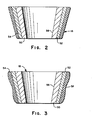
- the grinding roll 18 embodies a trimetat form of construction. More specifically, as best understood with reference to Figures 2 and 3, the grinding roll 18 embodies a main body portion, generally designated by reference numeral 50, that embodies the overall configuration of a roll. In addition to the body portion 50, the grinding roll 18 further embodies two other dissimilar portions of material arranged in layered relation to each other as well as to the body portion 50. To this end, one of these two portions, i.e., that denoted generally by the reference numeral 52 in Figures 2 and 3 of the drawing, is suitably positioned in superimposed relation to the body portion 50 of the grinding roll 18. Similarly, the other of the aforereferenced two portions, i.e., that denoted generally by the reference numeral 54 in Figures 2 and 3 of the drawing, is suitably positioned in superimposed relation to the portion 52.
- the body portion 50 of the grinding roll 18 in accord with the best mode embodiment of the invention is made of a relatively soft, easily machinable material, such as gray iron.
- the body portion 50 has a passage 56 formed entirely therethrough at substantially the center thereof.
- the through passage 56 is suitably dimensioned so as to be capable of receiving therewithin in assembled relation thereto the shaft-like member (not shown) to which reference has previously been made hereinbefore, and on which the grinding roll 18 is suitably supported so as to be capable of functioning in the manner described above and as shown in Figure 1.
- this portion 52 preferably comprises a material that is noted for its medium wear-resistant qualities.
- a material that has been found suitable for use for this purpose is a material referred to by the name Raymix.
- Raymix which has a known composition, can be obtained from the Monongahela plant of applicant's assignee. The reasons why a material having such qualities is selected for use in this context, and the manner in which the portion 52 consisting of Raymix preferably is adhered to the body portion 50 will be found set forth with more particularity hereinafter.
- the last, i.e., portion 54, of the three portions, which collectively comprise the trimetal pulverizer roll 18 preferably consists, in accord with the best mode embodiment of the invention, of a material that is characterized by the fact that it is highly abrasive resistant.
- a material which is suitable for use in this regard, is that known to those skilled in this art as nihard.
- the portion 52 the reasons for employing a material to form the portion 54, i.e., the outer layer of the trimetal pulverizer roll 18 that has the characteristics described above, and the manner in which the portion 54 is affixed to the portion 52 will be found set forth hereinafter with more particularlity.
- At least the outer surface, i.e., that encompassed by the intermediate layer, i.e., portion 52, and the outer layer, i.e., portion 54, to be made of materials that are characterized by their capability to resist wear, and in particular that kind of wear which is occasioned by abrasive action.
- Figure 2 is simply intended to illustrate in a general fashion the nature of the construction in accord with the present invention of the pulverizer, i.e., grinding, roll 18.
- Figure 3 is intended to illustrate a grinding roll 18 constructed in accordance with the present invention wherein therein is depicted in exaggerated fashion the fact that the outer layer, i.e., portion 54, embodies an uneven thickness in contradistinction to the intermediate layer, i.e., portion 52, which is of substantially uniform thickness.
- the external surface of the outer portion 54 i.e., that denoted by the reference numeral 58 in Figure 3 is provided with a specific configuration which is intended to constitute a replication of the wear pattern that a pulverization, i.e., grinding, roll 18 develops as a consequence of its being utilized to effect the pulverization of a material such as coal within a bowl mill 10. That is, the external surface 58 of the outer portion 54 of the grinding roll 18 is suitably configured such that those areas thereof which based on past experience it can be anticipated will be subjected to the greatest degree of wear are made to have a thicker thickness of material, e.g., nihard, thereat.
- the intent in doing so is to attempt to achieve a uniform wear rate of the outer portion 54 by means of providing more material in those areas whereat it is expected that the roll 18 will experrience the most wear based on past experience applied to the use to which the roll 18 is intended to be put.
- the outer portion 54 of the pulverizer, i.e., grinding, roll 18 is intentionally made to have a nonuniform thickness such that more material is provided in those areas whereat more wear is predicted to take place, and less material is provided in those areas whereat less wear is expected to occur.
- the Raymix under the influence of centrifugal force moves outwardly within the mold and forms a layer thereof in abutting engagement to the inner surface of the mold.
- the next step in accord with the subject method is to effect the pouring into the mold of the requisite amount of material, e.g., gray iron, to form the inner, i.e., body, portion 50 of the pulverizer roll 18.
- the gray iron under the influence of centrifugal force forms a layer in abutting engagement with the inner surface of the interme iate portion 52.
- a suitable bonding agent is preferably utilized to cause the outer surface of the inner portion 50 to adhere to the inner surface of the intermediate portion 52.
- the outer portion 54 preferably is applied in the form of a nonuniform thickness of material such that the thicker thickness thereof is located in those areas whereat it is believed, based on the use to which it is known the pulverizer roll 18 will be put, the greatest wear will be experienced.
- the through passage 56 is formed through substantially the center of the body portion 50 during the casting process.
- the pulverizer roll 18 by virtue of its trimetal form of construction embodies a body portion 50 that is capable of being made from a material that is relatively easy to work thereby enabling economies of manufacture to be realized from the use for this purpose of this material, e.g., gray iron.
- the pulverizer roll 18 that embodies a trimetal structure has an external surface that consists of an outer portion 54 which consists of a relatively hard, i.e., highly abrasive resistant material such as nihard that is capable of resisting the abrasive action produced in the course of effecting the pulverization therewith of a material such as coal.
- the pulverizer roll 18 is characterized by the fact that the outer portion 54 wears more slowly, i.e., wears more uniformly. That is, before the outer portion 54 wears through in those areas which are subject to the greatest wear, a more uniform wearing of the entire outer portion 54 is realized.
- the external surface of the pulverizer roll 18 is not composed of simply the outer portion 54. But rather, the external surface further comprises the intermediate portion 52, which also consists of a material having wear-resistant qualities, e.g., Raymix. As a consequence, even when the outer portion 54 is worn through, the pulverizer roll 18 still remains serviceable in that the intermediate portion 52 is also capable of performing the wear-resisting function. It is of course true that the material which comprises the intermediate portion 52 is not as hard, i.e., is not as abrasive resistant as the outer portion 54.
- the pulverizer roll 18 is still capable of being used with the intermediate portion 52 exposed, i.e., serving, as the pulverizing surface.
- the significance of this is that continued usage may be made of the pulverizing roll 18. Namely, no longer is it necessary to immediately replace pulverizer rolls when the outer surface thereof wears through for fear of damaging the roll, i.e., so to preclude the resurfacing of the worn roll.
- the pulverizer roll 18 of the present invention it is possible most frequently, to await the next scheduled shutdown of the bowl mill 10 in order to effect the removal and replacement of the roll 18 after the outer portion 54 thereof has worn through.
- the intermediate portion 52 serves as an adequate surface to effect the continued pulverization therewith of coal within the bowl mill 10. Normally, the life of the intermediate portion 52 before it also wears through is such as to enable a sufficient period of time to expire to reach the next scheduled shutdown of the bowl mill 10.
- Another advantage that derives from the use of dissimilar materials for the intermediate portion 52 and the outer portion 54 is that it is possible to visually recognize when the outer portion 54 has worn through In one or more places. This visual indication is had by noting the different appearance, e.g., color, etc. of each of the two dissimilar materials, i.e., the Raymix of intermediate portion 52 and the nihard of outer portion 54. To further enhance this visual recognition, it is possible to color with a suitable medium, e.g., red paint, the outer surface of the intermediate portion 52 so as to provide the latter with a readily viewable surface before the outer portion 54 is affixed thereto.
- a suitable medium e.g., red paint
- the pulverizer roll 18 constructed in accordance with the present invention provide a roll that has a measurably longer operating life than do the rolls which have heretofore been constructed in accordance with the teachings of the prior art, but also the pulverizer roll 18 is characterized by the fact that even when the outer portion 54 thereof becomes worn through, by virtue of the presence of the intermediate portion 52 continued usage may be made of the pulverizer roll 18 for effecting the pulverization of a material without the roll 18 sustaining damage thereto.
- the pulverizer roll of the present invention is characterized in that it embodies a trimetal mode of construction.
- a trimetal pulverizer roll is provided that is primarily intended to be employed in a bowl mill for purposes of effecting the pulverization therewithin of a material such as coal. Further, the trimetal pulverizer roll of the present invention is distinguishable by its relatively long operating life.
- a trimetal pulverizer roll which has a first portion thereof that is characterized by its ease of machinability, a second portion thereof that is characterized by the fact that it exhibits medium wear-resistant qualities, and a third portion thereof that is characterized by the fact that it exhibits highly abrasive resistant qualities.
- the trimetal pulverizer roll of the present invention while being readily employable in a bowl mill yet also enables significant cost savings to be realized through the use thereof insofar as the operation of the bowl mill is concerned.
- a new and improved method of manufacturing such a trimetal pulverizer roll is provided.
Landscapes
- Engineering & Computer Science (AREA)
- Food Science & Technology (AREA)
- Crushing And Grinding (AREA)
Applications Claiming Priority (2)
| Application Number | Priority Date | Filing Date | Title |
|---|---|---|---|
| US44685082A | 1982-12-06 | 1982-12-06 | |
| US446850 | 1982-12-09 |
Publications (1)
| Publication Number | Publication Date |
|---|---|
| EP0110191A2 true EP0110191A2 (fr) | 1984-06-13 |
Family
ID=23774053
Family Applications (1)
| Application Number | Title | Priority Date | Filing Date |
|---|---|---|---|
| EP83111022A Withdrawn EP0110191A2 (fr) | 1982-12-06 | 1983-11-04 | Rouleau broyeur à trois couches métalliques et procédé de sa fabrication |
Country Status (7)
| Country | Link |
|---|---|
| EP (1) | EP0110191A2 (fr) |
| JP (1) | JPS59109254A (fr) |
| KR (1) | KR840006915A (fr) |
| AU (1) | AU2210183A (fr) |
| CA (1) | CA1212365A (fr) |
| ES (1) | ES8506206A1 (fr) |
| ZA (1) | ZA836139B (fr) |
Cited By (4)
| Publication number | Priority date | Publication date | Assignee | Title |
|---|---|---|---|---|
| EP0234026A3 (fr) * | 1986-02-24 | 1988-05-18 | Combustion Engineering, Inc. | Articles, dont la surface est pourvue d'une couche en matière résistant à l'usure, et leur procédé de fabrication |
| EP0615784A1 (fr) * | 1993-03-16 | 1994-09-21 | THE BABCOCK & WILCOX COMPANY | Galet de brayage |
| CN102544632A (zh) * | 2010-12-07 | 2012-07-04 | 中国电子科技集团公司第十八研究所 | 一种防阻塞锂空气电池 |
| CN112846477A (zh) * | 2020-12-29 | 2021-05-28 | 瓯锟科技温州有限公司 | 一种用于粉末和金属板复合的装置 |
Families Citing this family (2)
| Publication number | Priority date | Publication date | Assignee | Title |
|---|---|---|---|---|
| JPS60209268A (ja) * | 1984-04-03 | 1985-10-21 | 川崎重工業株式会社 | 竪型ミル |
| AU629243B2 (en) * | 1989-09-14 | 1992-10-01 | Kurimoto, Ltd. | Method for manufacturing a crushing roller and method for using the roller |
-
1983
- 1983-06-24 CA CA000431137A patent/CA1212365A/fr not_active Expired
- 1983-08-19 ZA ZA836139A patent/ZA836139B/xx unknown
- 1983-11-04 EP EP83111022A patent/EP0110191A2/fr not_active Withdrawn
- 1983-11-10 KR KR1019830005329A patent/KR840006915A/ko not_active Ceased
- 1983-11-28 ES ES527602A patent/ES8506206A1/es not_active Expired
- 1983-12-05 JP JP58228604A patent/JPS59109254A/ja active Pending
- 1983-12-05 AU AU22101/83A patent/AU2210183A/en not_active Abandoned
Cited By (5)
| Publication number | Priority date | Publication date | Assignee | Title |
|---|---|---|---|---|
| EP0234026A3 (fr) * | 1986-02-24 | 1988-05-18 | Combustion Engineering, Inc. | Articles, dont la surface est pourvue d'une couche en matière résistant à l'usure, et leur procédé de fabrication |
| EP0615784A1 (fr) * | 1993-03-16 | 1994-09-21 | THE BABCOCK & WILCOX COMPANY | Galet de brayage |
| CN102544632A (zh) * | 2010-12-07 | 2012-07-04 | 中国电子科技集团公司第十八研究所 | 一种防阻塞锂空气电池 |
| CN112846477A (zh) * | 2020-12-29 | 2021-05-28 | 瓯锟科技温州有限公司 | 一种用于粉末和金属板复合的装置 |
| CN112846477B (zh) * | 2020-12-29 | 2022-06-28 | 瓯锟科技温州有限公司 | 一种用于粉末和金属板复合的装置 |
Also Published As
| Publication number | Publication date |
|---|---|
| ES527602A0 (es) | 1985-07-01 |
| CA1212365A (fr) | 1986-10-07 |
| ZA836139B (en) | 1984-04-25 |
| ES8506206A1 (es) | 1985-07-01 |
| KR840006915A (ko) | 1984-12-04 |
| AU2210183A (en) | 1984-06-14 |
| JPS59109254A (ja) | 1984-06-23 |
Similar Documents
| Publication | Publication Date | Title |
|---|---|---|
| CA1250156A (fr) | Materiau a haute resistance a l'abrasion | |
| US5516053A (en) | Welded metal hardfacing pattern for cone crusher surfaces | |
| EP0271336B1 (fr) | Eléments broyeurs pour broyeurs | |
| JP2799250B2 (ja) | バイメタル鋳物の製造方法と、この方法で製造される摩耗部品 | |
| US4389767A (en) | Method of manufacturing pulverizer rolls | |
| EP0110191A2 (fr) | Rouleau broyeur à trois couches métalliques et procédé de sa fabrication | |
| US3929296A (en) | Striking tool | |
| US4610401A (en) | Trimetal pulverizer roll | |
| US4610073A (en) | Trimetal pulverizer roll and a method of manufacture thereof | |
| US20070187537A1 (en) | Repairing crusher rolls | |
| CN1005537B (zh) | 具有耐磨表面层的制品 | |
| US6061908A (en) | Energy-efficient grinding rolls for coal pulverizers | |
| US3995782A (en) | Pulverizing device | |
| CA1235105A (fr) | Bague de couronne pour broyeur de charbon | |
| US5538192A (en) | Plunger can and spring compressor | |
| JPH09173883A (ja) | 横型超微粉砕ミル | |
| CN220346071U (zh) | 粉碎或磨碎硬材料的粉碎设备、其转子及转子的耐磨板 | |
| CN207722881U (zh) | 立轴破碎机上冲击下打击转子 | |
| CN214439542U (zh) | 一种磨粉机用耐磨刮刀 | |
| CN218573814U (zh) | 一种加强型中速磨煤机喷嘴环 | |
| US4678131A (en) | Highly abrasive resistant material | |
| JPS58214351A (ja) | 缶の細断装置及び細断方法 | |
| JPS6230820B2 (fr) | ||
| JPS62237956A (ja) | 破砕装置 | |
| JPS61257248A (ja) | ロ−ラミル用ロ−ル |
Legal Events
| Date | Code | Title | Description |
|---|---|---|---|
| PUAI | Public reference made under article 153(3) epc to a published international application that has entered the european phase |
Free format text: ORIGINAL CODE: 0009012 |
|
| AK | Designated contracting states |
Designated state(s): BE DE FR GB IT NL SE |
|
| RAP1 | Party data changed (applicant data changed or rights of an application transferred) |
Owner name: LUMMUS CREST S.A.R.L. |
|
| STAA | Information on the status of an ep patent application or granted ep patent |
Free format text: STATUS: THE APPLICATION HAS BEEN WITHDRAWN |
|
| 18W | Application withdrawn |
Withdrawal date: 19851107 |
|
| RIN1 | Information on inventor provided before grant (corrected) |
Inventor name: MALISZEWSKI, THEODORE VINCENT, JR. |