EP0110231A2 - Appareil pour focaliser et mélanger un faisceau laser - Google Patents
Appareil pour focaliser et mélanger un faisceau laser Download PDFInfo
- Publication number
- EP0110231A2 EP0110231A2 EP83111387A EP83111387A EP0110231A2 EP 0110231 A2 EP0110231 A2 EP 0110231A2 EP 83111387 A EP83111387 A EP 83111387A EP 83111387 A EP83111387 A EP 83111387A EP 0110231 A2 EP0110231 A2 EP 0110231A2
- Authority
- EP
- European Patent Office
- Prior art keywords
- fact
- mirrors
- focusing
- laser beam
- mirror
- Prior art date
- Legal status (The legal status is an assumption and is not a legal conclusion. Google has not performed a legal analysis and makes no representation as to the accuracy of the status listed.)
- Withdrawn
Links
Images
Classifications
-
- B—PERFORMING OPERATIONS; TRANSPORTING
- B23—MACHINE TOOLS; METAL-WORKING NOT OTHERWISE PROVIDED FOR
- B23K—SOLDERING OR UNSOLDERING; WELDING; CLADDING OR PLATING BY SOLDERING OR WELDING; CUTTING BY APPLYING HEAT LOCALLY, e.g. FLAME CUTTING; WORKING BY LASER BEAM
- B23K26/00—Working by laser beam, e.g. welding, cutting or boring
- B23K26/08—Devices involving relative movement between laser beam and workpiece
-
- B—PERFORMING OPERATIONS; TRANSPORTING
- B23—MACHINE TOOLS; METAL-WORKING NOT OTHERWISE PROVIDED FOR
- B23K—SOLDERING OR UNSOLDERING; WELDING; CLADDING OR PLATING BY SOLDERING OR WELDING; CUTTING BY APPLYING HEAT LOCALLY, e.g. FLAME CUTTING; WORKING BY LASER BEAM
- B23K26/00—Working by laser beam, e.g. welding, cutting or boring
- B23K26/02—Positioning or observing the workpiece, e.g. with respect to the point of impact; Aligning, aiming or focusing the laser beam
-
- B—PERFORMING OPERATIONS; TRANSPORTING
- B23—MACHINE TOOLS; METAL-WORKING NOT OTHERWISE PROVIDED FOR
- B23K—SOLDERING OR UNSOLDERING; WELDING; CLADDING OR PLATING BY SOLDERING OR WELDING; CUTTING BY APPLYING HEAT LOCALLY, e.g. FLAME CUTTING; WORKING BY LASER BEAM
- B23K26/00—Working by laser beam, e.g. welding, cutting or boring
- B23K26/08—Devices involving relative movement between laser beam and workpiece
- B23K26/082—Scanning systems, i.e. devices involving movement of the laser beam relative to the laser head
-
- G—PHYSICS
- G02—OPTICS
- G02B—OPTICAL ELEMENTS, SYSTEMS OR APPARATUS
- G02B19/00—Condensers, e.g. light collectors or similar non-imaging optics
- G02B19/0004—Condensers, e.g. light collectors or similar non-imaging optics characterised by the optical means employed
- G02B19/0019—Condensers, e.g. light collectors or similar non-imaging optics characterised by the optical means employed having reflective surfaces only (e.g. louvre systems, systems with multiple planar reflectors)
- G02B19/0023—Condensers, e.g. light collectors or similar non-imaging optics characterised by the optical means employed having reflective surfaces only (e.g. louvre systems, systems with multiple planar reflectors) at least one surface having optical power
-
- G—PHYSICS
- G02—OPTICS
- G02B—OPTICAL ELEMENTS, SYSTEMS OR APPARATUS
- G02B19/00—Condensers, e.g. light collectors or similar non-imaging optics
- G02B19/0033—Condensers, e.g. light collectors or similar non-imaging optics characterised by the use
-
- G—PHYSICS
- G02—OPTICS
- G02B—OPTICAL ELEMENTS, SYSTEMS OR APPARATUS
- G02B7/00—Mountings, adjusting means, or light-tight connections, for optical elements
- G02B7/18—Mountings, adjusting means, or light-tight connections, for optical elements for prisms; for mirrors
- G02B7/182—Mountings, adjusting means, or light-tight connections, for optical elements for prisms; for mirrors for mirrors
- G02B7/1822—Mountings, adjusting means, or light-tight connections, for optical elements for prisms; for mirrors for mirrors comprising means for aligning the optical axis
- G02B7/1827—Motorised alignment
Definitions
- the present invention relates to a device for focusing and blending a power laser beam.
- the light spot on the focusing surface must not only conform with preset dimensions but also present an energy distribution pattern as uniform as possible.
- heat treating applications have required the design of new optical arrangements, known as dynamic systems, for blending the energy of the beam on the focusing surface.
- blending is essentially intended to mean distributing the energy of the laser beam as evenly as possible over its cross section.
- a known method of doing this consists in turning the laser beam round its own propagation axis by setting rotary mirrors up asymmetrically along the beam propagation path.
- the aim of the present invention is to provide a device for focusing and blending a laser beam, so as to overcome the drawbacks presented by the abovementioned known types.
- the present invention relates to a device for focusing and blending a laser beam, characterised by the fact that it comprises :
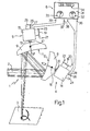
- Number in Fig.1 indicates a device for focusing and blending a laser beam ( 2 ) on a focusing surface (3).
- Device 1 essentially comprises two units (4, 5), for optical processing of beam 2 , and a processing and display unit (6), connected to the said units 4 and 5.
- the latter are identical and each comprise a round mirror (8, 9), with a spherical,. concave relfecting surface ( 1 0, 11 ), connected to the end of a shaft (1 2 , 13 ) on an electric motor (1 4 , 15 ) by means of an adjustable coupling ( 1 6, 1 7).
- the latter provides for adjusting the angle (a, B ) of each mirror (8, 9) in relation to the axis of the corresponding shaft (12, 13).
- the speed of shaft 12, 13 on motor 14, 15 is regulated by means of a speed variator consisting of a rheostat ( 1 8, 1 9) with its supply terminals (20, 2 2 and 21 , 23 ) connected to the negative and positive poles respectively of a d.c. supply source (not shown).
- a speed variator consisting of a rheostat ( 1 8, 1 9) with its supply terminals (20, 2 2 and 21 , 23 ) connected to the negative and positive poles respectively of a d.c. supply source (not shown).
- Each motor (14, 15 ) is assigned a speedometer dynamo (24, 25) the voltage at the terminals of which is proportional to the speed of the shaft on the respective motor.
- Each dynamo ( 24 , 25 ) is fitted with output terminals ( 2 6, 28 and 27, 29 ) each of which is connected to a respective terminal (36, 38 and 37, 39) on processing unit 6.
- the latter has a panel (31) fitted with two analogue indicators (3 2 , 33) showing the rotation speed of the shaft on each motor (14, 15).
- Panel 31 is also fitted with a 7-section logic display (34) showing the ratio between the shaft rotation speeds on motors 14 and 15.
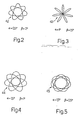
- Fig.s 2 to 5 show patterns (42, 43, 44, 45) drawn by the end of beam 2 on work surface 3, depending on the said angles a and B.
- angles a and R are set by means of couplings 16 and 1 7.
- the size of the angle determines the size and, in part, the shape of the patterns described on the focusing surface by beam 2 (see Fig.s 2, 3, 4 and 5).
- the speed of shafts 12 and 13 on motors 14 and 15 is than set using the slides on rheostats 1 8 and 19 , at the same time checking the indicators (32, 33 and 34) on unit 6.
- the speed the said shafts are set to determines the speed at which each pattern is drawn on the focusing surface, whereas the ratio between the said speeds determines the number of "petals" on each pattern. In our case, the said ratio is 0.75 for each of figures 2 to 5 which, as can be seen all have the same number of metals (7).
- Laser beam 2 which is horizontal in Fig. l , is intercep ted by surface 1 0 on concave mirror 8 which provides for initial focusing and directing the beam towards surface 1 1 on concave mirror 9. On leaving the latter, laser beam 2 is further focuses and aimed finally towards the preset working area on surface 3.
- Energy distribution on beam 2 is essentially uniform and covering a fairly wide area.
- the pattern described by beam 2 on surface 3 is determined by the combined motion produced by the rotation of mirrors 8 and 9, the actual design of the pattern being one of an essentially countless number produced by combining the various parameters on device 1.
- Device 1 provides.for easy, simultaneous focusing and blending of any type of laser beam with no need for the said focusing systems up- and downstream. What is more, device 1 is extremely cheap to prolude on account of the fact that units 4 and 5 are not only identical but also simple in design.
- two separate motors are used for turning mirrors 8 and 9 makes device 1 extremely versatile, in that each of the patterns described by laser beam 2 on working surface 3 may be completed over widely differing lengths of time.
- any fluctuation in the speed of motors 14 and 15 merely determines an open pattern, instead of a closed one as shown in Fig.s 2 to 5, which only serves to improve the blending function of device 1 further.
- changes can be made to the device ( 1 ) described by way of a non-limiting example, without, however, departing
- either of units 4, 5 could be limited sole ly to the concave mirror and regulating coupling and, vice versa, the drive of the other unit motor using a suitable drive chain.
Landscapes
- Physics & Mathematics (AREA)
- Optics & Photonics (AREA)
- Engineering & Computer Science (AREA)
- Plasma & Fusion (AREA)
- Mechanical Engineering (AREA)
- General Physics & Mathematics (AREA)
- Laser Beam Processing (AREA)
- Mechanical Optical Scanning Systems (AREA)
- Lenses (AREA)
- Lasers (AREA)
Applications Claiming Priority (2)
| Application Number | Priority Date | Filing Date | Title |
|---|---|---|---|
| IT68386/82A IT1157960B (it) | 1982-11-29 | 1982-11-29 | Dispositivo per focalizzare ed omogeneizzare un fascio laser |
| IT6838682 | 1982-11-29 |
Publications (2)
| Publication Number | Publication Date |
|---|---|
| EP0110231A2 true EP0110231A2 (fr) | 1984-06-13 |
| EP0110231A3 EP0110231A3 (fr) | 1985-08-07 |
Family
ID=11309223
Family Applications (1)
| Application Number | Title | Priority Date | Filing Date |
|---|---|---|---|
| EP83111387A Withdrawn EP0110231A3 (fr) | 1982-11-29 | 1983-11-14 | Appareil pour focaliser et mélanger un faisceau laser |
Country Status (3)
| Country | Link |
|---|---|
| EP (1) | EP0110231A3 (fr) |
| JP (1) | JPS59111618A (fr) |
| IT (1) | IT1157960B (fr) |
Cited By (7)
| Publication number | Priority date | Publication date | Assignee | Title |
|---|---|---|---|---|
| WO1987005843A1 (fr) * | 1986-03-26 | 1987-10-08 | Nauchno-Issledovatelsky Tsentr Po Tekhnologicheski | Installation pour le traitement des materiaux a l'aide d'un laser |
| EP0349347A1 (fr) * | 1988-06-30 | 1990-01-03 | Kabushiki Kaisha Toshiba | Système de marquage optique avec une fonction de sélection pour la forme de marquage |
| US5198843A (en) * | 1988-06-30 | 1993-03-30 | Kabushiki Kaisha Toshiba | Optical marking system having marking mode selecting function |
| US5245563A (en) * | 1991-09-20 | 1993-09-14 | Kendall Square Research Corporation | Fast control for round unit |
| EP0732168A3 (fr) * | 1995-03-15 | 1997-04-09 | Sumitomo Electric Industries | Méthode et appareil pour la focalisation d'un faisceau laser |
| GB2329724A (en) * | 1997-09-24 | 1999-03-31 | Samsung Electronics Co Ltd | A view selecting apparatus for an X-ray inspection system |
| DE102014012456A1 (de) * | 2014-08-21 | 2016-02-25 | Steinmeyer Mechatronik GmbH | Optische Strahlführungseinheit und Materialbearbeitungsvorrichtung mit einer optischen Strahlführungseinheit |
Family Cites Families (4)
| Publication number | Priority date | Publication date | Assignee | Title |
|---|---|---|---|---|
| NL7103141A (fr) * | 1970-03-11 | 1971-09-14 | ||
| US4049945A (en) * | 1973-10-10 | 1977-09-20 | Winkler & Dunnebier Maschinenfabrik Und Eisengiesserei Kg | Method of and apparatus for cutting material to shape from a moving web by burning |
| GB1507204A (en) * | 1974-07-12 | 1978-04-12 | Caterpillar Tractor Co | Apparatus for heat treating an internal bore in a workpiece |
| JPS5919798B2 (ja) * | 1974-11-01 | 1984-05-08 | 株式会社日立製作所 | レ−ザ加工装置 |
-
1982
- 1982-11-29 IT IT68386/82A patent/IT1157960B/it active
-
1983
- 1983-11-14 EP EP83111387A patent/EP0110231A3/fr not_active Withdrawn
- 1983-11-28 JP JP58225324A patent/JPS59111618A/ja active Pending
Cited By (9)
| Publication number | Priority date | Publication date | Assignee | Title |
|---|---|---|---|---|
| WO1987005843A1 (fr) * | 1986-03-26 | 1987-10-08 | Nauchno-Issledovatelsky Tsentr Po Tekhnologicheski | Installation pour le traitement des materiaux a l'aide d'un laser |
| US4797532A (en) * | 1986-03-26 | 1989-01-10 | Maiorov Vladimir S | Apparatus for laser treatment of materials |
| EP0349347A1 (fr) * | 1988-06-30 | 1990-01-03 | Kabushiki Kaisha Toshiba | Système de marquage optique avec une fonction de sélection pour la forme de marquage |
| US5198843A (en) * | 1988-06-30 | 1993-03-30 | Kabushiki Kaisha Toshiba | Optical marking system having marking mode selecting function |
| US5245563A (en) * | 1991-09-20 | 1993-09-14 | Kendall Square Research Corporation | Fast control for round unit |
| EP0732168A3 (fr) * | 1995-03-15 | 1997-04-09 | Sumitomo Electric Industries | Méthode et appareil pour la focalisation d'un faisceau laser |
| US5889626A (en) * | 1995-03-15 | 1999-03-30 | Sumitomo Electric Industries, Ltd. | Method and device for focusing laser beam |
| GB2329724A (en) * | 1997-09-24 | 1999-03-31 | Samsung Electronics Co Ltd | A view selecting apparatus for an X-ray inspection system |
| DE102014012456A1 (de) * | 2014-08-21 | 2016-02-25 | Steinmeyer Mechatronik GmbH | Optische Strahlführungseinheit und Materialbearbeitungsvorrichtung mit einer optischen Strahlführungseinheit |
Also Published As
| Publication number | Publication date |
|---|---|
| IT1157960B (it) | 1987-02-18 |
| JPS59111618A (ja) | 1984-06-27 |
| IT8268386A1 (it) | 1984-05-29 |
| IT8268386A0 (it) | 1982-11-29 |
| EP0110231A3 (fr) | 1985-08-07 |
Similar Documents
| Publication | Publication Date | Title |
|---|---|---|
| US10444521B2 (en) | Device for machining material by means of laser radiation | |
| US4701591A (en) | Apparatus for processing multiple workpieces utilizing a single laser beam source | |
| US4822974A (en) | Laser hold drilling system with lens and two wedge prisms including axial displacement of at least one prism | |
| US4675501A (en) | Laser apparatus with novel beam aligning means and method of laser processing of workpieces using same | |
| US5587094A (en) | Laser marking apparatus | |
| JPH0380596B2 (fr) | ||
| GB2199158A (en) | Light beam switching system for optical fibres | |
| US3993402A (en) | Apparatus for directing a laser beam | |
| US4499362A (en) | Rotary beam chopper with continuously variable duty cycle | |
| US4491383A (en) | Device for modifying and uniforming the distribution of the intensity of a power laser beam | |
| CA2201365A1 (fr) | Dispositif de balayage a laser | |
| CN110133842A (zh) | 一种振镜扫描装置及系统 | |
| US5365032A (en) | Method of cutting by means of laser radiation | |
| CN210677356U (zh) | 一种可调多功能手持式激光焊接枪 | |
| JPS59111618A (ja) | レ−ザ・ビ−ムの集束および混合装置 | |
| GB2120804A (en) | Deflection device for laser beam in thermal surface treatments of splined pieces | |
| US4363539A (en) | Photohead with flashing beam | |
| EP0022825B1 (fr) | Methode de traitement d'une piece sur laquelle un faisceau de radiation est dirige | |
| JPS59107785A (ja) | レ−ザ加工用多関節ア−ム型ロボツト | |
| JPS5647288A (en) | Laser working apparatus | |
| JPH058072A (ja) | レーザ加工方法 | |
| CN209911649U (zh) | 一种振镜扫描装置及系统 | |
| CN221361662U (zh) | 一种自动聚焦的可环绕式激光清洗装置 | |
| JPH04200886A (ja) | レーザマーキング装置 | |
| JPH03174995A (ja) | レーザ加工装置の加工ヘッド |
Legal Events
| Date | Code | Title | Description |
|---|---|---|---|
| PUAI | Public reference made under article 153(3) epc to a published international application that has entered the european phase |
Free format text: ORIGINAL CODE: 0009012 |
|
| AK | Designated contracting states |
Designated state(s): AT BE CH DE FR GB LI NL SE |
|
| PUAL | Search report despatched |
Free format text: ORIGINAL CODE: 0009013 |
|
| AK | Designated contracting states |
Designated state(s): AT BE CH DE FR GB LI NL SE |
|
| STAA | Information on the status of an ep patent application or granted ep patent |
Free format text: STATUS: THE APPLICATION HAS BEEN WITHDRAWN |
|
| 18W | Application withdrawn |
Withdrawal date: 19851121 |
|
| RIN1 | Information on inventor provided before grant (corrected) |
Inventor name: FERRARI, GIANCARLO Inventor name: PERA, LUCIANO |