EP0110321A2 - Débitmètre à vortex - Google Patents
Débitmètre à vortex Download PDFInfo
- Publication number
- EP0110321A2 EP0110321A2 EP83111731A EP83111731A EP0110321A2 EP 0110321 A2 EP0110321 A2 EP 0110321A2 EP 83111731 A EP83111731 A EP 83111731A EP 83111731 A EP83111731 A EP 83111731A EP 0110321 A2 EP0110321 A2 EP 0110321A2
- Authority
- EP
- European Patent Office
- Prior art keywords
- flow meter
- pressure
- vortex flow
- conduit
- fluid
- Prior art date
- Legal status (The legal status is an assumption and is not a legal conclusion. Google has not performed a legal analysis and makes no representation as to the accuracy of the status listed.)
- Granted
Links
- 239000012530 fluid Substances 0.000 claims abstract description 32
- 230000006698 induction Effects 0.000 claims abstract description 14
- 230000004044 response Effects 0.000 claims abstract description 6
- 239000000758 substrate Substances 0.000 claims description 10
- 238000010894 electron beam technology Methods 0.000 claims description 6
- 239000000945 filler Substances 0.000 claims description 5
- 238000003466 welding Methods 0.000 claims description 3
- 229910010293 ceramic material Inorganic materials 0.000 claims description 2
- 239000004020 conductor Substances 0.000 claims description 2
- 239000011521 glass Substances 0.000 claims description 2
- 238000006073 displacement reaction Methods 0.000 abstract description 8
- 238000010276 construction Methods 0.000 description 7
- 230000004048 modification Effects 0.000 description 5
- 238000012986 modification Methods 0.000 description 5
- 230000035945 sensitivity Effects 0.000 description 3
- 238000005259 measurement Methods 0.000 description 2
- 241001640034 Heteropterys Species 0.000 description 1
- 230000006872 improvement Effects 0.000 description 1
- 239000007788 liquid Substances 0.000 description 1
- 238000003754 machining Methods 0.000 description 1
- 238000004519 manufacturing process Methods 0.000 description 1
- 239000012528 membrane Substances 0.000 description 1
- 238000000034 method Methods 0.000 description 1
- 239000003595 mist Substances 0.000 description 1
- 238000000465 moulding Methods 0.000 description 1
- 230000010355 oscillation Effects 0.000 description 1
Images



Classifications
-
- G—PHYSICS
- G01—MEASURING; TESTING
- G01F—MEASURING VOLUME, VOLUME FLOW, MASS FLOW OR LIQUID LEVEL; METERING BY VOLUME
- G01F1/00—Measuring the volume flow or mass flow of fluid or fluent solid material wherein the fluid passes through a meter in a continuous flow
- G01F1/05—Measuring the volume flow or mass flow of fluid or fluent solid material wherein the fluid passes through a meter in a continuous flow by using mechanical effects
- G01F1/20—Measuring the volume flow or mass flow of fluid or fluent solid material wherein the fluid passes through a meter in a continuous flow by using mechanical effects by detection of dynamic effects of the flow
- G01F1/32—Measuring the volume flow or mass flow of fluid or fluent solid material wherein the fluid passes through a meter in a continuous flow by using mechanical effects by detection of dynamic effects of the flow using swirl flowmeters
- G01F1/325—Means for detecting quantities used as proxy variables for swirl
- G01F1/3259—Means for detecting quantities used as proxy variables for swirl for detecting fluid pressure oscillations
- G01F1/3266—Means for detecting quantities used as proxy variables for swirl for detecting fluid pressure oscillations by sensing mechanical vibrations
-
- Y—GENERAL TAGGING OF NEW TECHNOLOGICAL DEVELOPMENTS; GENERAL TAGGING OF CROSS-SECTIONAL TECHNOLOGIES SPANNING OVER SEVERAL SECTIONS OF THE IPC; TECHNICAL SUBJECTS COVERED BY FORMER USPC CROSS-REFERENCE ART COLLECTIONS [XRACs] AND DIGESTS
- Y10—TECHNICAL SUBJECTS COVERED BY FORMER USPC
- Y10S—TECHNICAL SUBJECTS COVERED BY FORMER USPC CROSS-REFERENCE ART COLLECTIONS [XRACs] AND DIGESTS
- Y10S73/00—Measuring and testing
- Y10S73/04—Piezoelectric
Definitions
- a flange for mounting the pressure sensor on the outer wall of the conduit and a cylindrical member for accommodating the sensor member are formed independently of each other and then welded together by an electron beam or the like.
- a support wall for fixing the cylindrical member extends from the flange.
- a second sensor member identical in construction with the first is employed to compensate for externally derived vibrations which may act on the pressure sensor. Leads extending out from the pressure sensor have a small rigidity.
- the present invention relates to an improved vortex flow meter for measuring the velocity and flow rate of a fluid flowing through a conduit by sensing a delicate pressure variation caused by a vortex train, which a buffle body disposed in the conduit sheds on the movement of the fluid past the buffle body, and converting the sensed pressure variation into an electric signal by means of a piezoelectric element or the like.
- Vortex flow meters of the type described is disclosed in Japanese Utility Model Publication No. 46-21501/1971.
- This prior art vortex flow meter includes a strain gauge or like displacement sensor mounted on a membrane such as a diaphragm, so that a displacement sensed by the sensor is transformed into an electric signal.
- a flow meter construction suffers from various drawbacks as enumerated below due to the inherent location of the sensor inside a narrow space formed in a bluff body.
- a vortex flow meter for measuring a flow rate of a fluid flowing through an internal space of a conduit by sensing a pressure variation which occurs in proportion to the flow rate of the present invention comprises a bluff body disposed in the internal space of the conduit to face the flow of the fluid and having a pressure sensing chamber defined in an internal space thereof, the pressure sensing chamber having an upper pressure induction passageway and a lower pressure induction passageway, a pressure receiving member disposed in the internal space of the bluff body to be displaceable in response to the pressure variation, a sensor member arranged to be positioned in a wall portion of the conduit and outwardly thereof, and a cylindrical member mounted in the wall portion of the conduit and connected to the pressure receiving member at a lower end thereof, the cylindrical member accommodating the sensor member fixed in place in an internal space thereof.
- a vortex flow meter includes a bluff body which sheds a vortex train when a fluid flowing in a conduit moves therepast, the vortex train developing a delicate pressure variation in proportion to a flow rate of the fluid.
- the flow meter detects the flow rate by sensing the pressure variation and then converting it into an electric signal by means of a piezoelectric element or the like.
- a pressure sensor is detachably mounted in a pressure sensing chamber, which is defined in an internal space of the bluff body, and comprises a pressure receiving plate displaceable in response to the pressure variation, a sensor member such as a piezoelectric element for converting the displacement into an electric signal.
- the pressure receiving plate is arranged such that major part thereof is located in the conduit, while major part of the sensor member is located in a wall of the conduit and the outside thereof.
- the side surfaces of the pressure receiving plate are oriented parallel to or perpendicular to a direction of flow of the fluid.
- a drain port is located below a pressure induction port which is formed in a bottom portion of the pressure sensing chamber, so that part of the fluid entering the pressure sensing chamber is discharged through the drain port.
- the bottom wall of the pressure sensing chamber is inclined radially outwardly or formed with an upright wall.
- a flange for mounting the pressure sensor on the outer wall of the conduit and a cylindrical member for accommodating the sensor member are formed independently of each other and then welded together by an electron beam or the like.
- a support wall for fixing the cylindrical member extends from the flange.
- a second sensor member identical in construction with the first is employed to compensate for an externally derived vibrations which may act on the pressure sensor. Leads extending out from the pressure sensor have a small
- vortex flow meter of the present invention is susceptible of numerous physical embodiments, depending upon the environment and requirements of use, substantial numbers of the herein shown and described embodiments have been made, tested and used, and all have performed in an eminently satisfactory manner.
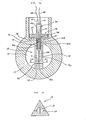
- a vortex flow meter embodying the present invention is shown as being disposed in a conduit 10.
- the conduit 10 has a space 12 defined therein for the passage of liquid, gas or like fluid whose flow rate is to be measured.
- An opening 14 extends throughout the conduit 10 to communicate the space 12 to the outside.
- the outer wall of the conduit 10 is machined in a portion thereof where the opening 14 is located, the machined portion defining a flat surface 16 as illustrated.
- the vortex flow meter includes a bluff body or vortex shedder generally designated by the reference numeral 18.
- the bluff body 18 is disposed in the space 12 of the conduit 10 to face the flow of the fluid and may have a triangular cross-section as illustrated in Figure lb by way of example.
- a central portion of the bluff body 18 is bored to have a relatively wide space which is substantially common in inside diameter to the through opening 14 in the conduit 10 and intercommunicated to the opening 14.
- This space in the bluff body 18 is adapted to sense pressure variations due to a vortex train as will be described.
- Pressure induction passageways 22 and 24 extend throughout the bluff body 18 in upper and lower portions of the space or pressure sensing chamber 20 respectively. As shown in Figure lb, each of the pressure induction passageways 22 and 24 is located to oppose both sides of a flat pressure receiving plate 36, which will be described.
- a pressure sensor, generally 26, is detachably mounted in the intercommunicated opening 14 and pressure sensing chamber 20 in order to convert a pressure variation due to a vortex train into an electric signal.
- the pressure sensor 26 comprises a flange 28 rigidly connected to the flat surface 16 of the conduit 10 by suitable connecting means, a relatively thin-walled hollow cylindrical member 30 which is substantially bisected by the flange 28 into an upper portion 30a and a lower portion 30b intercommunicated with the upper cylinder 30a, and a sensor member 34 rigidly mounted in the bore of the hollow cylindrical member 30 by means of an electrically insulative filling agent 32.
- the flat pressure receiving plate 36 extends downwardly from one end of the cylindrical member 30, i.e., lower end of the lower cylindrical portion 30b, to protrude into the pressure sensing chamber 20 in the bluff body 18 in such a manner as to bisect it.
- the sensor member 34 is made up of a resilient substrate 38 extending substantially along the axis of the cylinder 30, and a pair of piezoelectric elements 40a and 40b which are bonded to opposite surfaces of the substrate 38. These structural elements of the sensor 34 are fixed in place together by the filling agent 32 inside the cylinder 30.
- the substrate 38 and the piezoelectric elements 40a and 40b are electrically connected to terminals 42 and 44 on the upper cylinder portion 30a respectively. Leads 46 and 48 respectively extend from the termianls 42 and 44 to an electric measuring circuit (not shown).
- the piezoelectric elements 40a and 40b bonded to the surfaces of the substrate 38 are covered with a ceramic material and then fixed in place by glass or like filling agent.
- the bluff body 18 sheds a vortex train at both sides thereof in a well known manner in accordance with a velocity of the fluid.
- the vortex train is introduced as a pressure variation into the pressure sensing chamber 20 via the upper and lower pressure induction passageways 22 and 24, thereby developing a delicate fluctuation in the pressure inside the chamber 20.
- the pressure receiving plate 36 associated with the cylinder 30 oscillates as indicated by an arrow A in Figure la and this oscillation is imparted to the substrate 38 and piezoelectric elements 40a and 40b.
- Such a displacement is transformed by the piezoelectric elements 40a and 40b into an electric signal which is then applied via the leads 46 and 48 to the electric measuring circuit.
- the instantaneous flow velocity and flow rate of the fluid in the conduit 10 are determined.
- opposite surfaces of the plate 36 in the chamber 20 are so oriented as to be parallel to the direction of the fluid flow in the conduit 10 as shown in Figure la, while the pressure induction passageways 22 and 24 are positioned to individually face both sides of the plate 36 in the chamber 20 as shown in Figure lb.
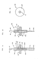
- This is not restrictive, however, and may be replaced by an arrangement shown in Figures 2a-2e in which both sides of the plate 36 extend perpendicularly to the direction of fluid flow while, as shown in Figure 2b, the pressure induction passageways 22 and 24 individually open into the chamber 20 in such a manner as to face both surfaces of the plate 36.
- the alternative arrangement shown in Figures 2a-2e is successful to suppress the influence of mechanical vibrations of the conduitwork on the accuracy of measurement.
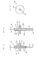
- the bluff body 18 is formed with drain ports 52 at a level lower than the lower pressure induction passageway 24 and even lower than the lower end 36a of the pressure receiving plate 36.
- drain ports 52 at a level lower than the lower pressure induction passageway 24 and even lower than the lower end 36a of the pressure receiving plate 36.
- a wall 54 facing the lower end 36a of the plate 36 may be formed upright in a central area of the chamber bottom 20a, as illustrated in Figure 3a.
- the wall 54 defines the clearance 50 at a level higher than the drain ports 52.
- Figure 3b Another possible implementation for effective discharge of the fluid is shown in Figure 3b in which the chamber bottom 20a is inclined downwardly toward the drain ports 52.
- the flange 28 and the thin cylinder 30 of the pressure sensor 26 have been shown and described as being in an integral structrue, they may be formed as separate members as shown in Figures 4a and 4b.
- the flange 28 has a through bore 56 the inside diameter of which is somewhat larger than the outside diameter of the cylinder 30.
- Annular support walls 58a and 58b extend away from each other from opposite ends of the flange 28, while defining extensions of the through bore 56 thereinside. When the cylinder 30 is coupled in the through bore 56 of the flange 28, the support walls 58a and 58b extend along the axis of the cylinder 30.
- the cylinder 30 After the cylinder 30 is suitably positioned relative to the flange 28, they are welded together by the application of an electron beam, a laser or the like from the outside. Welding with an electron beam, a laser or like means realizes accurate machining eliminating various drawbacks experienced with conventional welding techniques such as thermal distortion due to the large heat capacity.
- provision of the two flanges 58a and 58b is not essential and either one of them may be omitted depending upon the operating conditions as well as others.
- the plate 36 and cylinder 30 may be formed separately from each other and joined together using an electron beam or a laser, instead of forming them integrally as in the first embodiment.
- the vortex flow meter includes a second sensor member 60 in addition to the sensor member 34 of the first embodiment.
- the sensor members 34 and 60 are substantially identical in construction and positioned substantially symmetrically to each other withe respect to the flange 28.
- the sensor member 60 shares the resilient substrate 38 with the sensor member 34 and has piezoelectric elements 62a and 62b individually bonded to oppoiste surfaces thereof.
- a lead support tube 64 having a relatively thin wall is rigidly mounted at one end 64a thereof on the flange 28 of the pressure sensor while surrounding the entire cylinder 30.
- the other end 64b of the lead support tube 64 is hermetically closed by a seal member 66.
- the leads 46 and 48 extending from the pressure sensor 26 via the terminals 42 and 44 are individually made of a conductor having a relatively small rigidity.
- the leads 46 and 48 are respectively connected to terminals 70 and 72 which are fixed to the seal member 66 by a molding 68.
- the terminals 70 and 72 are individually connected to an electric measuring circuit 74.
- the lead support tube 64 may comprise a bellows.
Landscapes
- Physics & Mathematics (AREA)
- Fluid Mechanics (AREA)
- General Physics & Mathematics (AREA)
- Measuring Volume Flow (AREA)
Applications Claiming Priority (12)
| Application Number | Priority Date | Filing Date | Title |
|---|---|---|---|
| JP57206800A JPS5997007A (ja) | 1982-11-25 | 1982-11-25 | 渦流量計 |
| JP57206801A JPS5997008A (ja) | 1982-11-25 | 1982-11-25 | 渦流量計 |
| JP206800/82 | 1982-11-25 | ||
| JP206801/82 | 1982-11-25 | ||
| JP116935/83U | 1983-07-26 | ||
| JP116936/83U | 1983-07-26 | ||
| JP116937/83U | 1983-07-26 | ||
| JP11693583U JPS6023742U (ja) | 1983-07-26 | 1983-07-26 | 微小変動圧力検出器 |
| JP11693683U JPS6023721U (ja) | 1983-07-26 | 1983-07-26 | 渦流量計渦検出装置 |
| JP11693783U JPS6023722U (ja) | 1983-07-26 | 1983-07-26 | 渦流量計 |
| JP14688883U JPS6054942U (ja) | 1983-09-22 | 1983-09-22 | 微小変動圧力検出器 |
| JP146888/83U | 1983-09-22 |
Publications (3)
| Publication Number | Publication Date |
|---|---|
| EP0110321A2 true EP0110321A2 (fr) | 1984-06-13 |
| EP0110321A3 EP0110321A3 (en) | 1984-12-12 |
| EP0110321B1 EP0110321B1 (fr) | 1988-09-07 |
Family
ID=27552487
Family Applications (1)
| Application Number | Title | Priority Date | Filing Date |
|---|---|---|---|
| EP83111731A Expired EP0110321B1 (fr) | 1982-11-25 | 1983-11-23 | Débitmètre à vortex |
Country Status (4)
| Country | Link |
|---|---|
| US (1) | US4627295A (fr) |
| EP (1) | EP0110321B1 (fr) |
| CA (1) | CA1206351A (fr) |
| DE (1) | DE3377936D1 (fr) |
Cited By (2)
| Publication number | Priority date | Publication date | Assignee | Title |
|---|---|---|---|---|
| DE4122799A1 (de) * | 1991-07-10 | 1993-01-21 | Iwk Regler Kompensatoren | Vorrichtung zum messen der geschwindigkeit eines fluids |
| EP0758077A1 (fr) * | 1995-08-07 | 1997-02-12 | Oval Corporation | Détecteur pour un débitmètre à induction de vortex et débitmètre à induction de vortex |
Families Citing this family (16)
| Publication number | Priority date | Publication date | Assignee | Title |
|---|---|---|---|---|
| US4625564A (en) * | 1983-12-02 | 1986-12-02 | Oval Engineering Co., Ltd. | Vortex flow meter |
| DE3544198A1 (de) * | 1985-12-13 | 1987-06-19 | Flowtec Ag | Wirbelstroemungsmesser |
| US4735094A (en) * | 1987-01-28 | 1988-04-05 | Universal Vortex, Inc. | Dual bluff body vortex flowmeter |
| USD335096S (en) | 1987-01-28 | 1993-04-27 | David Marsh | Bluff body flowmeter |
| US4706503A (en) * | 1987-01-30 | 1987-11-17 | Itt Corporation | Vortex meter sensor |
| US4791818A (en) * | 1987-07-20 | 1988-12-20 | Itt Corporation | Cantilever beam, insertable, vortex meter sensor |
| US4926695A (en) * | 1987-09-15 | 1990-05-22 | Rosemount Inc. | Rocking beam vortex sensor |
| CH687420A5 (de) * | 1993-11-22 | 1996-11-29 | Fischer Georg Rohrleitung | Einrichtung zur Messung der Geschwindigkeit eines Fluides. |
| DE4441129A1 (de) * | 1994-11-21 | 1996-05-23 | Junkalor Gmbh | Meßwertgeber für einen Wirbeldurchflußmesser |
| US6220103B1 (en) * | 1996-07-15 | 2001-04-24 | Engineering Measurements Company | Vortex detector and flow meter |
| JPH10142017A (ja) * | 1996-11-11 | 1998-05-29 | Saginomiya Seisakusho Inc | カルマン渦流量計 |
| US5869772A (en) * | 1996-11-27 | 1999-02-09 | Storer; William James A. | Vortex flowmeter including cantilevered vortex and vibration sensing beams |
| US5804740A (en) * | 1997-01-17 | 1998-09-08 | The Foxboro Company | Capacitive vortex mass flow sensor |
| DE102012015887B4 (de) * | 2012-08-13 | 2014-10-02 | Krohne Messtechnik Gmbh | Vortex-Durchflussmessgerät |
| US9016138B2 (en) * | 2013-03-13 | 2015-04-28 | Rosemount Inc. | Flanged reducer vortex flowmeter |
| WO2020046157A1 (fr) * | 2018-08-30 | 2020-03-05 | Micro Motion Inc. | Capteur non invasif de débitmètre à vortex |
Family Cites Families (26)
| Publication number | Priority date | Publication date | Assignee | Title |
|---|---|---|---|---|
| US3722273A (en) * | 1970-01-30 | 1973-03-27 | Yokogawa Electric Works Ltd | Flow measuring apparatus |
| US3927566A (en) * | 1971-06-17 | 1975-12-23 | Kent Instruments Ltd | Flowmeters |
| US3796095A (en) * | 1971-10-01 | 1974-03-12 | Eastech | Bluff body flowmeter utilizing a movable member responsive to vortex shedding |
| US3823610A (en) * | 1973-01-05 | 1974-07-16 | Eastech | Bluff body flowmeter utilizing a moveable shutter ball responsive to vortex shedding |
| US3972232A (en) * | 1974-04-24 | 1976-08-03 | The Foxboro Company | Vortex flow meter apparatus |
| US4161878A (en) * | 1975-03-13 | 1979-07-24 | Neptune Eastech, Inc. | Pressure fluctuation flowmeter |
| US4069708A (en) * | 1975-11-12 | 1978-01-24 | Neptune Eastech, Inc. | Flowmeter plate and sensing apparatus |
| US4186599A (en) * | 1976-12-29 | 1980-02-05 | Rosemount Inc. | Vortex shedding flowmeter assembly |
| US4094194A (en) * | 1977-02-14 | 1978-06-13 | Fischer & Porter Company | Sensing system for vortex-type flowmeters |
| US4088020A (en) * | 1977-03-14 | 1978-05-09 | The Foxboro Company | Vortex flowmeter apparatus |
| GB1601548A (en) * | 1977-05-30 | 1981-10-28 | Yokogawa Electric Works Ltd | Flow metering apparatus |
| GB2008752B (en) * | 1977-11-14 | 1982-03-31 | Yokogawa Electric Works Ltd | Vortex flow meter |
| JPS5832334B2 (ja) * | 1978-06-09 | 1983-07-12 | 横河電機株式会社 | 流速流量測定装置 |
| DE2831823A1 (de) * | 1978-07-19 | 1980-01-31 | Siemens Ag | Stroemungsmesseinrichtung nach dem prinzip der karman'schen wirbelstrasse |
| JPS6029696Y2 (ja) * | 1980-07-18 | 1985-09-07 | トキコ株式会社 | 流速流量検出装置 |
| US4339957A (en) * | 1980-08-14 | 1982-07-20 | Fischer & Porter Company | Vortex-shedding flowmeter with unitary shedder/sensor |
| DE3032578C2 (de) * | 1980-08-29 | 1983-11-03 | Battelle-Institut E.V., 6000 Frankfurt | Verfahren und Vorrichtung zur dynamischen und dichteunabhängigen Bestimmung des Massenstroms |
| US4362061A (en) * | 1981-02-04 | 1982-12-07 | Yokogawa Electric Works, Ltd. | Vortex shedding flow measuring device |
| DD200046A1 (de) * | 1981-07-07 | 1983-03-09 | Martin Griebsch | Fuehlerelement als messwertgeber eines wirbel-volumenstrommessers |
| JPS5860217A (ja) * | 1981-10-06 | 1983-04-09 | Yokogawa Hokushin Electric Corp | 渦流量計 |
| US4559832A (en) * | 1981-10-15 | 1985-12-24 | Fisher Controls Company, Inc. | Piezoelectric pressure frequency sensor |
| US4453416A (en) * | 1981-12-15 | 1984-06-12 | The Babcock & Wilcox Company | Vortex shedding flow measurement |
| JPS58123428A (ja) * | 1982-01-19 | 1983-07-22 | Yokogawa Hokushin Electric Corp | 流速流量測定装置 |
| US4475405A (en) * | 1982-03-12 | 1984-10-09 | Rosemount Inc. | Differential pressure vortex sensor |
| JPS5918422A (ja) * | 1982-07-22 | 1984-01-30 | Oval Eng Co Ltd | 渦流量計用振動補償装置 |
| US4520678A (en) * | 1983-09-13 | 1985-06-04 | The Foxboro Company | Small line-size vortex meter |
-
1983
- 1983-11-23 EP EP83111731A patent/EP0110321B1/fr not_active Expired
- 1983-11-23 DE DE8383111731T patent/DE3377936D1/de not_active Expired
- 1983-11-24 CA CA000441833A patent/CA1206351A/fr not_active Expired
-
1986
- 1986-01-21 US US06/821,222 patent/US4627295A/en not_active Expired - Lifetime
Cited By (2)
| Publication number | Priority date | Publication date | Assignee | Title |
|---|---|---|---|---|
| DE4122799A1 (de) * | 1991-07-10 | 1993-01-21 | Iwk Regler Kompensatoren | Vorrichtung zum messen der geschwindigkeit eines fluids |
| EP0758077A1 (fr) * | 1995-08-07 | 1997-02-12 | Oval Corporation | Détecteur pour un débitmètre à induction de vortex et débitmètre à induction de vortex |
Also Published As
| Publication number | Publication date |
|---|---|
| CA1206351A (fr) | 1986-06-24 |
| DE3377936D1 (de) | 1988-10-13 |
| US4627295A (en) | 1986-12-09 |
| EP0110321B1 (fr) | 1988-09-07 |
| EP0110321A3 (en) | 1984-12-12 |
Similar Documents
| Publication | Publication Date | Title |
|---|---|---|
| US4627295A (en) | Vortex flow meter | |
| US6352000B1 (en) | Vortex flow sensor | |
| US4791818A (en) | Cantilever beam, insertable, vortex meter sensor | |
| JP2709618B2 (ja) | 揺動ビーム渦センサー | |
| US4625564A (en) | Vortex flow meter | |
| CA1090606A (fr) | Capteur de pression de fluide, a membrane vibrante | |
| US4706503A (en) | Vortex meter sensor | |
| US4729244A (en) | Flow rate measuring apparatus | |
| JPH1054743A (ja) | 渦流量計用トランスデューサ | |
| RU2691285C1 (ru) | Преобразователь вихрей вихревого расходомера | |
| US4976156A (en) | Impulse sensor with balanced mass-stiffness distribution | |
| US4911019A (en) | High sensitivity-high resonance frequency vortex shedding flowmeter | |
| US4362061A (en) | Vortex shedding flow measuring device | |
| US5321990A (en) | Vortex flow meter | |
| EP0417058A1 (fr) | Mécanisme transmetteur de force pour débitmètre à vortex | |
| KR890007823Y1 (ko) | 와류량계 (渦流量計) | |
| EP0037795A2 (fr) | Capteur de la vitesse angulaire comportant une pompe à impulsion à membrane symétrique | |
| GB2068551A (en) | Vortex Shedding Flow Measuring Device | |
| US4511819A (en) | Electrode connections for a piezoelectric sensor | |
| JP3049176B2 (ja) | 渦流量計および渦センサ | |
| US4756196A (en) | Flow measuring apparatus | |
| JPH0378624A (ja) | 渦流量計 | |
| RU1778569C (ru) | Датчик давлени | |
| JPS5880525A (ja) | カルマン渦流量計 | |
| RU2215997C1 (ru) | Вихревой расходомер |
Legal Events
| Date | Code | Title | Description |
|---|---|---|---|
| PUAI | Public reference made under article 153(3) epc to a published international application that has entered the european phase |
Free format text: ORIGINAL CODE: 0009012 |
|
| AK | Designated contracting states |
Designated state(s): CH DE FR GB LI NL |
|
| PUAL | Search report despatched |
Free format text: ORIGINAL CODE: 0009013 |
|
| AK | Designated contracting states |
Designated state(s): CH DE FR GB LI NL |
|
| 17P | Request for examination filed |
Effective date: 19850607 |
|
| 17Q | First examination report despatched |
Effective date: 19861217 |
|
| GRAA | (expected) grant |
Free format text: ORIGINAL CODE: 0009210 |
|
| AK | Designated contracting states |
Kind code of ref document: B1 Designated state(s): CH DE FR GB LI NL |
|
| REF | Corresponds to: |
Ref document number: 3377936 Country of ref document: DE Date of ref document: 19881013 |
|
| ET | Fr: translation filed | ||
| PLBE | No opposition filed within time limit |
Free format text: ORIGINAL CODE: 0009261 |
|
| STAA | Information on the status of an ep patent application or granted ep patent |
Free format text: STATUS: NO OPPOSITION FILED WITHIN TIME LIMIT |
|
| 26N | No opposition filed | ||
| REG | Reference to a national code |
Ref country code: GB Ref legal event code: IF02 |
|
| PGFP | Annual fee paid to national office [announced via postgrant information from national office to epo] |
Ref country code: GB Payment date: 20021023 Year of fee payment: 20 |
|
| PGFP | Annual fee paid to national office [announced via postgrant information from national office to epo] |
Ref country code: FR Payment date: 20021119 Year of fee payment: 20 |
|
| PGFP | Annual fee paid to national office [announced via postgrant information from national office to epo] |
Ref country code: NL Payment date: 20021125 Year of fee payment: 20 |
|
| PGFP | Annual fee paid to national office [announced via postgrant information from national office to epo] |
Ref country code: CH Payment date: 20021126 Year of fee payment: 20 |
|
| PGFP | Annual fee paid to national office [announced via postgrant information from national office to epo] |
Ref country code: DE Payment date: 20021227 Year of fee payment: 20 |
|
| PG25 | Lapsed in a contracting state [announced via postgrant information from national office to epo] |
Ref country code: LI Free format text: LAPSE BECAUSE OF EXPIRATION OF PROTECTION Effective date: 20031122 Ref country code: GB Free format text: LAPSE BECAUSE OF EXPIRATION OF PROTECTION Effective date: 20031122 Ref country code: CH Free format text: LAPSE BECAUSE OF EXPIRATION OF PROTECTION Effective date: 20031122 |
|
| PG25 | Lapsed in a contracting state [announced via postgrant information from national office to epo] |
Ref country code: NL Free format text: LAPSE BECAUSE OF EXPIRATION OF PROTECTION Effective date: 20031123 |
|
| REG | Reference to a national code |
Ref country code: CH Ref legal event code: PL |
|
| REG | Reference to a national code |
Ref country code: GB Ref legal event code: PE20 |
|
| NLV7 | Nl: ceased due to reaching the maximum lifetime of a patent |
Effective date: 20031123 |