EP0110555A2 - Zustandsvariable Filter - Google Patents
Zustandsvariable Filter Download PDFInfo
- Publication number
- EP0110555A2 EP0110555A2 EP83306519A EP83306519A EP0110555A2 EP 0110555 A2 EP0110555 A2 EP 0110555A2 EP 83306519 A EP83306519 A EP 83306519A EP 83306519 A EP83306519 A EP 83306519A EP 0110555 A2 EP0110555 A2 EP 0110555A2
- Authority
- EP
- European Patent Office
- Prior art keywords
- filter
- tone
- input
- frequency
- output
- Prior art date
- Legal status (The legal status is an assumption and is not a legal conclusion. Google has not performed a legal analysis and makes no representation as to the accuracy of the status listed.)
- Withdrawn
Links
- 230000007306 turnover Effects 0.000 claims abstract description 8
- 238000001514 detection method Methods 0.000 description 10
- 238000010586 diagram Methods 0.000 description 8
- 239000003990 capacitor Substances 0.000 description 7
- 230000004048 modification Effects 0.000 description 2
- 238000012986 modification Methods 0.000 description 2
- 230000011664 signaling Effects 0.000 description 2
- AFYCEAFSNDLKSX-UHFFFAOYSA-N coumarin 460 Chemical compound CC1=CC(=O)OC2=CC(N(CC)CC)=CC=C21 AFYCEAFSNDLKSX-UHFFFAOYSA-N 0.000 description 1
- 238000012886 linear function Methods 0.000 description 1
- 230000005236 sound signal Effects 0.000 description 1
Images


Classifications
-
- H—ELECTRICITY
- H03—ELECTRONIC CIRCUITRY
- H03H—IMPEDANCE NETWORKS, e.g. RESONANT CIRCUITS; RESONATORS
- H03H11/00—Networks using active elements
- H03H11/02—Multiple-port networks
- H03H11/04—Frequency selective two-port networks
- H03H11/12—Frequency selective two-port networks using amplifiers with feedback
- H03H11/1217—Frequency selective two-port networks using amplifiers with feedback using a plurality of operational amplifiers
- H03H11/1252—Two integrator-loop-filters
Definitions
- the present invention relates to state variable filters having programmable resonant or turnover frequencies.
- Such filters may be used in the generation or detection of tones, for instance in telecommunications applications. Examples of such applications are in telephone exchanges and in telephone handsets.
- a programmable state variable filter having two integrators and an electronically programmable attenuator connected in series with the input of one of the integrators for programming the resonant or turnover frequency of the filter characterized in that the attenuator comprises a multiplying digital to analog converter.
- the attenuator comprises a multiplying digital to analog converter.
- afurther electronically programmable attenuator is provided, connected in series with the other of the integrators. More preferably the programming inputs of the attenuators are connected together.
- Such a filter will generally operate in the bandpass mode, but could also be used in other modes, such as the lowpass mode.
- an apparatus for detecting a tone comprising a programmable filter according to the first aspect of of the invention for receiving an input signal, means for programming the resonant or turnover frequency of the filter, and means for comparing the level of the filter output signal with a reference level to produce an output signal indicative of the presence or absence of a tone.
- an apparatus for generating a tone comprising means for generating a waveform, a filter according to the first aspect of the invention for receiving the waveform, and means for programming the resonant or turnover frequency of the filter to the fundamental frequency of the waveform.
- the state variable filter shown in Figure 1 of the drawings comprises a Summer 1 having a non-inverting input constituting the input of the filter for receiving an input signal V I .
- the output of the summer is connected to the input of an electronically programmable attenuator 2 arranged to invert the signal and provide attenuation.
- the output of the attenuator 2 is connected to the input of an inverting integrator 3, whose output is connected to a second electronically programmable attenuator 4, identical to the attenuator 2, and to the output of the filter for providing an output signal V 0 .
- the attenuators 2 and 4 have control inputs connected together and constituting a programmable input of the filter.
- the output of the integrator 3 is further connected via an amplifier 5 having a gain a 1 to a first inverting input of the summer 1.
- the output of the attenuator 4 is connected to the input of a further inverting integrator 6, whose output is connected via an amplifier 7 having a gain a 0 to a second inverting input of the summer 1.
- the filter shown in Figure 1 is essentially a conventional state variable filter having a transfer function:
- the inclusion of the two programmable attenuators 2 and 4 results in the transfer function of the band-pass filter shown in Figure 1 as follows :
- the resonant frequency of this filter is given by the expression : and the Q - factor is :
- the gain at resonance is :
- the resonant frequency of the filter is proportional to the programmable gain or attenuation of the programmable attenuators 2 and 4, whereas the gain at resonance and the Q-factor are independent of this attenuation and of the frequency.
- the control inputs of the attenuators 2 and 4 are.shown in Figure 1 as comprising N-line busses connected in parallel and to a frequency control input of the filter.
- the attenuators 2 and 4 comprise multiplying digital -to-analog converters (MDAC's) arranged to multiply the signal at their analog input by the number represented digitally on their digital inputs.
- MDAC's digital -to-analog converters
- the resonant frequency of the filter may be controlled by applying a number, proportional to the desired resonant frequency, on the bus, for instance from a microprocessor.
- Figure 2 shows a practical implementation of the programmable state variable filter of Figure 1 with like parts being referred to by the same reference numerals.
- the summer comprises an operational amplifier having differential inputs with a feedback resistor R1 , a non-inverting input shunt resistor R 4 , and inverting input resistors R2 and R3.
- the resistors R2 and R 3 together with the operational amplifier and resistor R1 constitute the amplifiers 5 and 7 of Figure 1.
- the integrator 3 comprises a further operational amplifier having a feedback c capacitor C and an input resistor R
- the integrator 6 comprises another operational amplifier having a feedback capacitor C and an input resistor R.
- the Q-factor is given by : and the gain at resonance is given by :
- Figure 3 shows another programmable state variable filter similar to that shown in Figure 1 and in which like parts are referred to by the same reference numerals.
- the only difference between the filters of Figure 1 and Figure 3 is that the electronically programmable attenuator 2 is omitted in the filter of Figure 3.
- the transfer function of the filter of Figure 3 is given by :
- the resonant frequency is given by :
- the Q-factor is given by :
- the gain at resonance is given by :
- the filter of Figure 3 thus has the advantage that it is more economical in components, but has the disadvantages that the resonant frequency is not a linear function of ⁇ and that the Q-factor is not constant, but varies with ⁇ .
- Figure 4 shows a practical implementation of the filter of Figure 3 with like parts being referred to by the same reference numerals.
- the resonant frequency of the filter of Figure 4 is given by :
- the Q-factor is given by:
- the gain at resonance is given by :
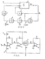
- Figure 5 shows a circuit for tone detection and generation using a programmable state variable filter 10 of the type shown in any of the previous figures.
- the input of the programmable filter 10 is connected via a resistor 11 and capacitor 12 to an input for receiving a decoded audio signal including tones whose frequencies are to be detected.
- the input of the filter 10 is also connected via a resistor 13 and a capacitor 14 to an output of a microprocessor or logic controller 15.
- the microprocessor or logic controller 15 has a command data input 17 and an N-line bus. output 18 connected to the programming inputs of the filter 10.
- the output of the filter 10 is connected to an output 19 of the circuit for supplying an encoded tone output and to the input of a tone detector 20 whose output provides a tone detection output at 21.
- the microprocessor or logic controller 15 sets the resonant frequency of the programmable filter 10, via the bus 18, to the required frequency.
- the tone detector 20 compares the level of the output signal from the filter 10 with a predetermined value so that, when a tone at the resonant frequency of the filter 10 is supplied to the input thereof, the tone detector 20 provides a signal as the output 21 indicating detection of the tone. However, if a tone having a frequency different from the resonant frequency of the filter is received, then the output signal of the tone detector 20 is such as to indicate that a tone having the same frequency as the resonant frequency of the filter 10 is not being received.
- the microprocessor or logic controller 15 supplies a square wave of desired frequency via the capacitor 14 and the resistor 13 to the input of the programmable filter 10.
- the microprocessor or logic controller set the resonent frequency of the filter to the fundamental frequency of the square wave, so that the filter 10 substantially removes the harmonics from the square wave to provide a sine wave output at the output 19 of accurate frequency and of good purity.
- the purity of the sine wave depends upon the Q-factor of the filter.
- the tone thus produced will have a total harmonic distortion of approximately 1.5 percent (a measured value).
- Figure 6 shows another circuit for the detection of tones including a programmable filter 30 of the type shown in any one of Figures 1 to 4.
- the programming input of the filter 30 may be connected to a microprocessor or logic controller, as in the case of the circuit of Figure 5.
- the input of the circuit is connected to the input of the filter 30 and also to a non-inverting input of a summer 31.
- the output of the filter 30 is connected to an inverting input of the summer 31 and also via an envelope detector comprising a diode 32, a resistor 33, and a capacitor 34 to the input of a weighting circuit 35.
- the weighting circuit 35 applies an attenuation or gain to the envelope signal by effectively multiplying the signal by a factor K, which may be larger or smaller than unity.
- the outputof the weighting circuit 35 is connected to one input of a comparator 36 whose other input is connected via a further envelope detecting circuit comprising a diode 37, a resistor 38, and a capacitor 39 to the output of the summer 31.
- the circuit of Figure 6 operates as follows.
- the resonant frequency of the programmable filter 30 is set to the value of a tone to be detected.
- this signal is passed by the filter 30 to the summer 31, which also receives the signal direct from the' input of the circuit.
- the out-of-band signal at the output of the summer 31 has a zero or relatively low value, whereas the in-band signal at the output of the filter has a relatively large value.
- the comparator 36 thus compares the out-of-band signal with the in-band signal, after weighting by the circuit 35, and provides an output signal at the output 40 indicating that a tone of the correct frequency has been received.
- the in-band signal at the output of the filter 30 is of relatively low level whereas the out-of-band signal at the output of the summer 31 is of relatively high value.
- the comparator 36 compares the level of the two signals and provides a signal at the output 40 indicating that the desired tone has not been received.
- circuits of Figures 5 and 6 may be used for the generation and/or detection of audio tones for tone signaling in communication systems. These circuits provide reliable detection of tones of various frequencies and are capable of interfacing simply with microprocessor controllers and the like. Similarly, tones of accurately determined frequency can be generated for signaling purposes with the frequency of the tone being under microprocessor control.
- Figure 7 shows a modification of the tone detecting circuit of Figure 6, in which the differencing circuit is removed and a weighting circuit is provided on the out-of-band signal path.
- attenuation or gain may be applied in the in-band path, however, in practice only gain is required. The same effect is more readily obtained by introducing attenuation, e.g. by means of resistors 40, 41 in the out-of-band path.
- factor k is the attenuation in the out-of-hand path.
- Tone Detection Output T, may be represented by where sgn (signum) represents the operation of the comparator and v and v 0 are signals proportional to the in-band and out-of-band voltages respectively.
- Factor k is an attenuation in the out-of-band signal path.
- V o V - v t where V is the input to the tone detector
- the out-of-band signal V 0 need not be explicitly generated and the differencing stage 31 can be removed from the circuit of Figure 6, giving the circuit of Figure 7.
- a new attenuation factor k 1 given by is established with two resistors and the comparator simply compares the in-band signal with another signal that is k 1 times the input signal.
- Figure 8 shows a circuit for tone generation using a programmable state variable filter 50 of the type shown in any of Figures 1 to 4.
- the input of the programmable filter 50 is connected to the output of a digital-to-analog converter 51 whose digital inputs are connected to an output port of a microprocessor 52 via an N-line bus 53.
- the microprocessor 52 has another output port, connected via an N-line bus 54 to the programming inputs of the filter 50, and a command data input 55.
- the output 56 of the filter 50 forms the output of the tone generation circuit.
- the microprocessor or logic controller 52 supplies a sequence of binary numbers to the converter 51 giving a best approximation of the required sinewave.
- the output of the converter 51 thus comprises a staircase waveform constituting a close approximation to the required sinewave.
- the resonant frequency of the programmable filter 50 is set by the microprocessor or logic controller 52 to the fundamental frequency of the required sinewave so as to filter out the higher harmonics of the staircase waveform. It is thus possible to provide sinewaves having exceedingly low distortion, total harmonic distortion figures of 0.00025 % being achievable.
Landscapes
- Measuring Frequencies, Analyzing Spectra (AREA)
- Tone Control, Compression And Expansion, Limiting Amplitude (AREA)
- Networks Using Active Elements (AREA)
Applications Claiming Priority (2)
| Application Number | Priority Date | Filing Date | Title |
|---|---|---|---|
| GB8230548 | 1982-10-26 | ||
| GB08230548A GB2132046A (en) | 1982-10-26 | 1982-10-26 | Improvements in or relating to state variable filters |
Publications (2)
| Publication Number | Publication Date |
|---|---|
| EP0110555A2 true EP0110555A2 (de) | 1984-06-13 |
| EP0110555A3 EP0110555A3 (de) | 1986-03-05 |
Family
ID=10533840
Family Applications (1)
| Application Number | Title | Priority Date | Filing Date |
|---|---|---|---|
| EP83306519A Withdrawn EP0110555A3 (de) | 1982-10-26 | 1983-10-26 | Zustandsvariable Filter |
Country Status (2)
| Country | Link |
|---|---|
| EP (1) | EP0110555A3 (de) |
| GB (1) | GB2132046A (de) |
Cited By (2)
| Publication number | Priority date | Publication date | Assignee | Title |
|---|---|---|---|---|
| GB2508587A (en) * | 2012-11-30 | 2014-06-11 | Red Lion 49 Ltd | State variable filter for audio equaliser |
| US20250266810A1 (en) * | 2022-09-21 | 2025-08-21 | Metacube Co.,Ltd. | Digital filter circuit, digital filtering method, and storage medium storing digital filtering program |
Families Citing this family (1)
| Publication number | Priority date | Publication date | Assignee | Title |
|---|---|---|---|---|
| RU2169430C1 (ru) * | 2000-07-20 | 2001-06-20 | Таганрогский государственный радиотехнический университет | Программируемый arc-фильтр |
Family Cites Families (6)
| Publication number | Priority date | Publication date | Assignee | Title |
|---|---|---|---|---|
| US2917626A (en) * | 1958-03-10 | 1959-12-15 | Textron Inc | Peak-notch equalizer |
| US3715679A (en) * | 1971-07-29 | 1973-02-06 | Bell Telephone Labor Inc | Active rc delay equalizer |
| US3952288A (en) * | 1974-09-30 | 1976-04-20 | Bell & Howell Company | Multifrequency linear filter networks with active elements |
| SE396684B (sv) * | 1976-02-09 | 1977-09-26 | Ericsson Telefon Ab L M | Hallkrets i en mottagaranordning for mfc-signalering |
| DE2747857C3 (de) * | 1977-10-26 | 1980-07-24 | Karl Heinz Dr.-Ing. 8500 Nuernberg Feistel | Vierpol, dessen Übertragungsfunktion einstellbar ist |
| DE2854978A1 (de) * | 1978-12-20 | 1980-07-10 | Bosch Gmbh Robert | aktives nf-bandpassfilter |
-
1982
- 1982-10-26 GB GB08230548A patent/GB2132046A/en not_active Withdrawn
-
1983
- 1983-10-26 EP EP83306519A patent/EP0110555A3/de not_active Withdrawn
Cited By (5)
| Publication number | Priority date | Publication date | Assignee | Title |
|---|---|---|---|---|
| GB2508587A (en) * | 2012-11-30 | 2014-06-11 | Red Lion 49 Ltd | State variable filter for audio equaliser |
| GB2508587B (en) * | 2012-11-30 | 2015-06-17 | Red Lion 49 Ltd | Equaliser |
| US9154100B2 (en) | 2012-11-30 | 2015-10-06 | Red Lion 49 Limited | Equalizer |
| US20250266810A1 (en) * | 2022-09-21 | 2025-08-21 | Metacube Co.,Ltd. | Digital filter circuit, digital filtering method, and storage medium storing digital filtering program |
| US12603641B2 (en) * | 2022-09-21 | 2026-04-14 | Metacube Co., Ltd. | Digital filter circuit, digital filtering method, and storage medium storing digital filtering program |
Also Published As
| Publication number | Publication date |
|---|---|
| GB2132046A (en) | 1984-06-27 |
| EP0110555A3 (de) | 1986-03-05 |
Similar Documents
| Publication | Publication Date | Title |
|---|---|---|
| EP0080771B1 (de) | Schaltungsanordnung zur Erregung einer oder mehrerer Wandlereinheiten | |
| US4079199A (en) | Acoustic feedback detector and automatic gain control | |
| EP0753938A1 (de) | Frequenzabstimmungsvorrichtung und -verfahren für zeitkontinuierliche Filter | |
| EP0751626A2 (de) | Funksender | |
| JPH0445859B2 (de) | ||
| EP0110555A2 (de) | Zustandsvariable Filter | |
| US5231360A (en) | Multi-range voltage amplifier having multiplying digital/analog converters and programmable filter using multiplying DAC in feedback loop | |
| US5271059A (en) | Method and configuration for forming a line termination of a telephone line | |
| US6625278B1 (en) | Impedance matching with sigma delta filter | |
| US4412189A (en) | Switchable signal compressor/signal expander | |
| US5206603A (en) | Circuit arrangement with electronically controllable transfer characteristic | |
| US4394743A (en) | Tone generation method and apparatus using stored reference calibration coefficients | |
| Chu | A deterministic broad-band signal for acoustical measurements | |
| JPS6238340Y2 (de) | ||
| RU2040853C1 (ru) | Программируемый arc-фильтр | |
| RU2019904C1 (ru) | Программируемый arc-фильтр | |
| US5629647A (en) | Audio amplifier switching noise measuring method and device | |
| JPS5846707A (ja) | 出力レベル制御回路 | |
| US4926473A (en) | Longitudinal balance system | |
| SU1718146A1 (ru) | Преобразователь параметров четырехэлементных двухполюсных цепей | |
| Coates et al. | A general-purpose digital filter using the FAD integrated circuit | |
| JPS56166613A (en) | Voltage to current converting circuit | |
| JP2508455B2 (ja) | 波形デ―タ発生回路 | |
| SU866547A1 (ru) | Источник стабилизированного переменного напр жени | |
| JPS60257612A (ja) | 利得制御可能な集積回路増幅器 |
Legal Events
| Date | Code | Title | Description |
|---|---|---|---|
| PUAI | Public reference made under article 153(3) epc to a published international application that has entered the european phase |
Free format text: ORIGINAL CODE: 0009012 |
|
| AK | Designated contracting states |
Designated state(s): AT BE CH DE FR GB IT LI LU NL SE |
|
| PUAL | Search report despatched |
Free format text: ORIGINAL CODE: 0009013 |
|
| AK | Designated contracting states |
Kind code of ref document: A3 Designated state(s): AT BE CH DE FR GB IT LI LU NL SE |
|
| STAA | Information on the status of an ep patent application or granted ep patent |
Free format text: STATUS: THE APPLICATION IS DEEMED TO BE WITHDRAWN |
|
| 18D | Application deemed to be withdrawn |
Effective date: 19861106 |
|
| RIN1 | Information on inventor provided before grant (corrected) |
Inventor name: RIGGS, WILLIAM Inventor name: THOMAS, LOUIS DAVID |