EP0751626A2 - Funksender - Google Patents
Funksender Download PDFInfo
- Publication number
- EP0751626A2 EP0751626A2 EP96304684A EP96304684A EP0751626A2 EP 0751626 A2 EP0751626 A2 EP 0751626A2 EP 96304684 A EP96304684 A EP 96304684A EP 96304684 A EP96304684 A EP 96304684A EP 0751626 A2 EP0751626 A2 EP 0751626A2
- Authority
- EP
- European Patent Office
- Prior art keywords
- transmission signal
- voltage
- electric power
- circuit
- signal
- Prior art date
- Legal status (The legal status is an assumption and is not a legal conclusion. Google has not performed a legal analysis and makes no representation as to the accuracy of the status listed.)
- Ceased
Links
Images


Classifications
-
- H—ELECTRICITY
- H04—ELECTRIC COMMUNICATION TECHNIQUE
- H04B—TRANSMISSION
- H04B7/00—Radio transmission systems, i.e. using radiation field
- H04B7/24—Radio transmission systems, i.e. using radiation field for communication between two or more posts
- H04B7/26—Radio transmission systems, i.e. using radiation field for communication between two or more posts at least one of which is mobile
-
- H—ELECTRICITY
- H03—ELECTRONIC CIRCUITRY
- H03G—CONTROL OF AMPLIFICATION
- H03G3/00—Gain control in amplifiers or frequency changers
- H03G3/20—Automatic control
- H03G3/30—Automatic control in amplifiers having semiconductor devices
- H03G3/3036—Automatic control in amplifiers having semiconductor devices in high-frequency amplifiers or in frequency-changers
- H03G3/3042—Automatic control in amplifiers having semiconductor devices in high-frequency amplifiers or in frequency-changers in modulators, frequency-changers, transmitters or power amplifiers
-
- H—ELECTRICITY
- H03—ELECTRONIC CIRCUITRY
- H03G—CONTROL OF AMPLIFICATION
- H03G1/00—Details of arrangements for controlling amplification
- H03G1/0005—Circuits characterised by the type of controlling devices operated by a controlling current or voltage signal
- H03G1/0088—Circuits characterised by the type of controlling devices operated by a controlling current or voltage signal using discontinuously variable devices, e.g. switch-operated
-
- H—ELECTRICITY
- H04—ELECTRIC COMMUNICATION TECHNIQUE
- H04B—TRANSMISSION
- H04B1/00—Details of transmission systems, not covered by a single one of groups H04B3/00 - H04B13/00; Details of transmission systems not characterised by the medium used for transmission
- H04B1/02—Transmitters
- H04B1/04—Circuits
- H04B2001/0408—Circuits with power amplifiers
- H04B2001/0416—Circuits with power amplifiers having gain or transmission power control
Definitions
- the present invention relates to a radio transmitter for use with a radio communication system, e.g., as a mobile station of a portable telephone system.
- a telephone system comprises a base station and a mobile station, and a transmission signal power of the mobile station is controlled by transmitting a setting signal for controlling the transmission signal power of the mobile station from the base station to the mobile station.
- a transmission signal power of a mobile station with a maximum transmission signal power of 0.8 W is requested to set the transmission signal power between 0 and -20 dB in steps of 4 dB where the maximum transmission signal power is 0 dB.
- An allowance range of error in control of the transmission signal power of the mobile station is generally determined between +2 dB and -4 dB with respect to the designated control value, and determined between +20 % and -50 % (corresponding to +0.8 dB and -3 dB in case the maximum transmission signal power is 0.8 W) with respect to the maximum transmission signal power.
- FIG. 1 of the accompanying drawings shows a circuit for use with a radio transmitter whose transmission signal power is controlled as described above.
- a transmission signal modulated by a modulator 21 is amplified to a desired electric power by a variable gain amplifier 22, an excitation amplifier 23 and a final-stage amplifier 21, and supplied through a directional coupler 25 to an antenna 26, from which it is radiated.
- a transmission signal distributed by the directional coupler 25 is detected by a detector 27.
- the detector 27 outputs a detected voltage which reflects a transmission signal power supplied to the above antenna 26.
- a control circuit 28 generates a signal for setting a digital-to-analog (D/A) converter 29 in such a way as to generate a reference voltage corresponding to a desired transmission signal power in accordance with the above setting signal.
- D/A converter 29 outputs a reference voltage corresponding to the desired transmission signal power in accordance with the above setting signal.
- the reference voltage from the D/A converter 29 and the detected voltage from the detector 27 are supplied to a subtracter 30, and a subtracted result from the subtracter 30 is supplied through a low-pass filter 31 to a gain control terminal of the variable gain amplifier 22, thereby resulting in a gain of this variable gain amplifier 22 being determined.
- the above-mentioned block forms a feedback loop for determining a transmission signal electric power.
- the low-pass filter 31 for example, is a primary integral type
- this feedback loop responds such that the output from the subtracter 30 becomes 0 [V], and is stabilized when the detected voltage becomes equal to the reference voltage.
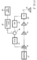
- transfer functions expressed by Laplace transform are defined as shown in FIG. 2, and respective transfer functions are set as follow:
- the transmission signal electric power y(t) can be defined by the reference voltage V.
- the output from the subtracter 30 is converged to 0V, and the feedback loop is stabilized when the detected voltage becomes equal to the reference voltage.
- the transmission signal electric power can be set between +9 dBm and +29 dBm at the step of 4dB.
- the allowable control error of the transmission signal electric power is determined as +0.8 dB/-3 dB with respect to the designated control value in the case of the maximum output, and +2 dB/-4 dB in other cases.
- FIG. 3 shows, by way of example, measured results of high frequency input electric power versus DC output electric power characteristics of the detector 27.
- the output electric power of the detector 27 becomes equal to the reference voltage from the D/A converter 29 based on the equation (6) which describes operation of the above feedback loop. Therefore, from a control standpoint, the vertical and horizontal axes shown in FIG. 4 are replaced with each other, and a relationship between the output voltage and the reference electric power shown in FIG. 4 is considered.
- the changed amount per 1 LSB is as sufficiently small as 0.2 dBm so that the transmission signal electric power can be controlled with a desired accuracy.
- the changed amount per 1 LSB is 2.4 dBm, and the changed amount of one step is considerably large.
- the transmission signal electric power cannot be controlled with a desired accuracy.
- this previously-proposed method causes the circuit scale of the D/A converter to become large, and also causes various problems.
- the conventional circuit can control the transmission signal electric power with a desired accuracy when the transmission signal electric power is large.
- the conventional circuit cannot control the transmission signal electric power with a desired accuracy.
- the resolution in controlling the transmission signal electric power is increased, then the circuit scale of the D/A converter is unavoidably increased, and there arise various problems.
- a transmitter apparatus for transmitting radio waves which is comprised of a variable amplifier for amplifying a signal with a variable amplitude gain, a dividing circuit for dividing a signal to a plurality or directions, a detecting circuit for detecting a signal from the dividing circuit, a reference signal generating circuit for generating a reference signal, a subtracting circuit for subtracting an output signal of the detecting circuit from an output signal of the reference signal generating circuit, an output signal of the subtracting circuit being supplied to the variable amplifier for a gain control signal, wherein the reference signal generating circuit comprises a generating circuit for generating a basic reference signal, a setting circuit for setting a reference signal as stepped values, and a decreasing voltage circuit for decreasing voltages of an output signal of the generating circuit.
- a radio transmitter may therefore be provided in which a reference voltage for controlling a transmission signal electric power to a desired value is set stepwise, the thus set reference voltage is supplied through a predetermined voltage-dividing means and compared with a detected voltage of a transmission signal electric power and the transmission signal electric power is controlled in response to a compared output.
- a radio transmitter in which a modulated signal is amplified by a variable gain amplifier and a power amplifier and supplied to an antenna, a detected voltage which reflects a transmission signal electric power supplied to the antenna is outputted and the detected voltage is compared with an arbitrary reference voltage, the transmission signal electric power is controlled to a predetermined value by controlling the gain of the variable gain amplifier in response to a compared output, a reference voltage is set stepwise, and the thus set reference voltage is processed by a predetermined voltage-dividing means and compared with the detected voltage.
- FIG. 5 is a block diagram showing a transmitter circuit of a mobile station of a portable telephone system to which a radio transmitter according to the present invention is applied.
- a transmission signal modulated by a modulator 1 is amplified by a desired electric power by a variable gain amplifier 2, the excitation amplifier 3 and a final-stage amplifier 4 and supplied through a directional coupler 5 to an antenna 6, from which it is radiated.
- the transmission signal distributed by the directional coupler 5 is detected by a detector 7.
- the detector 7 outputs a detected voltage which reflects the transmission signal electric power supplied to the antenna 6.
- control circuit 8 generates a signal for setting a D/A converter 9 in such a way as to generate a reference voltage corresponding to a desired transmission signal electric power.
- the reference voltage from the D/A converter 9 is supplied to a resistor r 0 and a voltage-dividing circuit 10 of a series circuit of resistors r 1 , r 2 , r 3 and switches s 1 , s 2 , s 3 . These switches s 1 , s 2 , s 3 are turned on and off under control of control signals i, j, k from the control circuit 8.
- the reference voltage divided by the voltage-dividing circuit 10 and the detected voltage from the detector 7 are supplied to a subtracter 11. Further, a subtracted result is supplied through a low-pass filter 12 to the gain control terminal of the variable gain amplifier 2, resulting in the gain of the variable gain amplifier 2 being determined.
- the reference voltage from the D/A converter 9 is divided by the resistor r 0 and the resistors r 1 , r 2 , r 3 selected by the control signals. Therefore, if resistance values of these resistors r 0 , r 1 , r 2 , r 3 are determined arbitrarily, then the characteristic of the reference voltage divided by the voltage-dividing circuit 10 can be made close to that of the detector 7, and hence the accuracy in setting can be increased.
- V 0 1 1 + r 4 a 4 i + 2 j + k V
- the output voltage of the D/A converter 9 is divided by the voltage-dividing circuit 10.
- the reference voltage when the transmission signal electric power is large, or the reference voltage is high, the reference voltage is set coarsely.
- the reference voltage can be set fine.
- the transmission signal electric power when the transmission signal electric power is large, the transmission signal electric power can be controlled with a desired accuracy, however, when the transmission signal electric power becomes small, the transmission signal electric power cannot be controlled with a desired accuracy. Further, when the resolution in controlling the transmission signal electric power is increased, there arise various problems such as the increased circuit scale of D/A converter.
- the reference voltage for controlling the transmission signal electric power to a predetermined value is set stepwise, the thus set reference voltage is outputted from the predetermined voltage-dividing means and compared with the detected voltage of the transmission signal electric power, and the transmission signal electric power is controlled in response to the compared output, whereby a desired accuracy can be obtained regardless of the magnitude of the transmission signal electric power. Furthermore, there is then no risk that the circuit scale of the D/A converter is increased. Therefore, the transmission signal electric power can be controlled satisfactorily by the simple arrangement.
- the radio transmitter in which the modulated signal is amplified by the variable gain amplifier and the power amplifier and supplied to the antenna, the detected voltage which reflects a transmission signal electric power supplied to the antenna is outputted and the detected voltage is compared with an arbitrary reference voltage, the transmission signal electric power is controlled to a predetermined value by controlling the gain of the variable gain amplifier in response to a compared output.
- the reference voltage is set stepwise, and the thus set reference voltage is processed by a predetermined voltage-dividing means and compared with the detected voltage. Therefore, a desired accuracy can be obtained regardless of the magnitude of the transmission signal electric power. Furthermore, there is then no risk that the circuit scale of the D/A converter is increased. Therefore, the transmission signal electric power can be controlled satisfactorily by the simple arrangement.
- the use of the radio transmitter according to the present invention is not limited to the transmitting circuit of the mobile station in the portable telephone system, for example.
- the radio transmitter according to the present invention is applied to the transmitting circuit of the mobile station in the portable telephone system, the standard is not limited to the aforementioned STD-27 of Japanese digital cellular phone system standardized by Foundation of Radio System Research Center, and the present invention may be applied other digital cellular phone systems, such as IS-54, IS-95 for North America and GMS system for European countries.
- the transmission signal electric power when the transmission signal electric power is large, the transmission signal electric power can be controlled with a desired accuracy, however, when the transmission signal electric power becomes small, the transmission signal electric power cannot be controlled with a desired accuracy. Further, when the resolution in controlling the transmission signal electric power is increased, there arise various problems such as the increased circuit scale of D/A converter.
- the reference voltage for controlling the transmission signal electric power to a predetermined value is set stepwise, the thus set reference voltage is outputted from the predetermined voltage-dividing means and compared with the detected voltage of the transmission signal electric power, and the transmission signal electric power is controlled in response to the compared output, whereby a desired accuracy can be obtained regardless of the magnitude of the transmission signal electric power. Furthermore, there is then no risk that the circuit scale of the D/A converter is increased. Therefore, the transmission signal electric power can be controlled satisfactorily by the simple arrangement.
- the circuit scale of the whole of the apparatus can be reduced, and there can be provided an inexpensive and highly-accurate apparatus.
Landscapes
- Engineering & Computer Science (AREA)
- Computer Networks & Wireless Communication (AREA)
- Signal Processing (AREA)
- Transmitters (AREA)
- Mobile Radio Communication Systems (AREA)
Applications Claiming Priority (2)
| Application Number | Priority Date | Filing Date | Title |
|---|---|---|---|
| JP7160983A JPH0918358A (ja) | 1995-06-27 | 1995-06-27 | 無線送信機 |
| JP160983/95 | 1995-06-27 |
Publications (2)
| Publication Number | Publication Date |
|---|---|
| EP0751626A2 true EP0751626A2 (de) | 1997-01-02 |
| EP0751626A3 EP0751626A3 (de) | 1999-05-19 |
Family
ID=15726346
Family Applications (1)
| Application Number | Title | Priority Date | Filing Date |
|---|---|---|---|
| EP96304684A Ceased EP0751626A3 (de) | 1995-06-27 | 1996-06-25 | Funksender |
Country Status (5)
| Country | Link |
|---|---|
| US (1) | US5826177A (de) |
| EP (1) | EP0751626A3 (de) |
| JP (1) | JPH0918358A (de) |
| KR (1) | KR970004470A (de) |
| CN (1) | CN1146670A (de) |
Cited By (1)
| Publication number | Priority date | Publication date | Assignee | Title |
|---|---|---|---|---|
| US6650278B2 (en) * | 1999-06-29 | 2003-11-18 | Matsushita Electric Industrial Co., Ltd. | Method and device for setting a communications area of a road antenna apparatus |
Families Citing this family (14)
| Publication number | Priority date | Publication date | Assignee | Title |
|---|---|---|---|---|
| JPH11177444A (ja) * | 1997-12-15 | 1999-07-02 | Matsushita Electric Ind Co Ltd | 送信電力制御装置及び方法 |
| FI982561A7 (fi) | 1998-11-26 | 2000-05-27 | Nokia Corp | Tehonsäätömenetelmä ja tehonsäätöjärjestelmä |
| US6353364B1 (en) * | 1998-12-22 | 2002-03-05 | Ericsson Inc. | Digitally gain controllable amplifiers with analog gain control input, on-chip decoder and programmable gain distribution |
| US6480061B2 (en) * | 1999-01-13 | 2002-11-12 | Nortel Networks Limited | Amplifier having digital micro processor control apparatus |
| US6920334B1 (en) | 2000-03-24 | 2005-07-19 | International Business Machines Corporation | Method and apparatus for providing gain control feedback in RF amplifiers |
| US7035609B1 (en) * | 2001-09-24 | 2006-04-25 | Fry Terry L | Method and apparatus for automatically identifying an antenna connected to a radio transmitter and for automatically controlling a transmitter |
| US7260367B2 (en) * | 2002-01-23 | 2007-08-21 | Analog Devices, Inc. | Edge power detector/controller |
| US6741840B2 (en) * | 2002-03-13 | 2004-05-25 | Motorola, Inc. | RF transmitters with saturation detection and correction and methods therefor |
| FI20020990A7 (fi) * | 2002-05-27 | 2003-11-28 | Nokia Corp | Menetelmä signaalin tehon säätämiseksi radiojärjestelmän lähettimessä ja radiojärjestelmän lähetin |
| JP3907052B2 (ja) | 2003-03-07 | 2007-04-18 | ソニー・エリクソン・モバイルコミュニケーションズ株式会社 | 通信端末装置及び増幅回路 |
| US7228114B2 (en) * | 2003-05-21 | 2007-06-05 | Harris Stratex Networks Operating Corporation | Wide dynamic range power detection scheme |
| JP2005229197A (ja) * | 2004-02-10 | 2005-08-25 | Matsushita Electric Ind Co Ltd | 電力増幅器モジュール |
| US20070176665A1 (en) * | 2006-02-01 | 2007-08-02 | Analog Devices, Inc. | Variable voltage attenuator circuits |
| US8829997B1 (en) | 2012-10-23 | 2014-09-09 | M/A-Com Technology Solutions Holdings, Inc. | Monolithic integrated power regulation for power control and/or bias control |
Family Cites Families (10)
| Publication number | Priority date | Publication date | Assignee | Title |
|---|---|---|---|---|
| US5175875A (en) * | 1989-04-02 | 1992-12-29 | Sony Corporation | Radio communication apparatus with programmable signal modulation |
| US5126686A (en) * | 1989-08-15 | 1992-06-30 | Astec International, Ltd. | RF amplifier system having multiple selectable power output levels |
| JPH07101852B2 (ja) * | 1990-06-08 | 1995-11-01 | 三菱電機株式会社 | 送信電力制御回路 |
| US5099204A (en) * | 1990-10-15 | 1992-03-24 | Qualcomm Incorporated | Linear gain control amplifier |
| DE69222893T2 (de) * | 1991-06-18 | 1998-03-05 | Fujitsu Ltd | Digital-Analog-Umsetzer mit Widerstandsnetzwerken |
| TW225619B (de) * | 1991-07-19 | 1994-06-21 | Nippon Electric Co | |
| US5321721A (en) * | 1991-09-13 | 1994-06-14 | Sony Corporation | Spread spectrum communication system and transmitter-receiver |
| JPH06260866A (ja) * | 1993-03-04 | 1994-09-16 | Mitsubishi Electric Corp | 自動出力電力制御回路装置 |
| JP3192323B2 (ja) * | 1994-07-29 | 2001-07-23 | 沖電気工業株式会社 | 電力制御回路 |
| DE69529395T2 (de) * | 1994-12-29 | 2003-11-20 | At & T Corp., New York | Leistungsverstärker mit grosser Dynamik |
-
1995
- 1995-06-27 JP JP7160983A patent/JPH0918358A/ja active Pending
-
1996
- 1996-06-21 US US08/670,747 patent/US5826177A/en not_active Expired - Fee Related
- 1996-06-25 KR KR1019960023496A patent/KR970004470A/ko not_active Withdrawn
- 1996-06-25 EP EP96304684A patent/EP0751626A3/de not_active Ceased
- 1996-06-27 CN CN96110793A patent/CN1146670A/zh active Pending
Cited By (1)
| Publication number | Priority date | Publication date | Assignee | Title |
|---|---|---|---|---|
| US6650278B2 (en) * | 1999-06-29 | 2003-11-18 | Matsushita Electric Industrial Co., Ltd. | Method and device for setting a communications area of a road antenna apparatus |
Also Published As
| Publication number | Publication date |
|---|---|
| EP0751626A3 (de) | 1999-05-19 |
| JPH0918358A (ja) | 1997-01-17 |
| US5826177A (en) | 1998-10-20 |
| CN1146670A (zh) | 1997-04-02 |
| KR970004470A (ko) | 1997-01-29 |
Similar Documents
| Publication | Publication Date | Title |
|---|---|---|
| EP0751626A2 (de) | Funksender | |
| US5303395A (en) | Power control with a constant gain amplifier for portable radio transceivers | |
| US4602218A (en) | Automatic output control circuitry for RF power amplifiers with wide dynamic range | |
| US4709403A (en) | Apparatus for controlling output power of transmitter | |
| KR100291413B1 (ko) | 이동통신단말기의송신전력제어장치 | |
| KR960002390B1 (ko) | 전력 증폭 회로 | |
| US4523155A (en) | Temperature compensated automatic output control circuitry for RF signal power amplifiers with wide dynamic range | |
| US5423081A (en) | Cellular power amplifier power level control circuitry | |
| EP0720287B1 (de) | Leistungsverstärker mit grosser Dynamik | |
| US6807403B2 (en) | Radio telephone apparatus | |
| US5029298A (en) | Transmitter circuit | |
| US4521912A (en) | Low power indicating circuit for a radio transmitter | |
| US4754231A (en) | Automatic control circuitry for a signal power amplifier | |
| US5507022A (en) | Electric field level detecting apparatus | |
| US6236841B1 (en) | Transmission output power control circuit for controlling each of antennas to optimal states | |
| EP0388895B1 (de) | Sender mit variabler Sendeleistung | |
| EP0532203B1 (de) | Vorrichtung zur Leistungssteuerung | |
| US5302913A (en) | Power amplifying circuit capable of producing an output signal having a desired waveform | |
| KR100390666B1 (ko) | 가변 이득 전력 증폭기에 이득 제어 신호를 제공하는 방법및 가변 이득 전력 증폭기 출력 시스템 | |
| JPH0449298B2 (de) | ||
| EP0460280B1 (de) | Schaltung zur Steuerung der Sendeleistung | |
| EP0446073B1 (de) | Verfahren zur Genauigkeitsverbesserung von Leistungsregelung in einem Funktelefon | |
| EP0528689B1 (de) | Detektor | |
| US4412189A (en) | Switchable signal compressor/signal expander | |
| JP2001211125A (ja) | 検波回路 |
Legal Events
| Date | Code | Title | Description |
|---|---|---|---|
| PUAI | Public reference made under article 153(3) epc to a published international application that has entered the european phase |
Free format text: ORIGINAL CODE: 0009012 |
|
| AK | Designated contracting states |
Kind code of ref document: A2 Designated state(s): DE FR GB |
|
| PUAL | Search report despatched |
Free format text: ORIGINAL CODE: 0009013 |
|
| AK | Designated contracting states |
Kind code of ref document: A3 Designated state(s): DE FR GB |
|
| 17P | Request for examination filed |
Effective date: 19991022 |
|
| 17Q | First examination report despatched |
Effective date: 20010219 |
|
| GRAG | Despatch of communication of intention to grant |
Free format text: ORIGINAL CODE: EPIDOS AGRA |
|
| STAA | Information on the status of an ep patent application or granted ep patent |
Free format text: STATUS: THE APPLICATION HAS BEEN REFUSED |
|
| 18R | Application refused |
Effective date: 20021130 |