EP0110652A1 - Anlage und Verfahren zum Walzen und Behandeln von Stahldraht - Google Patents
Anlage und Verfahren zum Walzen und Behandeln von Stahldraht Download PDFInfo
- Publication number
- EP0110652A1 EP0110652A1 EP83307109A EP83307109A EP0110652A1 EP 0110652 A1 EP0110652 A1 EP 0110652A1 EP 83307109 A EP83307109 A EP 83307109A EP 83307109 A EP83307109 A EP 83307109A EP 0110652 A1 EP0110652 A1 EP 0110652A1
- Authority
- EP
- European Patent Office
- Prior art keywords
- air
- rollers
- rod
- conveyor
- rings
- Prior art date
- Legal status (The legal status is an assumption and is not a legal conclusion. Google has not performed a legal analysis and makes no representation as to the accuracy of the status listed.)
- Granted
Links
- 229910000831 Steel Inorganic materials 0.000 title claims abstract description 22
- 239000010959 steel Substances 0.000 title claims abstract description 22
- 238000000034 method Methods 0.000 title claims abstract description 19
- 238000005096 rolling process Methods 0.000 title description 10
- 238000001816 cooling Methods 0.000 claims abstract description 66
- 238000010438 heat treatment Methods 0.000 claims abstract description 18
- 239000000969 carrier Substances 0.000 claims abstract 6
- 238000000137 annealing Methods 0.000 claims description 11
- 238000005098 hot rolling Methods 0.000 claims description 2
- 238000000151 deposition Methods 0.000 claims 2
- 238000007664 blowing Methods 0.000 claims 1
- 239000002131 composite material Substances 0.000 claims 1
- 229910052799 carbon Inorganic materials 0.000 description 17
- OKTJSMMVPCPJKN-UHFFFAOYSA-N Carbon Chemical compound [C] OKTJSMMVPCPJKN-UHFFFAOYSA-N 0.000 description 13
- 238000011282 treatment Methods 0.000 description 10
- 238000010583 slow cooling Methods 0.000 description 8
- 230000008901 benefit Effects 0.000 description 6
- 230000008569 process Effects 0.000 description 6
- 230000008859 change Effects 0.000 description 4
- 238000009434 installation Methods 0.000 description 4
- 230000009466 transformation Effects 0.000 description 4
- XLYOFNOQVPJJNP-UHFFFAOYSA-N water Substances O XLYOFNOQVPJJNP-UHFFFAOYSA-N 0.000 description 4
- 229910045601 alloy Inorganic materials 0.000 description 3
- 239000000956 alloy Substances 0.000 description 3
- 239000000498 cooling water Substances 0.000 description 3
- 229910000734 martensite Inorganic materials 0.000 description 3
- 239000002184 metal Substances 0.000 description 3
- 125000006850 spacer group Chemical group 0.000 description 3
- 238000005279 austempering Methods 0.000 description 2
- 239000011810 insulating material Substances 0.000 description 2
- 230000007246 mechanism Effects 0.000 description 2
- 230000000704 physical effect Effects 0.000 description 2
- 238000005496 tempering Methods 0.000 description 2
- 229910000851 Alloy steel Inorganic materials 0.000 description 1
- 229910001209 Low-carbon steel Inorganic materials 0.000 description 1
- 230000001133 acceleration Effects 0.000 description 1
- 230000009471 action Effects 0.000 description 1
- 229910001566 austenite Inorganic materials 0.000 description 1
- 229910001563 bainite Inorganic materials 0.000 description 1
- 238000006243 chemical reaction Methods 0.000 description 1
- 239000012141 concentrate Substances 0.000 description 1
- 239000000470 constituent Substances 0.000 description 1
- 210000004907 gland Anatomy 0.000 description 1
- 230000017525 heat dissipation Effects 0.000 description 1
- 239000000463 material Substances 0.000 description 1
- 238000012986 modification Methods 0.000 description 1
- 230000004048 modification Effects 0.000 description 1
- 230000003647 oxidation Effects 0.000 description 1
- 238000007254 oxidation reaction Methods 0.000 description 1
- 230000002028 premature Effects 0.000 description 1
- 239000011819 refractory material Substances 0.000 description 1
- 238000003303 reheating Methods 0.000 description 1
- 230000003014 reinforcing effect Effects 0.000 description 1
- 238000009877 rendering Methods 0.000 description 1
- 239000007787 solid Substances 0.000 description 1
Images


Classifications
-
- C—CHEMISTRY; METALLURGY
- C21—METALLURGY OF IRON
- C21D—MODIFYING THE PHYSICAL STRUCTURE OF FERROUS METALS; GENERAL DEVICES FOR HEAT TREATMENT OF FERROUS OR NON-FERROUS METALS OR ALLOYS; MAKING METAL MALLEABLE, e.g. BY DECARBURISATION OR TEMPERING
- C21D9/00—Heat treatment, e.g. annealing, hardening, quenching or tempering, adapted for particular articles; Furnaces therefor
- C21D9/52—Heat treatment, e.g. annealing, hardening, quenching or tempering, adapted for particular articles; Furnaces therefor for wires; for strips ; for rods of unlimited length
- C21D9/54—Furnaces for treating strips or wire
- C21D9/56—Continuous furnaces for strip or wire
- C21D9/573—Continuous furnaces for strip or wire with cooling
- C21D9/5732—Continuous furnaces for strip or wire with cooling of wires; of rods
-
- C—CHEMISTRY; METALLURGY
- C21—METALLURGY OF IRON
- C21D—MODIFYING THE PHYSICAL STRUCTURE OF FERROUS METALS; GENERAL DEVICES FOR HEAT TREATMENT OF FERROUS OR NON-FERROUS METALS OR ALLOYS; MAKING METAL MALLEABLE, e.g. BY DECARBURISATION OR TEMPERING
- C21D9/00—Heat treatment, e.g. annealing, hardening, quenching or tempering, adapted for particular articles; Furnaces therefor
- C21D9/52—Heat treatment, e.g. annealing, hardening, quenching or tempering, adapted for particular articles; Furnaces therefor for wires; for strips ; for rods of unlimited length
- C21D9/54—Furnaces for treating strips or wire
- C21D9/56—Continuous furnaces for strip or wire
Definitions
- This invention relates to methods and apparatus for cooling and treating hot rolled steel rod directly after rolling for the purpose of controlling the physical properties of the product. More particularly it relates to methods and apparatus adapted for improved control and versatility of cooling and/or treating hot rolled steel rod of widely differing sizes and steel chemistries.
- That process produced steel rod in the low carbon content range (i.e..03%C to .20%C) which, in some instances, could be processed to finished product without heat treatment, but in many other instances, required annealing or similar treatment. In the low alloy and high alloy content grades, further heat treatment was invariably required.
- a basic object of this invention therefore, is to provide, in one and the same piece of equipment, a maximum range of treatment options and an ability for changes from any option to any other with a minimum of inconvenience. More specifically, an object of the invention is to provide equipment adapted for slow cooling, which offers the options of IRC, annealing, austempering, martempering and the like with or without preliminary water cooling and also adapted for rapid cooling together with means for maintaining a relatively cool conveyor and providing a greater intensity and more effective air cooling flow than was available in prior equipments. A further object is to provide the foregoing together with push-button control for rapid change from any one option to any other.
- a preferred embodiment of the invention selected for purposes of illustration comprises a steel rod rolling mill preferably adapted for high speed rolling (i.e. +20,000 fpm-6,100 metres per second).
- Conventional water cooling is provided in the delivery pipes at the output end of the mill, followed by means for laying the rod in spread-out ring form onto a moving conveyor.
- the conveyor is a roller conveyor and is provided with pivotally mounted (and hence removable), insulated covers provided with heating elements which may be as described in U.S. Patent No. 3930900.
- electrical resistance heating elements or other form of heating element, as desired
- a cooling air application means is provided in association with each roller along the conveyor.
- the water cooling means, the means for pivoting the covers into and out of operation, the heating elements, the cooling air application means, and the conveyor speed, are each individually remotely controllable such that all treatment options can be intitiated by "push-button" operation from a remote control station.
- Remotely recording temperature sensing elements are located throughout the equipment so that operations can be monitored.
- the equipment can be controlled to cool the rod very rapidly in the delivery pipes so as to form a partially martensitic structure, simply by calling for maximum cooling water in the delivery pupes, and that the rod can thereafter be readily tempered as desired (as in U.S. pat. no. 3711238) by lowering the covers and turning on and adjusting the temperature of as many of the heating elements as desired. Also if slow, uniform cooling is desired, the covers can be lowered, the conveyor speed can be reduced so as to build the rings into a dense lay, and IRC can be practiced by commanding the application of heat at specific points along the conveyor pursurant to temperature indications from the remotely recording thermometers.
- air supply plenum chambers are provided beneath the rollers and heaters (as in U.S. Patent No. 3930900) communicating with and supplying cooling air to slotted orifices directly under each roller.
- the cooling air which may be supplied at different pressures along the length of each roller, is projected directly against the underside of each roller which divides its flow path such that the cooling air stream conforms to the surface of the rollers and converges at the top of the rollers against the overlying rod rings.
- the cooling air is heated prior to its reaching the rod.
- This causes a preliminary expansion of the air (per the Law of Charles, at atmospheric pressure, air doubles its volume for every 273 0 C of increase of temperature),prior to its reaching the rod, which expansion also causes an acceleration of the velocity of the air stream which adds to the impinging force of cooling air against the rod.
- guides are provided around the rollers to channel the cooling air from an orifice directly below the roller to the top of the roller and force it to impinge directly against the rod rings.
- the rollers are perforated or slotted and the cooling air is blown into one end of the rollers and out of the top of the rollers through the perforations directly into the dense lay of the rings.
- the concentration of the air at the perforations at the top of the rollers is accomplished by a fixed baffel around the roller.
- the embodiments which bring the forced-air orifices directly against the underside of the lay are advantageous because, only in this way, can the cooling air penetrate the dense parts of the lay. This is because of the expansion factor mentioned above.
- the cooling air at 20°C contacts the rod at 1000°C the air must either expand to over three times its volume or its pressure must increase. Some of both reactions actually take place. The air cannot escape freely through the tightly packed strands and, therefore, its pressure increases along with its temperature increase. If the air application orifice is not held directly against the lay, the back-pressure simply retards further progress of the cooling air through the lay, and slow cooling results at the dense cross-overs as has been observed in typical Stelmor installations for many years.
- rollers are exposed only very briefly to the concentrated radiant heat of the rod rings, and that they only contact the rings for a small fraction of a second. In this way heat build-up at the surface of the rollers and premature heating of the cooling air are minimized.
- shielded perforated or slotted roller embodiments Another feature of the shielded perforated or slotted roller embodiments is that larger diameter rollers with less space between them can be used. This makes possible a better conveying action by the rollers, for the rings and greater heat dissipation from the surface of the rollers between exposures to the heat of the rings.
- An illustrative embodiment of the present invention shown diagrammatically in Figure 1, comprises a conveyor indicated generally at 10 adapted to receive hot rolled steel rod issuing from a rolling mill (not shown) at high speed (+20,000 fpm, 6,100 metres per second), through a delivery pipe 12 which is equipped (optionally) to apply cooling water to the rod to cool it from rolling temperature (c 1000°C to 1100°C) down to a surface temperture as low as 550°C.
- the hot rolled rod is then passed through a laying head 14 which coils the rod into rings and lays them onto an endless wire mesh belt, run-in portion 16 of conveyor 10, which, due to its forward motion, spreads the falling rod out into rings 18.
- the laying head 14 herein shown coils the rings on a vertical axis, it will be understood that coiling on a tilted or horizontal axis is also intended and the horizontal axis is preferred for high delivery speeds.
- the conveyor 10 may be equipped with insulated and heated covers 20, 22, 24, 26, 28 and 30 as shown in Figure 1.
- blowers 32 are mounted below each conveyor section and are equipped to supply cooling air to the rod through plenum chambers 42. These chambers can be baffled across the conveyor, to provide a multiplicity of plenum 42a, 42b and 42c, (see Figure 8 ), each of which can be supplied by different blowers so that greater pressure can be supplied to the rod along the edges of the conveyor where the lay is more dense.
- Heat is applied to the covers 20, 22 etc., at 34a, 34b etc.
- Conveyor 10 terminates with a wire mesh belt, run-out portion 36 which conveys the rings 18 to a collecting device 37.
- the conveyor 10 comprises spaced, driven rollers 38, each of which, as shown in Figure 2, is supplied with cooling air from fans 32 through small plenums 40 which communicate with fans 32 through larger plenums 42.
- Heaters 44 which may be electrical resistance elements as shown, or larger gas fired radiant heating elements, mounted over refractory material 46 are located between each pair of rollers 38.
- Plenums 40 Air, under pressure in plenums 40, passes upwardly though slots 48, around rollers 38 and then impinges against the undersurface of rings 18.
- Plenums 40 can be sectioned across the conveyor and slots 48 can be provided with vanes for adjusting the widths of different slots in different sections so as to vary the air application across the rings if desired.
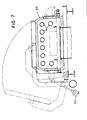
- Additional heat for either retarded cooling or for heat treating may be supplied through gas-fired radiant heating tubes 50 carried by covers 20, 22, etc. as shown in Figure 7. Covers 20, 22, etc. are also provided with remotely controllable pneumatic mechanism 52 for automatically pivoting them into or out of operative position.
- each plenum 40 Remotely recording heat and pressure indicating instruments are provided in each plenum 40, along the conveyor at closely spaced intervals along the conveyor 10 within the insulated (and heated) pivotally mounted covers 20, 22 etc., the air plenums 40 and adjacent to heating elements 44 and 50.
- Each element is individually remotely operable such that a wide variety of treatments can be performed under push-button control from a remote station.
- treatments feasible are (a) extremely slow cooling (e.g..2°C/sec) of a closely packed lay (i.e.
- FIG. 3 Alternate means for applying the cooling air to the rod are shown in Figures 3 to 6.
- Figure 3 means are shown for admitting air under pressure to the interior of rollers 38 through ducts 54 and slots 56 at one end of each roller 38.
- Ducts 54 are stationary and the escape of air is prevented by gland seals 58.
- rollers 38 are perforated at 60 in the areas where the rings 18 come in contact with rollers 38. Air passing through perforations impinges against the rod rings 18.
- the air may be concentrated against the rod by a cylindrical shield 62 which prevents the escape of air except upwardly (see shield 62 of Figure 4 with enclosed bottom along dotted lines).
- Axial flow, or turbine type, air compressors may be used to increase the air pressure and also individually to control each air application station.
- FIG 4 A further alternative is shown in Figure 4, in which air from plenums 40 is channelled through rollers 38 passing into perforations 60 at the bottom of each roller and outwardly at the top.
- This embodiment has the advantage of using the cooling air to cool the rollers 38. It also can be sectioned so as to confine the air application longitudinally of the rollers 38 so as to make sure that air destined for the dense part of the lay is not deflected laterally.
- Still another embodiment shown in Figures 5 and 6, employs a solid shaft 63 onto which are mounted disks 64 separated by spacers 66 at intervals along the shaft 63 with threaded headers at the shaft ends to hold them together.
- a shield 68 is employed which has fingers 70 extending upwardly between disks 64 at the top of the rollers positioned to channel the air and concentrate it against the rod.
- This embodiment has the advantage of providing a larger arc of roll contact in case a portion of rod rings 18 happens to sag down. It also has a very small area of contact (or exposure) betwen the hot rod and the roller surface which area of contact can be serrated for better traction.
- This coupled with applying the cooling air both to the disks 64 and to the insides of shield elements 68 and 70, helps keep the rollers cool and makes the air cooling more efficient.
- This embodiment also permits the application of cooling air at different pressures and independently such that back-pressure at any given point does not cause a stoppage of air flow.
- Another advantage of this embodiment has to do with the materials out of which the rollers are made.
- expensive, heat resistant, steels must be used for the rollers to accommodate the high heat of the retarded cooling and heat treatment modes of operation.
- a rim of expensive metal on disks 64 is all that is needed, and shafts 63, spacers 66, and the remainder of disks 64 can be made of less expensive metal.
- a sleeve of insulating material surrounding shaft 63 can be employed.
- spacers 66 can be made of insulating material.
- the shaft 63 can be hollow and adapted for the circulation of cooling water through it. While rollers as shown in Figures 3 to 6 and described, bear a special cooperative relationship to the related and surrounding structures, they also present unique advantages in themselves, and therefore, we intend to claim them both alone and in combination.
- the apparatus of the invention provides a wide range of treatment options within one and the same piece of equipment all on a single treating line and all at push-button control.
- the operator can operate the conveyor in an intermittent manner so as to form spaced, relatively large, stacked bundles with only a few connecting rings in between.
- treatments such as subcritical, full, isothermal, and cycle annealing can be simulated, but with the advantage of avoiding the time and energy required in those processes to heat the rod.
- the time available for treatment depends upon rolling speed, the conveyor speed, the concentration of metal on the conveyor and the length of the conveyor.
- a 300' (91.4 metres) conveyor moving a 5 fpm (1.52 metres per second) can subject the rod to treatment for one hour, which is adequate for many types of annealing when a reheating cycle is not involved.
- an immediate (labour free) change to the rapid cooling modes of operation can be made.
Landscapes
- Chemical & Material Sciences (AREA)
- Engineering & Computer Science (AREA)
- Organic Chemistry (AREA)
- Thermal Sciences (AREA)
- Crystallography & Structural Chemistry (AREA)
- Mechanical Engineering (AREA)
- Materials Engineering (AREA)
- Metallurgy (AREA)
- Physics & Mathematics (AREA)
- Heat Treatments In General, Especially Conveying And Cooling (AREA)
- Heat Treatment Of Strip Materials And Filament Materials (AREA)
- Heat Treatment Of Steel (AREA)
- Heat Treatment Of Articles (AREA)
- Metal Rolling (AREA)
- Chemical Treatment Of Metals (AREA)
- Pressure Welding/Diffusion-Bonding (AREA)
- Press Drives And Press Lines (AREA)
Priority Applications (1)
| Application Number | Priority Date | Filing Date | Title |
|---|---|---|---|
| AT83307109T ATE27831T1 (de) | 1982-11-22 | 1983-11-21 | Anlage und verfahren zum walzen und behandeln von stahldraht. |
Applications Claiming Priority (2)
| Application Number | Priority Date | Filing Date | Title |
|---|---|---|---|
| US06/443,618 US4448401A (en) | 1982-11-22 | 1982-11-22 | Apparatus for combined hot rolling and treating steel rod |
| US443618 | 1982-11-22 |
Publications (2)
| Publication Number | Publication Date |
|---|---|
| EP0110652A1 true EP0110652A1 (de) | 1984-06-13 |
| EP0110652B1 EP0110652B1 (de) | 1987-06-16 |
Family
ID=23761523
Family Applications (1)
| Application Number | Title | Priority Date | Filing Date |
|---|---|---|---|
| EP83307109A Expired EP0110652B1 (de) | 1982-11-22 | 1983-11-21 | Anlage und Verfahren zum Walzen und Behandeln von Stahldraht |
Country Status (11)
| Country | Link |
|---|---|
| US (1) | US4448401A (de) |
| EP (1) | EP0110652B1 (de) |
| JP (1) | JPS59125211A (de) |
| AT (1) | ATE27831T1 (de) |
| AU (1) | AU560230B2 (de) |
| BR (1) | BR8306296A (de) |
| CA (1) | CA1221562A (de) |
| DE (1) | DE3372109D1 (de) |
| ES (1) | ES526798A0 (de) |
| IN (1) | IN159864B (de) |
| ZA (1) | ZA836621B (de) |
Cited By (3)
| Publication number | Priority date | Publication date | Assignee | Title |
|---|---|---|---|---|
| EP0181101A3 (en) * | 1984-10-31 | 1988-04-06 | Morgan Construction Company | Apparatus and method for air cooling hot rolled steel rod |
| EP0942069A1 (de) * | 1998-03-10 | 1999-09-15 | Sms Schloemann-Siemag Aktiengesellschaft | Kühlschacht für einen Rollgang |
| CN103008370A (zh) * | 2012-12-11 | 2013-04-03 | 西安建筑科技大学 | 一种提高热轧带肋盘螺强度的控冷方法 |
Families Citing this family (8)
| Publication number | Priority date | Publication date | Assignee | Title |
|---|---|---|---|---|
| US4546957A (en) * | 1982-11-22 | 1985-10-15 | Morgan Construction Company | Apparatus for combined hot rolling and treating steel rod |
| IN164702B (de) * | 1984-10-09 | 1989-05-13 | Morgan Construction Co | |
| US5121902A (en) * | 1984-10-09 | 1992-06-16 | Morgan Construction Company | Apparatus for cooling hot rolled steel rod using a plurality of air and water cooled sections |
| IT1210310B (it) * | 1987-06-19 | 1989-09-14 | Alberto Albonetti | Parete radiante,in particolare per scambiatori,forni a muffola esimili |
| US5196156A (en) * | 1991-11-07 | 1993-03-23 | Engineered Production Increase, Inc. | Rod cooling system |
| DE10107566B4 (de) * | 2001-02-17 | 2007-09-27 | Sms Demag Ag | Verfahren und Vorrichtung zum Kühlen sich überlappender Drahtwindungen beim Transport über ein Kühlbett durch Anblasen mit Kühlluft |
| ITPR20050053A1 (it) * | 2005-09-16 | 2007-03-17 | Imas Spa Ind Meccanica | Essiccatoio orizzontale per materiali ceramici in genere e procedimento cosi' ottenuto. |
| EP3383561B1 (de) * | 2015-12-04 | 2024-01-24 | Arconic Technologies LLC | Verfahren zur kühlung einer elektrisch leitenden schicht während einer transversalflussinduktionswärmebehandlung |
Citations (10)
| Publication number | Priority date | Publication date | Assignee | Title |
|---|---|---|---|---|
| US2492942A (en) * | 1949-01-26 | 1949-12-27 | R S Products Corp | Roller hearth furnace |
| US3231432A (en) * | 1964-10-08 | 1966-01-25 | Morgan Construction Co | Process for the quenching of hot rolled rods in direct sequence with rod mill |
| GB1173037A (en) * | 1967-07-21 | 1969-12-03 | Templeborough Rollis Mills Ltd | Process and apparatus for Cooling Hot-Rolled Steel Rod |
| US3649381A (en) * | 1970-01-15 | 1972-03-14 | John T Mayhew | Guide roll construction and utilization |
| US3930900A (en) * | 1974-10-21 | 1976-01-06 | Morgan Construction Company | Process for cooling hot rolled steel rod |
| US3940961A (en) * | 1974-11-18 | 1976-03-02 | Morgan Construction Company | Apparatus for cooling hot rolled steel rod by forced air convection or by supplying heat |
| US3940967A (en) * | 1975-01-10 | 1976-03-02 | Morgan Construction Company | Apparatus for controlled cooling hot rolled steel rod in direct sequence with rod mill |
| DE3034528A1 (de) * | 1979-09-13 | 1981-04-02 | Nippon Steel Corp., Tokyo | Verfahren und vorrichtung zum abkuehlen von warmgewalztem draht |
| EP0033194A2 (de) * | 1980-01-10 | 1981-08-05 | MORGAN CONSTRUCTION COMPANY (a Massachusetts corporation) | Verfahren und Anlage zum Walzen von Stahl |
| EP0060732A2 (de) * | 1981-03-18 | 1982-09-22 | KABUSHIKI KAISHA KOBE SEIKO SHO also known as Kobe Steel Ltd. | Steuerbare Kühleinrichtung für Walzdraht |
Family Cites Families (6)
| Publication number | Priority date | Publication date | Assignee | Title |
|---|---|---|---|---|
| US4026731A (en) * | 1974-05-06 | 1977-05-31 | The Electric Furnace Company | Method for heat treating wire |
| US4054276A (en) * | 1974-10-21 | 1977-10-18 | Morgan Construction Company | Process and apparatus for cooling hot rolled steel rod |
| JPS5852753B2 (ja) * | 1975-07-22 | 1983-11-25 | 日本電気株式会社 | レ−ザ−ヨウセツヨウジグ |
| US4270899A (en) * | 1979-12-21 | 1981-06-02 | Allis-Chalmers Corporation | Roller grate material bed transporting and heat exchange apparatus |
| US4269593A (en) * | 1979-12-21 | 1981-05-26 | Allis-Chalmers Corporation | Roller grate material bed conveying and heat exchange apparatus providing plural bed depths |
| DE3105492C1 (de) * | 1981-02-14 | 1982-09-30 | SMS Schloemann-Siemag AG, 4000 Düsseldorf | Vorrichtung zum geregelten Kuehlen von Walzdraht aus der Walzhitze |
-
1982
- 1982-11-22 US US06/443,618 patent/US4448401A/en not_active Expired - Lifetime
-
1983
- 1983-07-28 CA CA000433512A patent/CA1221562A/en not_active Expired
- 1983-08-12 IN IN554/DEL/83A patent/IN159864B/en unknown
- 1983-09-06 AU AU18747/83A patent/AU560230B2/en not_active Ceased
- 1983-09-06 ZA ZA836621A patent/ZA836621B/xx unknown
- 1983-10-14 ES ES526798A patent/ES526798A0/es active Granted
- 1983-11-17 BR BR8306296A patent/BR8306296A/pt not_active IP Right Cessation
- 1983-11-21 DE DE8383307109T patent/DE3372109D1/de not_active Expired
- 1983-11-21 AT AT83307109T patent/ATE27831T1/de not_active IP Right Cessation
- 1983-11-21 EP EP83307109A patent/EP0110652B1/de not_active Expired
- 1983-11-22 JP JP58218826A patent/JPS59125211A/ja active Granted
Patent Citations (10)
| Publication number | Priority date | Publication date | Assignee | Title |
|---|---|---|---|---|
| US2492942A (en) * | 1949-01-26 | 1949-12-27 | R S Products Corp | Roller hearth furnace |
| US3231432A (en) * | 1964-10-08 | 1966-01-25 | Morgan Construction Co | Process for the quenching of hot rolled rods in direct sequence with rod mill |
| GB1173037A (en) * | 1967-07-21 | 1969-12-03 | Templeborough Rollis Mills Ltd | Process and apparatus for Cooling Hot-Rolled Steel Rod |
| US3649381A (en) * | 1970-01-15 | 1972-03-14 | John T Mayhew | Guide roll construction and utilization |
| US3930900A (en) * | 1974-10-21 | 1976-01-06 | Morgan Construction Company | Process for cooling hot rolled steel rod |
| US3940961A (en) * | 1974-11-18 | 1976-03-02 | Morgan Construction Company | Apparatus for cooling hot rolled steel rod by forced air convection or by supplying heat |
| US3940967A (en) * | 1975-01-10 | 1976-03-02 | Morgan Construction Company | Apparatus for controlled cooling hot rolled steel rod in direct sequence with rod mill |
| DE3034528A1 (de) * | 1979-09-13 | 1981-04-02 | Nippon Steel Corp., Tokyo | Verfahren und vorrichtung zum abkuehlen von warmgewalztem draht |
| EP0033194A2 (de) * | 1980-01-10 | 1981-08-05 | MORGAN CONSTRUCTION COMPANY (a Massachusetts corporation) | Verfahren und Anlage zum Walzen von Stahl |
| EP0060732A2 (de) * | 1981-03-18 | 1982-09-22 | KABUSHIKI KAISHA KOBE SEIKO SHO also known as Kobe Steel Ltd. | Steuerbare Kühleinrichtung für Walzdraht |
Cited By (5)
| Publication number | Priority date | Publication date | Assignee | Title |
|---|---|---|---|---|
| EP0181101A3 (en) * | 1984-10-31 | 1988-04-06 | Morgan Construction Company | Apparatus and method for air cooling hot rolled steel rod |
| EP0942069A1 (de) * | 1998-03-10 | 1999-09-15 | Sms Schloemann-Siemag Aktiengesellschaft | Kühlschacht für einen Rollgang |
| US6112427A (en) * | 1998-03-10 | 2000-09-05 | Sms Schloemann-Siemag Aktiengesellschaft | Cooling shaft for a roller conveyor |
| CN103008370A (zh) * | 2012-12-11 | 2013-04-03 | 西安建筑科技大学 | 一种提高热轧带肋盘螺强度的控冷方法 |
| CN103008370B (zh) * | 2012-12-11 | 2015-04-22 | 西安建筑科技大学 | 一种提高热轧带肋盘螺强度的控冷方法 |
Also Published As
| Publication number | Publication date |
|---|---|
| JPS59125211A (ja) | 1984-07-19 |
| ES8406910A1 (es) | 1984-09-01 |
| ES526798A0 (es) | 1984-09-01 |
| DE3372109D1 (en) | 1987-07-23 |
| ATE27831T1 (de) | 1987-07-15 |
| EP0110652B1 (de) | 1987-06-16 |
| JPH0460724B2 (de) | 1992-09-28 |
| AU1874783A (en) | 1984-05-31 |
| IN159864B (de) | 1987-06-13 |
| US4448401A (en) | 1984-05-15 |
| BR8306296A (pt) | 1984-07-03 |
| AU560230B2 (en) | 1987-04-02 |
| CA1221562A (en) | 1987-05-12 |
| ZA836621B (en) | 1984-06-27 |
Similar Documents
| Publication | Publication Date | Title |
|---|---|---|
| EP0110652B1 (de) | Anlage und Verfahren zum Walzen und Behandeln von Stahldraht | |
| US3877684A (en) | Continuous annealing furnace | |
| JPS6410579B2 (de) | ||
| US3194545A (en) | Apparatus for continuously solution heat-treating aluminum and its alloys | |
| US4142923A (en) | Method of induction heat treating, quenching and tempering, of structural members | |
| EP0026032B1 (de) | Verfahren und Apparat zur Wärmebehandlung | |
| US4397449A (en) | Apparatus for cooling hot-rolled wire rods | |
| US4878961A (en) | Method and system for controlling tension to be exerted on metal strip in continuous annealing furnace | |
| US3036825A (en) | Process and apparatus for the continuous heat treating of elongated material | |
| US4546957A (en) | Apparatus for combined hot rolling and treating steel rod | |
| US4468262A (en) | Method of cooling hot-rolled wire rods | |
| US2965368A (en) | Wire treating apparatus | |
| US4090697A (en) | Apparatus and method for treating wire | |
| US4628615A (en) | Process and installation for the heat treatment of cylindrical bodies, especially pipes | |
| US3865153A (en) | Metal treatment apparatus for steel rod having an oscillating platform below the laying head | |
| US2199472A (en) | Method and apparatus for annealing strip | |
| EP0181101B1 (de) | Vorrichtung und Verfahren zum Abkühlen durch Luft eines warmgewalzten Rundstahlmaterials | |
| US2205915A (en) | Method and apparatus for annealing strip | |
| GB2062692A (en) | Multi-purpose apparatus for treating hot rolled steel wire rod | |
| US4595357A (en) | Continuous annealing method and apparatus for cold rolled steel strips | |
| US4026731A (en) | Method for heat treating wire | |
| CA1278917C (en) | Support device for moving metal strip | |
| JP2000256753A (ja) | 炉内ロールのロールクラウン調整装置 | |
| US2864607A (en) | Apparatus for making high tensile strapping | |
| US3021128A (en) | Method and means for continuously annealing metal strips, wire and the like |
Legal Events
| Date | Code | Title | Description |
|---|---|---|---|
| PUAI | Public reference made under article 153(3) epc to a published international application that has entered the european phase |
Free format text: ORIGINAL CODE: 0009012 |
|
| AK | Designated contracting states |
Designated state(s): AT BE DE FR GB IT LU NL |
|
| 17P | Request for examination filed |
Effective date: 19840815 |
|
| ITF | It: translation for a ep patent filed | ||
| GRAA | (expected) grant |
Free format text: ORIGINAL CODE: 0009210 |
|
| AK | Designated contracting states |
Kind code of ref document: B1 Designated state(s): AT BE DE FR GB IT LU NL |
|
| REF | Corresponds to: |
Ref document number: 27831 Country of ref document: AT Date of ref document: 19870715 Kind code of ref document: T |
|
| REF | Corresponds to: |
Ref document number: 3372109 Country of ref document: DE Date of ref document: 19870723 |
|
| ET | Fr: translation filed | ||
| PG25 | Lapsed in a contracting state [announced via postgrant information from national office to epo] |
Ref country code: LU Free format text: LAPSE BECAUSE OF NON-PAYMENT OF DUE FEES Effective date: 19871130 |
|
| PGFP | Annual fee paid to national office [announced via postgrant information from national office to epo] |
Ref country code: NL Payment date: 19871130 Year of fee payment: 5 |
|
| PLBE | No opposition filed within time limit |
Free format text: ORIGINAL CODE: 0009261 |
|
| STAA | Information on the status of an ep patent application or granted ep patent |
Free format text: STATUS: NO OPPOSITION FILED WITHIN TIME LIMIT |
|
| 26N | No opposition filed | ||
| PGFP | Annual fee paid to national office [announced via postgrant information from national office to epo] |
Ref country code: LU Payment date: 19891113 Year of fee payment: 7 |
|
| PG25 | Lapsed in a contracting state [announced via postgrant information from national office to epo] |
Ref country code: NL Effective date: 19900601 |
|
| NLV4 | Nl: lapsed or anulled due to non-payment of the annual fee | ||
| ITTA | It: last paid annual fee | ||
| PGFP | Annual fee paid to national office [announced via postgrant information from national office to epo] |
Ref country code: FR Payment date: 19951129 Year of fee payment: 13 |
|
| PGFP | Annual fee paid to national office [announced via postgrant information from national office to epo] |
Ref country code: AT Payment date: 19961105 Year of fee payment: 14 |
|
| PGFP | Annual fee paid to national office [announced via postgrant information from national office to epo] |
Ref country code: BE Payment date: 19961212 Year of fee payment: 14 |
|
| PGFP | Annual fee paid to national office [announced via postgrant information from national office to epo] |
Ref country code: DE Payment date: 19970123 Year of fee payment: 14 |
|
| PG25 | Lapsed in a contracting state [announced via postgrant information from national office to epo] |
Ref country code: FR Effective date: 19970731 |
|
| REG | Reference to a national code |
Ref country code: FR Ref legal event code: ST |
|
| PGFP | Annual fee paid to national office [announced via postgrant information from national office to epo] |
Ref country code: GB Payment date: 19971015 Year of fee payment: 15 |
|
| PG25 | Lapsed in a contracting state [announced via postgrant information from national office to epo] |
Ref country code: AT Free format text: LAPSE BECAUSE OF NON-PAYMENT OF DUE FEES Effective date: 19971121 |
|
| PG25 | Lapsed in a contracting state [announced via postgrant information from national office to epo] |
Ref country code: BE Free format text: LAPSE BECAUSE OF NON-PAYMENT OF DUE FEES Effective date: 19971130 |
|
| BERE | Be: lapsed |
Owner name: MORGAN CONSTRUCTION CY Effective date: 19971130 |
|
| PG25 | Lapsed in a contracting state [announced via postgrant information from national office to epo] |
Ref country code: DE Free format text: LAPSE BECAUSE OF NON-PAYMENT OF DUE FEES Effective date: 19980801 |
|
| PG25 | Lapsed in a contracting state [announced via postgrant information from national office to epo] |
Ref country code: GB Free format text: LAPSE BECAUSE OF NON-PAYMENT OF DUE FEES Effective date: 19981121 |
|
| GBPC | Gb: european patent ceased through non-payment of renewal fee |
Effective date: 19981121 |