EP0060732A2 - Steuerbare Kühleinrichtung für Walzdraht - Google Patents
Steuerbare Kühleinrichtung für Walzdraht Download PDFInfo
- Publication number
- EP0060732A2 EP0060732A2 EP82301398A EP82301398A EP0060732A2 EP 0060732 A2 EP0060732 A2 EP 0060732A2 EP 82301398 A EP82301398 A EP 82301398A EP 82301398 A EP82301398 A EP 82301398A EP 0060732 A2 EP0060732 A2 EP 0060732A2
- Authority
- EP
- European Patent Office
- Prior art keywords
- cooling
- nozzles
- wire rod
- cooling fluid
- bed
- Prior art date
- Legal status (The legal status is an assumption and is not a legal conclusion. Google has not performed a legal analysis and makes no representation as to the accuracy of the status listed.)
- Withdrawn
Links
Images




Classifications
-
- C—CHEMISTRY; METALLURGY
- C21—METALLURGY OF IRON
- C21D—MODIFYING THE PHYSICAL STRUCTURE OF FERROUS METALS; GENERAL DEVICES FOR HEAT TREATMENT OF FERROUS OR NON-FERROUS METALS OR ALLOYS; MAKING METAL MALLEABLE, e.g. BY DECARBURISATION OR TEMPERING
- C21D9/00—Heat treatment, e.g. annealing, hardening, quenching or tempering, adapted for particular articles; Furnaces therefor
- C21D9/52—Heat treatment, e.g. annealing, hardening, quenching or tempering, adapted for particular articles; Furnaces therefor for wires; for strips ; for rods of unlimited length
- C21D9/54—Furnaces for treating strips or wire
- C21D9/56—Continuous furnaces for strip or wire
- C21D9/573—Continuous furnaces for strip or wire with cooling
- C21D9/5732—Continuous furnaces for strip or wire with cooling of wires; of rods
-
- B—PERFORMING OPERATIONS; TRANSPORTING
- B21—MECHANICAL METAL-WORKING WITHOUT ESSENTIALLY REMOVING MATERIAL; PUNCHING METAL
- B21C—MANUFACTURE OF METAL SHEETS, WIRE, RODS, TUBES, PROFILES OR LIKE SEMI-MANUFACTURED PRODUCTS OTHERWISE THAN BY ROLLING; AUXILIARY OPERATIONS USED IN CONNECTION WITH METAL-WORKING WITHOUT ESSENTIALLY REMOVING MATERIAL
- B21C47/00—Winding-up, coiling or winding-off metal wire, metal band or other flexible metal material characterised by features relevant to metal processing only
- B21C47/26—Special arrangements with regard to simultaneous or subsequent treatment of the material
- B21C47/262—Treatment of a wire, while in the form of overlapping non-concentric rings
Definitions
- the present invention relates to a controlled cooling apparatus for a wire rod coiled into loops immediately after hot rolling and being transported on a cooling bed.
- a wire rod is coiled by a laying cone into loops immediately after hot rolling and transported by a conveying means on a cooling bed, with said loops laid flat thereon with a space of a predetermined pitch, the coiled wire rod being cooled by a cooling fluid such as forced air projected from nozzles provided in the cooling bed, during its transportation. Since the rod loops are spaced from one another at a given pitch in the direction of transportation, it is inevitable that the extent of the loop overlap on the cooling bed varies from the centre of the loops to both sides thereof, i.e.
- the rod loops overlap heavily or densely along both side portions ( hereinafter referred to as “densely overlapped portion(s)” and lightly or sparsely at the centre portion (hereinafter referred to as “sparsely overlapped portion”). Accordingly, it is difficult to attain uniform cooling of the entire rod loops.
- a greater number of nozzles are provided along both sides of the loops than at the centre thereof so that the flow rates of the cooling fluid can be controlled and increased in proportion to the extent of the loop overlap.
- the control of the flow rate difficult, but also a great amount of the cooling fluid is required, which is economically disadvantageous.
- nozzles are designed to project the cooling fluid at an angle of less than 30° with respect to the cooling bed, whereby the cooling fluid stream is directed substantially parallel to the plane of the cooling bed.
- the direction of the cooling fluid is almost parallel to the axis of the wire rod at the densely overlapped portions, and the cooling efficiency at such portions is poor.
- the cooling rate still tends to be smaller at the densely overlapped portions than at the sparsely overlapped portion, and thus it is difficult to attain uniform cooling.
- the variation in the cooling rate of the wire rod leads to a variation in the mechanical properties of the wire rod thereby obtained.
- the conveying means comprises support. rails and chain conveyors arranged in the direction of the transportation, it is inevitable that a low flow rate region is formed immediately above such rails and conveyors, which adds to the variation in the cooling rate. Furthermore, in such a conveyor, hooks or fingers are in engagement with the loops of the wire rod, and uniform cooling is almost impossible at such engaging portions.
- Another object of the present invention is to provide a controlled cooling apparatus in.which the angle of the projection of the cooling fluid-and the flow rate distribution in the transverse direction of the cooling bed are adjusted so that the same amount of the cooling fluid intermittently impinges on the wire rod, without increasing the amount or the rate of the projected cooling fluid in proportion to the overlapping density of the rod loops as in the conventional cooling systems.
- a further object of the present invention is to provide a controlled cooling apparatus whereby the control of the cooling rate can easily be made.
- the present invention provides a controlled cooling apparatus for a wire rod coiled into loops immediately after hot rolling and being transported with said loops laid flat with a space of a predetermined pitch from one another on a cooling bed, comprising noz'zles to project a cooling fluid from below the cooling bed to cool coiled wire rod during its transportation on the, cooling bed, in which each of the nozzles is open in a transverse direction of the cooling bed with a nozzle opening area ratio of from 0.8 to 1.2.
- nozzle opening area ratio means the ratio of the nozzle opening area per unit transverse length of summation of nozzle opening at any particular position in the transverse direction to the summation of the nozz.le opening area per unit transverse length of the nozzle opening at the centre position in the transverse direction.
- the cooling bed is provided with a roller conveyor for transporting the coiled wire rod, and each of the nozzles is disposed to project the cooling fluid at an angle of from 40 to 140° with respect to the plane of the cooling bed.
- the cooling bed is provided with a chain conveyor and in addition to the nozzles open in the transverse direction, further nozzles are provided along both sides and below the chain conveyor, wherein all of the nozzles are disposed to project the cooling fluid at an angle of from 40° to 140° with respect to the plane of the cooling bed.
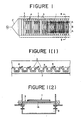
- FIGs 1 and 2 illustrating a conventional cooling system show a hot rolled wire rod 1 being laid on a cooling bed 7, by means of a laying cone, in the form of loops spaced at a predetermined pitch from one another in the longitudinal direction of the cooling bed,
- the loops are continuously transported in a predetermined, direction,i.e. to the right in Figures 1 and 2, by a conveying means, such as a roller conveyor 3, or chain conveyors 3' and rails 3", provided on the cooling bed 7.
- a conveying means such as a roller conveyor 3, or chain conveyors 3' and rails 3"
- the coiled wire rod is cooled by a cooling fluid, for example forced air projected from nozzles 4 provided in the cooling bed 7.
- the loops of the wire rod 1 overlap one another heavily or densely along their side portions i.e. densely overlapped portions A, and lightly or sparsely at their centre portion i.e. sparsely overlapped portion B. Accordingly, the cooling rate of the wire rod tends to vary between the densely overlapped portions A'and the sparsely overlapped portion B.
- the nozzles 4 are designed to direct the stream of the cooling fluid parallel to the plane of . the cooling bed 7, as indicated by an arrow X.
- the direction of the flow of the cooling fluid is parallel to the axis of the wire rod 1 at the densely overlapped portions A, and the cooling efficiency is accordingly poor at such portions.
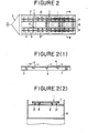
- the conveying means includes chain conveyors 3' and rails 3" extending in the direction of transportation
- so called low velocity zones will necessarily be formed immediately above the conveyors and the rails, as the direction of the cooling fluid is parallel to the plane of the cooling bed 7 and coincides with the direction of the transportation. Accordingly, uniform cooling of the entire wire rod cannot be attained because of the low velocity zones coupled with the variation in the overlapping density of the rod loops.
- hooks or fingers are in engagement with the coiled wire rod, and it is almost impossible to effect adequate cooling at such engaging portions. A variation in the cooling rate leads to a non-uniformity of the mechanical properties of the wire rod thereby obtained.
- a first embodiment of the present invention will npw be described with reference to Figures 3, 3(1), 3(2) and 3(3).
- Reference numeral 5 designates rollers of a roller conveyor for the transportation of a coiled wire rod.
- the coiled wire rod 1 sent from a laying cone in the form of loops spaced in a predetermined pitch from one another is transported in the direction indicated by an arrow C, in a manner similar to that described with reference to Figure 1.
- Numeral 6 designates nozzles for projecting a cooling fluid such as forced air.
- a number of upwardly directed nozzles 6 are arranged respectively between the adjacent rollers 5 and each nozzle extends in a transverse direction perpendicular to the transporting direction.
- the nozzle opening area ratio is 1.
- the angle of the nozzle face 6A of each nozzle is set to permit the projected fluid, i.e. the fluid from an air box 8 (see Figure 1(2)), to be directed at an angle of from 40° to 140° with respect to the plane of the cooling bed 7.
- the nozzle inner wall 6A is made flat so as to avoid the formation of a stream of cooling fluid in a direction parallel to the cooling bed 7.
- Figures 3(1), (2) and (3) show different cross sectional views taken along the line I-I of Figure 3.
- Figure 3(1) illustrates a vertically blowing type with an upward angle of 90°
- Figures 3(2) and (3) illustrate obliquely blowing types having an upward angle of 60° and 120° respectively.
- the locations of the openings of the nozzles, the number of the nozzles and the width of the openings of the nozzles at the densely overlapped portions A and at the sparsely overlapped portion B may be varied within a range of the nozzle opening area ratio from 0.8 to 1.2. Further, the cooling fluid may be projected in the same direction at the densely overlapped portions A and the sparsely overlapped portion B, or in different directions at such portions within an upward angle range of from 400 to 1 400 .
- the nozzles are designed to blow the cooling fluid upwardly at an angle of from 40 to 140 relative to the plane of the cooling bed so as to avoid the formation of a cooling fluid stream parallel to the cooling bed provided with rollers 5 of the roller conveyor, and at the same time to have aunozzle opening area ratio of from 0.8 to 1.2 at each position along the transverse;; direction of the cooling bed.
- the wire rod 1 is cooled by a parallel flow of the cooling fluid relative to the plane of the cooling bed, and accordingly, the stream of the cooling fluid is directed in the transporting direction of the coiled wire rod 1.
- the direction X of the fluid is parallel to the plane lA of the loops of the wire rod 1 as shown in Figures 1(1) and (2). Accordingly, the fluid impinges on the sparsely overlapped portion B of the coiled wire rod 1 atdan angle almost perpendicular to the axis of the wire rod 1, while it flowsparallel to the axis of the wire rod at the densely overlapped portion A.
- the parallel flow of the cooling fluid relative to the wire rod is disadvantageous from the standpoint of heat transfer since the cooling efficiency is then extremely poor. Besides, the cooling efficiency becomes locally poor particularly at such densely overlapped portions A, thus leading to the degradation of the tensile strength of the wire rod at the densely overlapped portions A.
- the cooling fluid is blown upwardly at an angle of from 40° to 140°, whereby the cooling fluid impinges on the wire rod at an angle substantially perpendicular thereto at any position along the transverse direction of the cooling bed.
- the cooling fluid is blown upwardly at an angle of from 40° to 140°, whereby the cooling fluid impinges on the wire rod at an angle substantially perpendicular thereto at any position along the transverse direction of the cooling bed.
- Figure 4 shows the tensile strength obtained at various levels of the upward angle i.e. the angle of the projection of the cooling fluid relative to the plane of the cooling bed. It will be seen that good tensile strength is obtainable within a range of the upward angle of from 40 0 to 140°. If the upward angle is less than 40 0 or more than 140°, the flow of the cooling fluid tends to be a parallel flow cooling mode and the flow distance from the cooling bed to the impinging point on the wire rod tends to be long, thus leading to a decrease in the flow velocity and giving rise to an overall decrease 6f the tensile strength.
- the upward angle is preferably from 60° to 120°.
- the cooling fluid is blown on to the coiled wire rod at an angle close to perpendicular to the plane of the loops, and the cooling efficiency at the densely overlapped portions A is thereby substantially improved, and it is unnecessary to supply a greater amount of forced air to the densely overlapped portions as was the case in the conventional system.
- the nozzles 6 so as to blow the same amount of cooling fluid against the coiled wire rod at each position in the transverse direction of the cooling bed, it is possible to cool the wire rod uniformly irrespective of the degree of the loop overlap.
- Figure 5 shows the average values and the variations of the tensile strength at various levels of the nozzle opening area ratio. It will be seen that the tensile strength variations are minimized within a range of the nozzle opening area ratio of from 0.8 to 1.2. If the nozzle opening area ratio is less than 0.8 or more than 1.2, the variation in the cooling rates at the densely overlapped portions and at the sparsely overlapped portion tends to be greater and consequently the variation in the tensile strength of the wire rod becomes greater.
- the nozzle opening area ratio is a ratio of summation of the nozzle opening area S 1 per unit transverse length of the nozzle opening at any particular position in the transverse direction-to the summation of the nozzle opening area So per unit transverse length of the nozzle opening at the centre position in the transverse direction. This ratio is thus represented by the following formula:
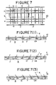
- Reference numeral 7' designates a cooling bed, and a plurality of cooling beds 7' are detachably mounted on an air box 9. Rails 10 are integrally formed on the cooling beds 7', and they are arranged linearly parallel to the transportation direction C in the illustrated embodiment.
- Reference numeral 11 designates chain conveyors which extend parallel to and inside of the respective rails 10 and sit on chain stands 12, as shown in Figure 8(2).
- the chain conveyors are provided with fingers 11A which hook the loops (not shown) of the coiled wire rod laid on the rails 10 for transporting the coiled wire in the transportation direction C.
- a number of nozzles are provided which respectively extend in a transverse direction and are adapted to blow out a cooling fluid substantially uniformly along the transverse direction, and which at the same time are spaced a predetermined distance from one another in the transporting direction C.
- the nozzles are designed to blow out the cooling fluid at an upward angle of from 40° to 140° with respect to the plane of the cooling bed, and the nozzle face 13A is flush with the upper surface of the cooling beds to avoid the formation of a cooling fluid stream parallel to the plane of the cooling beds.
- the nozzles 13 have a length covering the densely overlapped portions A and the sparsely overlapped portion B.
- the nozzles illustrated in Figure 7(1) are of a vertically blowing type with an upward angle of 90° while those illustrated in Figures 7(2) and (3) are of an obliquely blowing type with an upward angle of 60° and 120° respectively.
- the nozzle arrangement is simplified to permit the flowing rate of the cooling fluid to be constant.
- the portion corresponding to the sparsely overlapped portion B i.e. the cross-section along line II-II of Figure 7, may be the same as the portion corresponding to the densely overlapped portion A.
- the positions, the number and the opening width of the nozzles may be varied within a range where the nozzle opening areas are the same.
- the projecting directions of the cooling fluid at the densely overlapped portion A and the sparsely overlapped portion may be the same or different so long as they are within a range of the upward angle 9 of from 40 to 140°.
- Figure 8 illustrates a specific constructions wherein the same amount of cooling fluid impringes on the coiled wire rod at each position in the transverse direction of the cooling beds 7'.
- deflection nozzles 14 are provided at both sides of each chain conveyor 11, and at the same time a nozzle 15 is provided in the chain stand 12.
- the upward angle of these nozzles 14 and 15 are likewise set within a range of from 40° to 140°.
- the upward angle of the projected cooling fluid relative to the plane of the cooling bed is set within a range of from 40° to 140° thereby avoiding the formation of a parallel flow of the cooling fluid relative to the plane of the cooling bed, and at the same time, there are provided nozzles 14 and 15 immediately below ahd on both sides of the chain conveyors as well as the nozzles 13 extending transversely of the cooling bed.
- the nozzles 13,14 and 15 to blow out the cooling fluid at an upward angle 9 of from 40° to 140°, it is possible to permit the cooling fluid to impinge on the coiled wire rod at an angle substantially perpendicular thereto at any position in the transverse direction of the cooling bed, whereby the cooling can be done efficiently.
- good tensile strength is obtainable at an upward angle within a range of from 40° to 140°. If the upward angle is less than 40° or more than 140°, the cooling fluid tends to be in a parallel flow cooling mode and the flow distance from the surface of the cooling bed to the impinging point on the coiled wire rod tends to be long, thus leading to a decrease in the flow velocity and a decrease in the tensile strength.
- the cooling efficiency at the densely overlapped portions A is substantially improved and it is unnecessary to supply a greater amount of the cooling fluid at such portions A as was the case in the conventional system.
- the variation in the tensile strength can be minimized by setting the nozzle opening area ratio within a range of from 0.8 to 1.2 in the same manner as in the first embodiment. If the nozzle opening area ratio is less than 0.8 or greater than 1.2,the variation in the cooling rates at the densely overlapped portion A and the sparsely overlapped portion tends to increase, thus leading to an increase in the variation of the tensile strength.
- the nozzles 13,14 and 15 are arranged to permit the same amount of cooling fluid to impinge on the coiled wire rod at any position in the transverse direction of the cooling bed, whereby uniform cooling can be attained irrespective of the density of the loop overlap.
- the nozzles 15 and the deflection nozzles 14 are provided to attain uniform cooling at the low flow rate portions immediately above the chain conveyors.
- the variation in the tensile strength can be reduced.
Landscapes
- Chemical & Material Sciences (AREA)
- Engineering & Computer Science (AREA)
- Mechanical Engineering (AREA)
- Physics & Mathematics (AREA)
- Thermal Sciences (AREA)
- Crystallography & Structural Chemistry (AREA)
- Materials Engineering (AREA)
- Metallurgy (AREA)
- Organic Chemistry (AREA)
- Heat Treatment Of Strip Materials And Filament Materials (AREA)
Applications Claiming Priority (4)
| Application Number | Priority Date | Filing Date | Title |
|---|---|---|---|
| JP4122281A JPS57154308A (en) | 1981-03-18 | 1981-03-18 | Cooling device for hot rolling wire rod |
| JP4122181A JPS57154307A (en) | 1981-03-18 | 1981-03-18 | Cooling device for hot rolling wire rod |
| JP41221/81 | 1981-03-18 | ||
| JP41222/81 | 1981-03-18 |
Publications (2)
| Publication Number | Publication Date |
|---|---|
| EP0060732A2 true EP0060732A2 (de) | 1982-09-22 |
| EP0060732A3 EP0060732A3 (de) | 1983-03-23 |
Family
ID=26380784
Family Applications (1)
| Application Number | Title | Priority Date | Filing Date |
|---|---|---|---|
| EP82301398A Withdrawn EP0060732A3 (de) | 1981-03-18 | 1982-03-18 | Steuerbare Kühleinrichtung für Walzdraht |
Country Status (3)
| Country | Link |
|---|---|
| US (1) | US4423856A (de) |
| EP (1) | EP0060732A3 (de) |
| CA (1) | CA1172446A (de) |
Cited By (2)
| Publication number | Priority date | Publication date | Assignee | Title |
|---|---|---|---|---|
| EP0110652A1 (de) * | 1982-11-22 | 1984-06-13 | MORGAN CONSTRUCTION COMPANY (a Massachusetts corporation) | Anlage und Verfahren zum Walzen und Behandeln von Stahldraht |
| EP0746632A4 (de) * | 1991-11-07 | 1996-08-27 | Charles H Gage | Vorrichtung zur kühlung von stahlbarren |
Families Citing this family (16)
| Publication number | Priority date | Publication date | Assignee | Title |
|---|---|---|---|---|
| BR8504750A (pt) * | 1984-11-14 | 1986-07-22 | Nippon Steel Corp | Aparelho de revestimento de tira para um forno de recozimento continuo |
| US4945746A (en) * | 1988-12-27 | 1990-08-07 | National Steel Corporation | Containment fence for runout table |
| NL9001462A (nl) * | 1990-06-27 | 1992-01-16 | Hoogovens Groep Bv | Koelsysteem voor het koelen van een bewegende metaalband. |
| US5299783A (en) * | 1991-04-30 | 1994-04-05 | Engineered Production Increase, Inc. | Rod cooling apparatus |
| US5871596A (en) * | 1997-04-08 | 1999-02-16 | Morgan Construction Company | Apparatus and method for cooling hot rolled steel rod |
| WO2004014577A1 (ja) * | 2002-08-08 | 2004-02-19 | Jfe Steel Corporation | 熱延鋼帯の冷却装置、熱延鋼帯の製造方法および熱延鋼帯の製造ライン |
| GB2438267A (en) * | 2006-05-19 | 2007-11-21 | Corus Uk Ltd | Apparatus for cooling of coiled steel rod |
| US8900300B1 (en) | 2012-02-22 | 2014-12-02 | Omega Ophthalmics Llc | Prosthetic capsular bag and method of inserting the same |
| AU2015277207B2 (en) | 2014-06-19 | 2018-03-29 | Omega Ophthalmics Llc | Prosthetic capsular devices, systems, and methods |
| US9358103B1 (en) | 2015-02-10 | 2016-06-07 | Omega Ophthalmics Llc | Prosthetic capsular devices, systems, and methods |
| US9993336B2 (en) | 2016-06-06 | 2018-06-12 | Omega Ophthalmics Llc | Prosthetic capsular devices, systems, and methods |
| WO2018075932A1 (en) | 2016-10-21 | 2018-04-26 | Omega Ophthalmics Llc | Prosthetic capsular devices, systems, and methods |
| AU2019249216B2 (en) | 2018-04-06 | 2024-07-18 | Omega Ophthalmics Llc | Prosthetic capsular devices, systems, and methods |
| CN112139239B (zh) * | 2020-08-11 | 2023-04-14 | 柳州钢铁股份有限公司 | 性能线差小的切分钢筋 |
| CN112139240B (zh) * | 2020-08-11 | 2023-04-07 | 柳州钢铁股份有限公司 | 缩小钢筋性能线差的生产方法 |
| WO2022082170A1 (en) | 2020-10-12 | 2022-04-21 | Omega Ophthalmics Llc | Prosthetic capsular devices, systems, and methods |
Family Cites Families (5)
| Publication number | Priority date | Publication date | Assignee | Title |
|---|---|---|---|---|
| GB1024713A (en) * | 1962-08-24 | 1966-04-06 | Morgan Construction Co | Apparatus and process for the controlled cooling of rods |
| US3940961A (en) | 1974-11-18 | 1976-03-02 | Morgan Construction Company | Apparatus for cooling hot rolled steel rod by forced air convection or by supplying heat |
| US3940967A (en) | 1975-01-10 | 1976-03-02 | Morgan Construction Company | Apparatus for controlled cooling hot rolled steel rod in direct sequence with rod mill |
| DE2601492C3 (de) * | 1975-01-18 | 1979-10-04 | Kobe Steel, Ltd., Kobe, Hyogo (Japan) | Vorrichtung zum Kühlen eines Drahtes unmittelbar nach dem Warmwalzen |
| JPS5183043A (en) | 1975-01-18 | 1976-07-21 | Kobe Steel Ltd | Netsukanatsuensenzaino reikyakuhoho narabini sonosochi |
-
1982
- 1982-03-18 EP EP82301398A patent/EP0060732A3/de not_active Withdrawn
- 1982-03-18 CA CA000398707A patent/CA1172446A/en not_active Expired
- 1982-03-18 US US06/359,231 patent/US4423856A/en not_active Expired - Lifetime
Cited By (2)
| Publication number | Priority date | Publication date | Assignee | Title |
|---|---|---|---|---|
| EP0110652A1 (de) * | 1982-11-22 | 1984-06-13 | MORGAN CONSTRUCTION COMPANY (a Massachusetts corporation) | Anlage und Verfahren zum Walzen und Behandeln von Stahldraht |
| EP0746632A4 (de) * | 1991-11-07 | 1996-08-27 | Charles H Gage | Vorrichtung zur kühlung von stahlbarren |
Also Published As
| Publication number | Publication date |
|---|---|
| EP0060732A3 (de) | 1983-03-23 |
| US4423856A (en) | 1984-01-03 |
| CA1172446A (en) | 1984-08-14 |
Similar Documents
| Publication | Publication Date | Title |
|---|---|---|
| EP0060732A2 (de) | Steuerbare Kühleinrichtung für Walzdraht | |
| EP0691929B1 (de) | Pneumatischer stauförderer mit doppelter luftkammer | |
| US4298341A (en) | Industrial oven having air recirculating means for minimizing heat loss | |
| KR100580357B1 (ko) | 강판의 냉각 방법 및 그 장치 | |
| EP0464890B1 (de) | Kühlsystem zum Kühlen eines bewegten Metallbandes | |
| JPS6314053B2 (de) | ||
| JP4620327B2 (ja) | 流体を薄い要素の少なくとも表面に吹きつける装置及び組合された吹きつけユニット | |
| EP0181101B1 (de) | Vorrichtung und Verfahren zum Abkühlen durch Luft eines warmgewalzten Rundstahlmaterials | |
| EP0646089B1 (de) | Tunnelschiene-pneumatisches rohrsystem | |
| US4983201A (en) | Method and apparatus in a glass sheet bending furnace for preventing the deflection of mould wagon bearing rails | |
| JP3525941B2 (ja) | 曲げ板ガラスの製造装置 | |
| RU2179588C2 (ru) | Устройство и способ охлаждения горячекатаного стального прутка | |
| US20060150683A1 (en) | Apparatus and method for glass sheet quenching | |
| JP2000297331A (ja) | ガスジェット冷却装置 | |
| US4106757A (en) | Hover furnaces | |
| JP2005041594A (ja) | 浮上式ベルトコンベヤ装置 | |
| JPH02112816A (ja) | 熱間圧延線材の空冷装置 | |
| JPS63223120A (ja) | 冷却装置 | |
| US5471764A (en) | Can end drying oven | |
| JPH10287438A (ja) | ガラス板の冷却装置 | |
| JPH10192951A (ja) | 高温鋼板の冷却方法および装置 | |
| US3445100A (en) | Fluidized bed apparatus for quenching hot rod | |
| KR20000073731A (ko) | 선재제조설비의 선재냉각장치 | |
| JP3076430B2 (ja) | H形鋼フランジ水冷装置 | |
| JPS61193717A (ja) | 鋼板の均一冷却方法 |
Legal Events
| Date | Code | Title | Description |
|---|---|---|---|
| PUAI | Public reference made under article 153(3) epc to a published international application that has entered the european phase |
Free format text: ORIGINAL CODE: 0009012 |
|
| 17P | Request for examination filed |
Effective date: 19820408 |
|
| AK | Designated contracting states |
Designated state(s): BE DE FR GB |
|
| PUAL | Search report despatched |
Free format text: ORIGINAL CODE: 0009013 |
|
| AK | Designated contracting states |
Designated state(s): BE DE FR GB |
|
| STAA | Information on the status of an ep patent application or granted ep patent |
Free format text: STATUS: THE APPLICATION IS DEEMED TO BE WITHDRAWN |
|
| 18D | Application deemed to be withdrawn |
Effective date: 19861023 |
|
| RIN1 | Information on inventor provided before grant (corrected) |
Inventor name: NISHIYAMA, TOSHIKAZU Inventor name: NISHIWAKI, TAKASHI Inventor name: ICHIDA, YUTAKA Inventor name: TAKAHASHI, EIJI Inventor name: SHIMAZU, SHINICHI Inventor name: WADA, YUKIO Inventor name: IWAMI, ICHIRO |