EP0110787A2 - Verfahren und Gerät zur Formung von Schnittbildern eines Körpers - Google Patents
Verfahren und Gerät zur Formung von Schnittbildern eines Körpers Download PDFInfo
- Publication number
- EP0110787A2 EP0110787A2 EP83402283A EP83402283A EP0110787A2 EP 0110787 A2 EP0110787 A2 EP 0110787A2 EP 83402283 A EP83402283 A EP 83402283A EP 83402283 A EP83402283 A EP 83402283A EP 0110787 A2 EP0110787 A2 EP 0110787A2
- Authority
- EP
- European Patent Office
- Prior art keywords
- frames
- series
- filtering
- detector
- rotation
- Prior art date
- Legal status (The legal status is an assumption and is not a legal conclusion. Google has not performed a legal analysis and makes no representation as to the accuracy of the status listed.)
- Granted
Links
Images


Classifications
-
- A—HUMAN NECESSITIES
- A61—MEDICAL OR VETERINARY SCIENCE; HYGIENE
- A61B—DIAGNOSIS; SURGERY; IDENTIFICATION
- A61B6/00—Apparatus or devices for radiation diagnosis; Apparatus or devices for radiation diagnosis combined with radiation therapy equipment
- A61B6/48—Diagnostic techniques
- A61B6/481—Diagnostic techniques involving the use of contrast agents
-
- A—HUMAN NECESSITIES
- A61—MEDICAL OR VETERINARY SCIENCE; HYGIENE
- A61B—DIAGNOSIS; SURGERY; IDENTIFICATION
- A61B6/00—Apparatus or devices for radiation diagnosis; Apparatus or devices for radiation diagnosis combined with radiation therapy equipment
- A61B6/02—Arrangements for diagnosis sequentially in different planes; Stereoscopic radiation diagnosis
- A61B6/027—Arrangements for diagnosis sequentially in different planes; Stereoscopic radiation diagnosis characterised by the use of a particular data acquisition trajectory, e.g. helical or spiral
-
- A—HUMAN NECESSITIES
- A61—MEDICAL OR VETERINARY SCIENCE; HYGIENE
- A61B—DIAGNOSIS; SURGERY; IDENTIFICATION
- A61B6/00—Apparatus or devices for radiation diagnosis; Apparatus or devices for radiation diagnosis combined with radiation therapy equipment
- A61B6/50—Apparatus or devices for radiation diagnosis; Apparatus or devices for radiation diagnosis combined with radiation therapy equipment specially adapted for specific body parts; specially adapted for specific clinical applications
- A61B6/504—Apparatus or devices for radiation diagnosis; Apparatus or devices for radiation diagnosis combined with radiation therapy equipment specially adapted for specific body parts; specially adapted for specific clinical applications for diagnosis of blood vessels, e.g. by angiography
-
- G—PHYSICS
- G06—COMPUTING OR CALCULATING; COUNTING
- G06T—IMAGE DATA PROCESSING OR GENERATION, IN GENERAL
- G06T12/00—Tomographic reconstruction from projections
- G06T12/10—Image preprocessing, e.g. calibration, positioning of sources or scatter correction
Definitions
- the present invention relates to a method of forming images of the internal structure of a body and more particularly relates to a method and an apparatus for obtaining images in sections of a body.
- the objective is conventionally to obtain an image of one or more sections or planes of the internal structure of a body by combining information from a certain number of images obtained from different perspectives. angular in order to obtain a single processed image for each section. Typically, multiple images are processed and added by a computer or photographically to ultimately obtain a single processed image. The process can then be repeated for other cuts or shots inside the body.
- X-ray contrast agents are used to create a large difference in X-ray absorption behavior. Blood vessels are virtually invisible on X-ray images (except in the chest) because of blood, muscle, fat, and soft tissue all have similar X-ray absorption behavior. X-ray contrast agents contain a product with X-ray absorption properties that are different from those of blood, muscle, fat and soft tissue.
- the vascular structure artificially produces a stronger contrast on an X-ray image while the contrast agent is located within a certain vascular segment.
- the present invention relates to a method and apparatus for producing a processed image of a section of a body.
- a tomography is carried out in which a series of video frames of a section of a body can be observed in real time.
- a recorded series of frames of a main plane of a body being examined can be processed to obtain a corresponding series of frames which represent an interesting plane which is spaced from the main plane, thus avoiding the obligation to carry out a re-exposure for each new plan to be observed.
- a body is disposed between an assembly formed by a radiation source and an associated detector, so that a beam of radiation emitted by the source arrives angularly on the body and passes through it in the direction of the detector.
- a relative rotational movement is established between the beam and the body (for example by moving the source-detector assembly, the body or both) so that an interesting main plane of the body remains essentially in focus during the movement relative rotation.
- a series of frames of electronic video signals is obtained from the detector, for different angular positions, the frames representing the images of the radiation transmission characteristics of the body at a series of successive instants. The frames of the series are filtered temporally and then displayed.
- the time filtering step consists in filtering the series of video signal frames from a filtering function having a time frequency response which corresponds substantially to the time frequency of the movement. of a "bolus" of a contrast material in the region being observed.
- this temporal response becomes very small at an instant which is less than the rotation time characteristic of the tomography system.
- the temporal filter acts in such a way as to filter out the tomographic movement, as well as certain other types of movement and, if desired, a stationary anatomy.
- each frame of the series of frames obtained comprises a group of elementary image elements called pixels, the level of video signal for each pixel being determined by the transmissivity of radiation of an elementary region of the main plane and adjacent planes through which the rays of the beam pass.
- geometric transformations are carried out to shift the levels of the video signal in different pixel positions, the transformations being dark. tion of the relative angle of rotation associated with the frame containing the pixel, and of the distance between the plane of interest to be represented and the main plane.
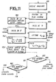
- FIG. 1 there is shown a block diagram of an embodiment of an apparatus 100 for obtaining sectional images of the internal structure of a body 20.
- the apparatus 100 comprises a conventional circular tomography mechanism or elliptical 15, modified for radioscopic application.
- a radiation source 110 typically an X-ray source
- a detector 120 are mounted so as to rotate in a coordinated manner, for example around an axis of the body 20, under the control of a tomographic drive 18.
- the tomography mechanism can be of the type manufactured by CGR Médical Corp. of Baltimore Maryland.
- a video generator 130 operates in combination with the detector 120.
- the combination of the detector and the video generator may include, for example, an x-ray image intensifier in cooperation with a television camera.
- the output of the video generator 130 is connected to a video recorder 150 and also to an analog-digital converter 151, which converts the television signal into a digital form and which generates sequential addresses.
- the output of the recorder 150 is also connected to the converter 151.
- Equipment making it possible to obtain the digitally converted television siganl is well known in the prior art and commercially available, an example being constituted by the model AD-964310 manufactured by THOMSON-CSF Broadcast, Inc.
- the digital television signal converter For each pixel in the video frame, the digital television signal converter generates a digital signal, for example an eight-bit digital signal, representing one of the 256 luminance level gradations (for a monochrome signal - as considered in the embodiment shown), together with an address which defines the position of the pixel.
- the video recorder 150 may be any suitable recording device, such as a tape or disc video recorder.
- the video generator, video recorder and analog-to-digital converter conventionally receive synchronization signals and the analog-to-digital converter also receives clock signals at the pixel frequency.
- the output of the analog-digital converter 151 is applied to an offset circuit x, y 200, which can include a processor such as a digital computer or a microprocessor.
- the processor 200 may include a model 68000 microprocessor made by Motorola Corp., or an embodiment thereof called a "bit slice".
- the processor which can be programmed in accordance with the program described with reference to FIG. 11, ensures an offset of the address of a current pixel, the offset address of the pixel being applied to the recurrent filtering system 300.
- the level signal signal for the current pixel is also applied to the recurrent filtering subsystem 300, which is described with reference to Figure 12.
- the output signal from the recurrent filtering system 300 is applied to a digital-to-analog converter 195 whose output signal is applied to a display device 198 and a video recorder 199. Again, it has been assumed that synchronization signals and clock signals are conventionally available in these circuits.
- FIG. 2 shows the geometry and the position of two points in a three-dimensional object to be represented in image, a point being located in the main plane (or focal plane) and a second point being located in a plane placed above. (Since the input surface of the image intensifier is not planar, focal planes are actually two-dimensional curved surfaces, similar in shape to the input surface of the image intensifier element. Since the curvature is small, this distortion is not considered to have a great consequence). We will assume for the moment that the object is stationary.
- the projection of the focal point always falls on the same pixel (the same point on the surface of the image intensifying element).
- the projection of the point in the plane above it draws a circle on the surface of the image intensifier element.
- An isolated pixel placed along the path of this point on the image intensifier element surface "sees" this point once per second.
- the temporal variations of image associated with these two points are indicated respectively in FIGS. 3 and 4.
- the focal point involves only a component of direct current at a zero time frequency.
- the non-focal point involves a DC component, and also peaks at + 1 cycle / s, and also harmonics greater than + n cycle / s, where n is an integer.
- time frequency components can be eliminated from non-focal planes, while a stationary background anatomy from all planes is simultaneously eliminated, by passing the video signals coming from the tomographic sequence through a recurrent filtering system, such as the filtering system represented in FIG. 12 and described in the American patent application No. 342 376.
- the filter response for a zero time frequency is close to zero, and above 1 Hz it is very small.
- the combined effect of rapid periodic movement and bandwidth filtering is to remove most non-arterial structures and visualize arteries in an area of the focal plane with good resolution, and also to form images of arteries located in other distant planes, in the form of blurred arteries, the blur increasing with the distance from the focal plane.
- Other time filters can be used.
- the focal plane can be changed by moving the patient or by stepping movement of the tomography mechanism.
- a limitation to the image formation process described is that, although it can be performed in real time, an image is only obtained from one plane. However, as indicated above, if the original sequence of images is stored, this sequence can be used so as to synthesize other shots without re-exposure of the patient.
- point projections located in non-focal planes trace circular paths in the detector plane.
- the angular positions associated with each digitally converted video frame it is possible to determine the image offsets (angles and radii) associated with a given plane for a specified angular position.
- FIG. 11 is a flow diagram of the control program of the processor 200 (FIG. 1) for ensuring the offset of the addresses of pixels for the observation of a plane of interest other than the main plane.
- the angular velocity of the tomographic system is introduced (block 1110) and the position of the plane of interest, that is to say the distance and its direction from the main plane, is also entered (block 1115).
- the angular difference between the frames is then obtained by program from the angular speed introduced and the number of frames per second to be used, this function being represented by block 1120.
- the base radius, R is then determined according to the considered plane and tomographic angle (block 1125).
- the characteristic angle ⁇ is then calculated for the next frame, by adding the angular difference between frames to the accumulation of angles (block 1130).
- the pixel pre-offset address x 0 is read there (block 1135).
- the relations (1) and (2) are then used to calculate the offset components ⁇ x and ⁇ y, as represented by block 1140.
- the offset address of pixel x + ⁇ x, and yo + ⁇ y, is then calculated, as represents by block 1145.
- the offset pixel address is then transmitted to filtering system (block 1150) and a determination is made to define whether or not the pixel whose address had just been processed was the last visible pixel of a frame (diamond 1155). If not, the next pixel is expected and then we enter block 1135 again.
- FIG 12 there is shown a block diagram of a time filter system 300 which, in the present embodiment, is of the type described in the US patent application No. 342 376 mentioned above.
- the temporal filtering system comprises a first recurring filtering subsystem 200 and a second recurring filtering subsystem 300.
- the subsystem 200 includes an addition circuit 210 which receives, at an input, the signal which is produced by the analog-digital converter 151 and which is designated by x (t) and it receives at its other input a signal designated by y (tT), to be described below, where T designates the period of video frames.
- the input of the addition circuit 210 which receives the signal x (t) is weighted by a weighting factor k l
- the input of the addition circuit 210 which receives the signal y (tT) is weighted by a factor weighting (1-k l ).
- the output signal of the addition circuit 210 is a signal designated by y (t), and this signal is applied to a digital frame memory 220.
- the digital frame memory can for example comprise a digital video frame memory model FS -963155 manufactured by THOMSON-CSF Broadcast, Inc.
- any suitable memory such as a random access memory, comprising pixel addresses (if they are not offset) which are supplied by the address generation part of block 151 with generation of synchronization and clock signals.
- offset addresses are used in other observation plans than the main plane, they are introduced from processor 200, as described above.
- the output signal from the digital frame memory 200 is constituted in this embodiment by the signal designated by y (t), that is to say the output signal from the addition circuit 210.
- the second recurrent filtering subsystem 300 comprises an addition circuit 310 which receives at an input the signal which is supplied by the analog-digital signal 151 and which is designated by x (t), and which receives at its other input a signal designated by z (tT), to be described below.
- the input of the addition circuit 310 which receives the signal x (t) is weighted by a weighting factor k 2 and the input of the addition circuit 310 which receives the signal z (tT) is weighted by a factor of weighting (1-k 2 ).
- the output signal of the addition circuit 310 is a signal designated by z (t) and this signal is applied to a digital frame memory 320 which can be of the same type as the digital frame memory 220 and which operates in a similar way.
- the output signal y (t) of the subsystem 200 and the output signal z (t) of the subsystem 300 are applied to a difference circuit 410 where the difference y (t) - z (t) is obtained.
- This difference signal is applied to a digital analog converter 195 (FIG. 1) for display and / or recording.
- k and k 2 so as to establish a desired temporal characteristic.
- the response below 0.003 Hz is essentially zero and it is very small above 1 Hz.
- the present invention can be used in cooperation with techniques which further process the series of frames generated as described above; for example by the type of processing which records a follow-up of the maximum clouding of each pixel (as described in American patent application No. 333,558) and / or which keeps track of the time necessary until maximum clouding (as described in American patent application No. 444,614).
- the recurrent filtering system 300 can be arranged in cascade using two of the filters described in series or by passing the signals twice through the same filtering system. This serves, among other things, to establish an overall filtering characteristic that is much less sensitive to the component of tomographic movement.
Landscapes
- Health & Medical Sciences (AREA)
- Life Sciences & Earth Sciences (AREA)
- Engineering & Computer Science (AREA)
- Medical Informatics (AREA)
- Physics & Mathematics (AREA)
- Radiology & Medical Imaging (AREA)
- Surgery (AREA)
- High Energy & Nuclear Physics (AREA)
- Veterinary Medicine (AREA)
- Nuclear Medicine, Radiotherapy & Molecular Imaging (AREA)
- Optics & Photonics (AREA)
- Pathology (AREA)
- Public Health (AREA)
- Biomedical Technology (AREA)
- Heart & Thoracic Surgery (AREA)
- Molecular Biology (AREA)
- Biophysics (AREA)
- Animal Behavior & Ethology (AREA)
- General Health & Medical Sciences (AREA)
- General Physics & Mathematics (AREA)
- Theoretical Computer Science (AREA)
- Vascular Medicine (AREA)
- Dentistry (AREA)
- Oral & Maxillofacial Surgery (AREA)
- Image Processing (AREA)
- Image Analysis (AREA)
- Apparatus For Radiation Diagnosis (AREA)
Applications Claiming Priority (2)
| Application Number | Priority Date | Filing Date | Title |
|---|---|---|---|
| US444613 | 1982-11-26 | ||
| US06/444,613 US4577222A (en) | 1982-11-26 | 1982-11-26 | Apparatus and method for cross sectional imaging of a body |
Publications (3)
| Publication Number | Publication Date |
|---|---|
| EP0110787A2 true EP0110787A2 (de) | 1984-06-13 |
| EP0110787A3 EP0110787A3 (en) | 1986-02-05 |
| EP0110787B1 EP0110787B1 (de) | 1989-03-15 |
Family
ID=23765624
Family Applications (1)
| Application Number | Title | Priority Date | Filing Date |
|---|---|---|---|
| EP83402283A Expired EP0110787B1 (de) | 1982-11-26 | 1983-11-25 | Verfahren und Gerät zur Formung von Schnittbildern eines Körpers |
Country Status (3)
| Country | Link |
|---|---|
| US (1) | US4577222A (de) |
| EP (1) | EP0110787B1 (de) |
| DE (1) | DE3379432D1 (de) |
Cited By (1)
| Publication number | Priority date | Publication date | Assignee | Title |
|---|---|---|---|---|
| EP0377267A3 (de) * | 1989-01-05 | 1992-01-22 | The Regents Of The University Of California | 3D Bildrekonstruktionsverfahren und -gerät zur Plazierung von 3D Strukturen auf einer gemeinsamen schiefen oder eingegrenzten Volumenscheibe ohne Volumenauflösungsverlust |
Families Citing this family (14)
| Publication number | Priority date | Publication date | Assignee | Title |
|---|---|---|---|---|
| FR2604048B1 (fr) * | 1986-09-12 | 1989-06-09 | Thomson Cgr | Installation de radiologie a camera de television a element de prise de vues de faible remanence |
| US5099859A (en) * | 1988-12-06 | 1992-03-31 | Bell Gene D | Method and apparatus for comparative analysis of videofluoroscopic joint motion |
| US5210688A (en) * | 1990-05-21 | 1993-05-11 | General Motors Corporation | Sinography method and apparatus |
| GB2271685B (en) * | 1992-10-13 | 1996-06-12 | Grass Valley Group | Swept illumination method and apparatus for three-dimensional volume visualization |
| US5280357A (en) * | 1992-10-13 | 1994-01-18 | The Grass Valley Group, Inc. | Depth-based recursive video effects |
| US6507631B1 (en) * | 1999-12-22 | 2003-01-14 | Tetsuo Takuno | X-ray three-dimensional imaging method and apparatus |
| US6914958B2 (en) * | 2001-07-06 | 2005-07-05 | Ge Medical Systems Global Technology Company, Llc | Multi-plane acquisition in digital x-ray radiography |
| FR2847798B1 (fr) * | 2002-11-28 | 2006-02-10 | Ge Med Sys Global Tech Co Llc | Procede pour determiner des parametres fonctionnels dans un dispositif de fluoroscopie |
| FR2847797B1 (fr) | 2002-11-28 | 2005-09-23 | Ge Med Sys Global Tech Co Llc | Perfectionnements aux procedes et dispositifs d'imagerie fluoroscopique |
| JP2005064706A (ja) * | 2003-08-08 | 2005-03-10 | Shimadzu Corp | 放射線撮像装置および放射線検出信号処理方法 |
| EP1658009B1 (de) * | 2003-08-20 | 2011-10-12 | Philips Intellectual Property & Standards GmbH | Verfahren und vorrichtung für die flussrekonstruktion |
| JP5675370B2 (ja) * | 2008-03-06 | 2015-02-25 | コーニンクレッカ フィリップス エヌ ヴェ | 管系を解析する方法 |
| US9247920B2 (en) | 2014-02-27 | 2016-02-02 | General Electric Company | System and method for performing bi-plane tomographic acquisitions |
| JP6482934B2 (ja) | 2014-06-03 | 2019-03-13 | キヤノンメディカルシステムズ株式会社 | 画像処理装置、放射線検出装置および画像処理方法 |
Family Cites Families (4)
| Publication number | Priority date | Publication date | Assignee | Title |
|---|---|---|---|---|
| US3976885A (en) * | 1975-03-18 | 1976-08-24 | Picker Corporation | Tomography system having nonconcurrent, compound axial scanning |
| GB1571509A (en) * | 1976-03-03 | 1980-07-16 | Emi Ltd | Radiography |
| US4291333A (en) * | 1979-05-22 | 1981-09-22 | Fernseh Inc. | Noise filter |
| US4437161A (en) * | 1981-06-29 | 1984-03-13 | Siemens Gammasonics Inc. | Medical imaging apparatus |
-
1982
- 1982-11-26 US US06/444,613 patent/US4577222A/en not_active Expired - Lifetime
-
1983
- 1983-11-25 DE DE8383402283T patent/DE3379432D1/de not_active Expired
- 1983-11-25 EP EP83402283A patent/EP0110787B1/de not_active Expired
Non-Patent Citations (1)
| Title |
|---|
| MEDICAL PHYSICS, vol. 5, no. 6, novembre/décembre 1978, pages 485-490, Am. Assoc. Phys. Med., New York, US; J.E. HOLDEN et al.: "Continuous time-dependence in computed tomography" * |
Cited By (1)
| Publication number | Priority date | Publication date | Assignee | Title |
|---|---|---|---|---|
| EP0377267A3 (de) * | 1989-01-05 | 1992-01-22 | The Regents Of The University Of California | 3D Bildrekonstruktionsverfahren und -gerät zur Plazierung von 3D Strukturen auf einer gemeinsamen schiefen oder eingegrenzten Volumenscheibe ohne Volumenauflösungsverlust |
Also Published As
| Publication number | Publication date |
|---|---|
| EP0110787B1 (de) | 1989-03-15 |
| US4577222A (en) | 1986-03-18 |
| EP0110787A3 (en) | 1986-02-05 |
| DE3379432D1 (en) | 1989-04-20 |
Similar Documents
| Publication | Publication Date | Title |
|---|---|---|
| EP0113605B1 (de) | Verfahren und Einrichtung zur Erzeugung eines Körperröntgenbildes | |
| EP0110787B1 (de) | Verfahren und Gerät zur Formung von Schnittbildern eines Körpers | |
| KR101077051B1 (ko) | 치과용 구강외 엑스레이 영상 시스템 | |
| FR2864301A1 (fr) | Systeme et procede de tomosynthese radioscopique | |
| EP0459853B1 (de) | Verfahren zur Erfassung von Echographie-Bildern | |
| DE69935193T2 (de) | Tomografisches Verfahren und System | |
| US20170367586A9 (en) | Photoacoustic computed tomography with an acoustic reflector | |
| FR2870710A1 (fr) | Procede et dispositif pour mesurer des structures anatomiques | |
| FR2799028A1 (fr) | Procede de reconstitution d'une image tridimentionnelle d'elements de fort contraste | |
| US5413105A (en) | Median temporal filtering of ultrasonic data | |
| FR2812741A1 (fr) | Procede et dispositif de reconstruction d'une image tridimensionnelle dynamique d'un objet parcouru par un produit de contraste | |
| JPS59111740A (ja) | X線ハイブリツド減算用整合フイルタ | |
| FR2593698A1 (fr) | Appareil d'examen de milieux en mouvement par echographie ultrasonore | |
| JPH031869B2 (de) | ||
| JPH11151224A (ja) | 血管造影図の撮影装置 | |
| CN109803588A (zh) | 流体路径的增强分辨率超声成像 | |
| FR2736181A1 (fr) | Procede de traitement d'images pour la reduction du bruit dans une image d'une sequence d'images numeriques et dispositif mettant en oeuvre ce procede | |
| EP0101336B1 (de) | Generator zur Verarbeitung eines Videosignals mit Kontrast für Strahlenkunde und Verfahren für derartige Signalverarbeitung | |
| FR2994525A1 (fr) | Systeme et procede d'imagerie echographique | |
| JPS63290547A (ja) | テレビ断層撮影装置 | |
| FR2884341A1 (fr) | Procede et systeme d'amelioration d'une image digitale generee a partir d'un detecteur de rayons x | |
| JP2008515522A (ja) | 高画質x線投影像の生成のための画像化システム | |
| FR2799029A1 (fr) | Procede de reconstruction d'une image tridimensionnelle d'un objet en mouvement, en particulier une image tridimensionnelle de vaisseaux du coeur humain | |
| FR2799030A1 (fr) | Procede de reconstruction d'une image tridimensionnelle d'un element d'interet, par exemple un elargisseur vasculaire insere dans un vaisseau | |
| FR2880234A1 (fr) | Procede et systeme de correction de dispersion pendant une imagerie en deux plans avec exposition simultanee |
Legal Events
| Date | Code | Title | Description |
|---|---|---|---|
| PUAI | Public reference made under article 153(3) epc to a published international application that has entered the european phase |
Free format text: ORIGINAL CODE: 0009012 |
|
| AK | Designated contracting states |
Designated state(s): DE FR GB IT NL |
|
| PUAL | Search report despatched |
Free format text: ORIGINAL CODE: 0009013 |
|
| AK | Designated contracting states |
Designated state(s): DE FR GB IT NL |
|
| 17P | Request for examination filed |
Effective date: 19860224 |
|
| 17Q | First examination report despatched |
Effective date: 19880804 |
|
| RAP1 | Party data changed (applicant data changed or rights of an application transferred) |
Owner name: GENERAL ELECTRIC CGR SA. |
|
| GRAA | (expected) grant |
Free format text: ORIGINAL CODE: 0009210 |
|
| AK | Designated contracting states |
Kind code of ref document: B1 Designated state(s): DE FR GB IT NL |
|
| PG25 | Lapsed in a contracting state [announced via postgrant information from national office to epo] |
Ref country code: IT Free format text: LAPSE BECAUSE OF FAILURE TO SUBMIT A TRANSLATION OF THE DESCRIPTION OR TO PAY THE FEE WITHIN THE PRESCRIBED TIME-LIMIT;WARNING: LAPSES OF ITALIAN PATENTS WITH EFFECTIVE DATE BEFORE 2007 MAY HAVE OCCURRED AT ANY TIME BEFORE 2007. THE CORRECT EFFECTIVE DATE MAY BE DIFFERENT FROM THE ONE RECORDED. Effective date: 19890315 |
|
| GBT | Gb: translation of ep patent filed (gb section 77(6)(a)/1977) | ||
| REF | Corresponds to: |
Ref document number: 3379432 Country of ref document: DE Date of ref document: 19890420 |
|
| PGFP | Annual fee paid to national office [announced via postgrant information from national office to epo] |
Ref country code: GB Payment date: 19891031 Year of fee payment: 7 |
|
| PLBE | No opposition filed within time limit |
Free format text: ORIGINAL CODE: 0009261 |
|
| STAA | Information on the status of an ep patent application or granted ep patent |
Free format text: STATUS: NO OPPOSITION FILED WITHIN TIME LIMIT |
|
| 26N | No opposition filed | ||
| PG25 | Lapsed in a contracting state [announced via postgrant information from national office to epo] |
Ref country code: GB Effective date: 19901125 |
|
| GBPC | Gb: european patent ceased through non-payment of renewal fee | ||
| PGFP | Annual fee paid to national office [announced via postgrant information from national office to epo] |
Ref country code: NL Payment date: 19921130 Year of fee payment: 10 |
|
| PG25 | Lapsed in a contracting state [announced via postgrant information from national office to epo] |
Ref country code: NL Effective date: 19940601 |
|
| NLV4 | Nl: lapsed or anulled due to non-payment of the annual fee | ||
| PGFP | Annual fee paid to national office [announced via postgrant information from national office to epo] |
Ref country code: FR Payment date: 20021030 Year of fee payment: 20 |
|
| PGFP | Annual fee paid to national office [announced via postgrant information from national office to epo] |
Ref country code: DE Payment date: 20021202 Year of fee payment: 20 |