EP0459853B1 - Verfahren zur Erfassung von Echographie-Bildern - Google Patents
Verfahren zur Erfassung von Echographie-Bildern Download PDFInfo
- Publication number
- EP0459853B1 EP0459853B1 EP91401237A EP91401237A EP0459853B1 EP 0459853 B1 EP0459853 B1 EP 0459853B1 EP 91401237 A EP91401237 A EP 91401237A EP 91401237 A EP91401237 A EP 91401237A EP 0459853 B1 EP0459853 B1 EP 0459853B1
- Authority
- EP
- European Patent Office
- Prior art keywords
- image
- images
- probe
- real time
- practitioner
- Prior art date
- Legal status (The legal status is an assumption and is not a legal conclusion. Google has not performed a legal analysis and makes no representation as to the accuracy of the status listed.)
- Expired - Lifetime
Links
- 238000000034 method Methods 0.000 title claims description 26
- 239000000523 sample Substances 0.000 claims description 40
- 230000033764 rhythmic process Effects 0.000 claims 1
- 230000015654 memory Effects 0.000 description 22
- 238000002604 ultrasonography Methods 0.000 description 20
- 230000003902 lesion Effects 0.000 description 10
- 208000037260 Atherosclerotic Plaque Diseases 0.000 description 8
- 230000007170 pathology Effects 0.000 description 7
- 238000010304 firing Methods 0.000 description 5
- 238000005259 measurement Methods 0.000 description 5
- 206010003210 Arteriosclerosis Diseases 0.000 description 4
- 230000008569 process Effects 0.000 description 4
- 208000031968 Cadaver Diseases 0.000 description 3
- 238000002583 angiography Methods 0.000 description 3
- 210000001715 carotid artery Anatomy 0.000 description 3
- 230000005284 excitation Effects 0.000 description 3
- 239000000463 material Substances 0.000 description 3
- 238000010521 absorption reaction Methods 0.000 description 2
- 230000003321 amplification Effects 0.000 description 2
- 238000006073 displacement reaction Methods 0.000 description 2
- 238000011156 evaluation Methods 0.000 description 2
- 238000002474 experimental method Methods 0.000 description 2
- 238000003199 nucleic acid amplification method Methods 0.000 description 2
- 238000003325 tomography Methods 0.000 description 2
- 238000010200 validation analysis Methods 0.000 description 2
- 238000012800 visualization Methods 0.000 description 2
- 208000014882 Carotid artery disease Diseases 0.000 description 1
- 230000009471 action Effects 0.000 description 1
- 210000003484 anatomy Anatomy 0.000 description 1
- 238000013459 approach Methods 0.000 description 1
- 210000001367 artery Anatomy 0.000 description 1
- 230000002238 attenuated effect Effects 0.000 description 1
- 230000008901 benefit Effects 0.000 description 1
- 230000005540 biological transmission Effects 0.000 description 1
- 239000008280 blood Substances 0.000 description 1
- 210000004369 blood Anatomy 0.000 description 1
- 230000017531 blood circulation Effects 0.000 description 1
- 230000006931 brain damage Effects 0.000 description 1
- 231100000874 brain damage Toxicity 0.000 description 1
- 208000029028 brain injury Diseases 0.000 description 1
- 238000004364 calculation method Methods 0.000 description 1
- 208000037876 carotid Atherosclerosis Diseases 0.000 description 1
- 210000001168 carotid artery common Anatomy 0.000 description 1
- 230000008859 change Effects 0.000 description 1
- 238000012937 correction Methods 0.000 description 1
- 125000004122 cyclic group Chemical group 0.000 description 1
- 238000001739 density measurement Methods 0.000 description 1
- 238000011161 development Methods 0.000 description 1
- 239000004744 fabric Substances 0.000 description 1
- 230000002349 favourable effect Effects 0.000 description 1
- 230000006870 function Effects 0.000 description 1
- 231100001261 hazardous Toxicity 0.000 description 1
- 230000006872 improvement Effects 0.000 description 1
- 230000010354 integration Effects 0.000 description 1
- 230000002262 irrigation Effects 0.000 description 1
- 238000003973 irrigation Methods 0.000 description 1
- 210000004185 liver Anatomy 0.000 description 1
- 230000003340 mental effect Effects 0.000 description 1
- 230000000877 morphologic effect Effects 0.000 description 1
- 238000010606 normalization Methods 0.000 description 1
- 210000000056 organ Anatomy 0.000 description 1
- 230000008520 organization Effects 0.000 description 1
- 230000001575 pathological effect Effects 0.000 description 1
- 238000003825 pressing Methods 0.000 description 1
- 238000012545 processing Methods 0.000 description 1
- 238000007670 refining Methods 0.000 description 1
- 238000012552 review Methods 0.000 description 1
- 210000002784 stomach Anatomy 0.000 description 1
- 238000012360 testing method Methods 0.000 description 1
- 230000009466 transformation Effects 0.000 description 1
- 238000013519 translation Methods 0.000 description 1
- 210000001364 upper extremity Anatomy 0.000 description 1
- 230000002792 vascular Effects 0.000 description 1
- 230000000007 visual effect Effects 0.000 description 1
- XLYOFNOQVPJJNP-UHFFFAOYSA-N water Substances O XLYOFNOQVPJJNP-UHFFFAOYSA-N 0.000 description 1
- 230000003936 working memory Effects 0.000 description 1
Images

Classifications
-
- A—HUMAN NECESSITIES
- A61—MEDICAL OR VETERINARY SCIENCE; HYGIENE
- A61B—DIAGNOSIS; SURGERY; IDENTIFICATION
- A61B5/00—Measuring for diagnostic purposes; Identification of persons
- A61B5/02—Detecting, measuring or recording for evaluating the cardiovascular system, e.g. pulse, heart rate, blood pressure or blood flow
- A61B5/02007—Evaluating blood vessel condition, e.g. elasticity, compliance
-
- A—HUMAN NECESSITIES
- A61—MEDICAL OR VETERINARY SCIENCE; HYGIENE
- A61B—DIAGNOSIS; SURGERY; IDENTIFICATION
- A61B8/00—Diagnosis using ultrasonic, sonic or infrasonic waves
- A61B8/08—Clinical applications
-
- A—HUMAN NECESSITIES
- A61—MEDICAL OR VETERINARY SCIENCE; HYGIENE
- A61B—DIAGNOSIS; SURGERY; IDENTIFICATION
- A61B8/00—Diagnosis using ultrasonic, sonic or infrasonic waves
- A61B8/46—Ultrasonic, sonic or infrasonic diagnostic devices with special arrangements for interfacing with the operator or the patient
- A61B8/461—Displaying means of special interest
-
- A—HUMAN NECESSITIES
- A61—MEDICAL OR VETERINARY SCIENCE; HYGIENE
- A61B—DIAGNOSIS; SURGERY; IDENTIFICATION
- A61B8/00—Diagnosis using ultrasonic, sonic or infrasonic waves
- A61B8/46—Ultrasonic, sonic or infrasonic diagnostic devices with special arrangements for interfacing with the operator or the patient
- A61B8/467—Ultrasonic, sonic or infrasonic diagnostic devices with special arrangements for interfacing with the operator or the patient characterised by special input means
-
- G—PHYSICS
- G01—MEASURING; TESTING
- G01S—RADIO DIRECTION-FINDING; RADIO NAVIGATION; DETERMINING DISTANCE OR VELOCITY BY USE OF RADIO WAVES; LOCATING OR PRESENCE-DETECTING BY USE OF THE REFLECTION OR RERADIATION OF RADIO WAVES; ANALOGOUS ARRANGEMENTS USING OTHER WAVES
- G01S15/00—Systems using the reflection or reradiation of acoustic waves, e.g. sonar systems
- G01S15/88—Sonar systems specially adapted for specific applications
- G01S15/89—Sonar systems specially adapted for specific applications for mapping or imaging
- G01S15/8906—Short-range imaging systems; Acoustic microscope systems using pulse-echo techniques
-
- G—PHYSICS
- G01—MEASURING; TESTING
- G01S—RADIO DIRECTION-FINDING; RADIO NAVIGATION; DETERMINING DISTANCE OR VELOCITY BY USE OF RADIO WAVES; LOCATING OR PRESENCE-DETECTING BY USE OF THE REFLECTION OR RERADIATION OF RADIO WAVES; ANALOGOUS ARRANGEMENTS USING OTHER WAVES
- G01S7/00—Details of systems according to groups G01S13/00, G01S15/00, G01S17/00
- G01S7/52—Details of systems according to groups G01S13/00, G01S15/00, G01S17/00 of systems according to group G01S15/00
- G01S7/52017—Details of systems according to groups G01S13/00, G01S15/00, G01S17/00 of systems according to group G01S15/00 particularly adapted to short-range imaging
- G01S7/52053—Display arrangements
-
- G—PHYSICS
- G01—MEASURING; TESTING
- G01S—RADIO DIRECTION-FINDING; RADIO NAVIGATION; DETERMINING DISTANCE OR VELOCITY BY USE OF RADIO WAVES; LOCATING OR PRESENCE-DETECTING BY USE OF THE REFLECTION OR RERADIATION OF RADIO WAVES; ANALOGOUS ARRANGEMENTS USING OTHER WAVES
- G01S7/00—Details of systems according to groups G01S13/00, G01S15/00, G01S17/00
- G01S7/52—Details of systems according to groups G01S13/00, G01S15/00, G01S17/00 of systems according to group G01S15/00
- G01S7/52017—Details of systems according to groups G01S13/00, G01S15/00, G01S17/00 of systems according to group G01S15/00 particularly adapted to short-range imaging
- G01S7/52079—Constructional features
- G01S7/52084—Constructional features related to particular user interfaces
Definitions
- the subject of the present invention is a method of acquiring ultrasound images, in particular medical ultrasound images.
- the object of the invention is to allow the comparison of ultrasound images acquired at different periods in the life of a patient in order to determine whether the pathologies which a first of them revealed have evolved over time. .
- the apparatus uses an ultrasound machine comprising a probe fitted with piezoelectric transducers.
- the apparatus also includes control circuits for causing acoustic vibrations to be emitted and received by this probe.
- the probe is placed against the skin of this patient near the location of this part.
- the acoustic vibrations emitted by the probe are reflected by the tissues of the examined part of the body, and in turn excite the probe.
- This, on reception, transforms the acoustic vibrations received into electrical signals which are processed.
- the essential treatment consists in producing an image of a section, a tomography, of the body at the location of the part examined.
- the section to be imaged is scanned by waves during a scan.
- the two-dimensional scanning in the section by acoustic waves is obtained for a given firing direction, by establishing the relationship between the signals received and the time which corresponds to their reception.
- the signals reappear on the probe all the more late after their reflection that they come from deep areas of the body. Normally, these signals from deep parts are attenuated.
- it is known to compensate for this attenuation by causing a corresponding amplification, the amplification coefficient of which varies over time.
- fire directions scanning There are several types of fire directions scanning. These are either so-called lateral scans, in which the firing direction moves parallel to itself, or so-called angular scans in which the firing directions cover a portion of a circle.
- the video signal of the monitor is controlled by the amplitude of the acoustic signal detected, demodulated and filtered.
- an ultrasound system is normally provided with means for storing the images.
- they are digitized and a digitized version is stored.
- image memory in connection with a display monitor, to view digitized images rather than analog images themselves.
- Modern equipment is currently equipped with methods of digitizing the analog signals produced by the probe so fast that, even with a memory of digitized images, one obtains a visualization in real time.
- the display monitor shows the image contained in the image memory. This is continuously refreshed by a new image produced by a new scan of the probe.
- the images produced allow the practitioner to detect the presence of particular pathologies.
- these atheroma plaques are all the more brilliant in the images that they correspond to an increasingly advanced lipid-fibrosecalcification transformation. Indeed, their density increases their reflection coefficient.
- the plaques of atheromas reducing the flexibility of the vessels, slow down the flow of blood and can eventually cause brain damage due to lack of irrigation. It is therefore important to monitor its development.
- an image of a region capable of containing such a plate, or already containing it is acquired. Later, for example a few months later, we take the same image of the same region of the body. We then compare the two images to try to assess the evolution, or the absence of evolution of the pathology in question.
- the object of the invention is to remedy these drawbacks by proposing a completely different method, but one which is directly accessible to all the practitioners using ultrasound machines already existing on the market.
- the invention provides not only statistical results applicable to a population of individuals, but also results relating to each individual.
- the invention starts from the following observation, different from what was practiced in the state of the art, that the practitioners themselves are capable, with some experience, of seeing in real time the structures that they want to show. We admit, for example, that after 300 or 400 ultrasounds performed on different patients, the practitioner becomes really skilled in handling his probe to reveal what he is looking to see, in particular for the acquisition of a first image, the lesions and plaques of atheromas in the carotid arteries of the neck.
- This additional constraint consists in making them place the probe, for the second image, in exactly the same position as that which this probe occupied at the time of the acquisition of the previous image. To materialize this constraint, we then produce, against the backdrop of the real-time display screen of the images acquired for the second image, the contours of the tissues studied and acquired during the first image.
- the practitioner is then led, on the one hand to have to show a representative image of the lesion, and on the other hand to refine the presentation of this lesion, by manipulating the probe, by turning the hand, so that the second image coincides as exactly as possible with the background image.
- the background image can also be displayed as a highlight.
- this visual validation is still subjective, since it involves a human appreciation of the measured resemblance. Indeed, it is linked to the practitioner's discernment and it is not the result of an objective treatment, carried out by a treatment machine, according to an automatic process.
- this validation has a certain advantage compared to what was practiced before. It is estimated in particular that the acquisition of the second image can be practiced by a practitioner different from that which practiced the first image. Furthermore, the fact of presenting an outline of the first image brings better results than if we had attempted to present the entire first image.
- the practitioner must acquire an image which is as close as possible to the old image without knowing what awaits him when he compares by the following the second image to the first true image (and no longer just its contours). On this new acquired image, he then compares, and only then, the pathological places with the first image.
- the approach is different in that the importance of the pathology measured previously is not revealed to the practitioner in real time, but that it then appears to him as an objective result of comparison. Indeed, as it is not present in the image of the contours shown, it cannot be an incentive.
- the invention thus allows a morphological and densitometric reproducibility of the images based on the mental integration skills of the practitioner who manipulates the probe.
- the cost of this additional skill, as we have seen, is limited to the testing of around fifty cases. Beyond that, dexterity is acquired.
- the contours chosen by the practitioner are more and more rapidly determined in the first image: that is to say even with a small number of points.
- the reproducibility was not perfect. However, it is much higher than what we were likely to do before. For example, we were able to identify changes in lesions of around 5% which was not possible with old techniques.
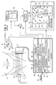
- Figure 1 shows an ultrasound device used to implement the method of the invention.
- This device comprises a display screen 1 for showing in real time the images produced.
- images are acquired on two different dates.
- the acquisition process apart from refining the invention, is the same in both cases.
- the acquisition process consists in a manner known per se of placing an ultrasound probe 2 against a region of the body of a patient 3.
- the region examined is the neck, and the application described is an arteriography app.
- the invention for other purposes, in particular for see the vascular tree of the lower, upper limbs or organs located in the patient's trunk: the stomach, the liver.
- the ultrasound machine conventionally comprises reception transmission means 4 for sending electrical signals to the probe 2.
- the electrical signals are transformed there into acoustic signals by piezoelectric transducers 5 of the probe 2.
- the electrical signals are for example pulses of high frequency (of the order of 10 MHz) and of short duration. These signals are transmitted, according to methods known in themselves, to the various transducers 5 so as to focus the shot in the shooting directions 6.
- the ultrasound system switches to reception in particular by the action of a multiplexer.
- the piezoelectric transducers 5 translate into electrical signals the acoustic excitations which they receive by reflection from the neck 7 of the patient.
- the reflected acoustic signals arrive at the transducers 6 later and later as a function of the distance separating the zone from which they originate from the probe 2.
- we fire in a neighboring direction for example direction 8, and the same reflected acoustic signals are measured.
- the organization of the scanning of the firing directions 6 and 8 as well as the reception of the acoustic signals are managed by a microprocessor 9.
- This microprocessor 9 manages in correspondence the line scans and the column scans of the display monitor 1. If the scanning of direction of fire is not of the lateral type, but on the contrary of the fan type, the display on the monitor 1 is organized accordingly.
- the measured signals correspond to the demodulated and filtered signals in an operation 10. Like this has already been indicated previously, rather than viewing as a video signal a demodulated filtered analog signal, use is increasingly being made of a digitization in one operation 60 of the analog signal.
- the digital signal is then transmitted to an image memory 11, the reading of which is also managed by the microprocessor 9.
- the microprocessor takes the information contained at each address of the cells of a memory page of the memory d image and uses them as luminance and / or chrominance signal to control in correspondence the brightness of a pixel on monitor 1.
- the images produced during this second acquisition are sent, in real time, directly to the monitor 1, nevertheless passing through the image memory 11.
- the image memory therefore comprises for each pixel address of the screen 1, brightness information corresponding to the digitized value of the acoustic signal detected in real time.
- pixel to pixel that is to say with the correct addresses
- the practitioner sees appear on screen contours 14 to 27 (as well as the asterisk 28).
- a pattern in an example a circle such as circle 35, which one can develop for all the pixels it contains the value m and l standard deviation ⁇ of the variation in brightness.
- the pattern 35 is preferably placed in a relatively stable place in the image: where the reflected and recovered signal varies little whatever the orientations taken by the probe.
- the standard deviation is calculated in a similar way. Just as the position of the indexes 15 to 26 and the position of the segments such as 27 have been stored as a stored image, the position of the pattern 36 can be stored as well as the values ⁇ 1 and m1 relating to the first image.
- these simple calculations can also be carried out by operators who permanently receive the luminosity information coming from the memory cells concerned.
- the gain control button 36 the practitioner is then able to vary the gain of the ultrasound system: that is to say the power of the acoustic signals emitted by the probe 5.
- the brightness values tend to become the same between the first and second images. We want them to be the same or as close as possible to each other.
- the brightness values actually represent the density of the material encountered. In fact, the denser the material encountered, the more the reflected signals will be numerous and the higher the average value m.
- the circle 35 is placed in a place where, moreover, the average is low.
- the orientation corresponds to an orientation relative to the vertical and shows in a hourly or anti-clockwise position of the probe in the vertical plane.
- the incidence shows, relative to an axis 36 passing through the patient's back, the anterior, posterior, lateral or intermediate orientation between these directions, of the probe.
- Figure 2 shows schematically the anatomy of the carotid artery segments.
- these indications already show the practitioner where and approximately how he should place his probe. These indications are roughly sufficient for the distance 52 in the simplest case where the superposition of the images is obtained by a translation of the real-time image is not greater than the size of the screen.
- FIG. 3 shows the image of the contours resulting from a first acquisition of a transverse section, oriented for example according to the orientation 37-38 indicated in FIG. 2. It could appear that the contours represented are insufficient to allow determination how high the first image was made. It has been realized, however, that such a situation does not occur because, on the one hand the vessels examined do not have constant diameters whatever their height and that, on the other hand, they are not vertically oriented. With respect to the vertical 39 (parallel to the edge 40 of the neck) against which the probe 2 slides, it can be determined that all the vessels form a certain angle such as 41. If we then move in height, upwards, this angle 41 causes a displacement oriented in the direction of arrow 42, of the images of the structures concerned.
Landscapes
- Health & Medical Sciences (AREA)
- Engineering & Computer Science (AREA)
- Life Sciences & Earth Sciences (AREA)
- Physics & Mathematics (AREA)
- Remote Sensing (AREA)
- Radar, Positioning & Navigation (AREA)
- General Health & Medical Sciences (AREA)
- Animal Behavior & Ethology (AREA)
- Biomedical Technology (AREA)
- Heart & Thoracic Surgery (AREA)
- Medical Informatics (AREA)
- Molecular Biology (AREA)
- Surgery (AREA)
- Biophysics (AREA)
- Pathology (AREA)
- Public Health (AREA)
- Veterinary Medicine (AREA)
- Radiology & Medical Imaging (AREA)
- Nuclear Medicine, Radiotherapy & Molecular Imaging (AREA)
- General Physics & Mathematics (AREA)
- Computer Networks & Wireless Communication (AREA)
- Acoustics & Sound (AREA)
- Human Computer Interaction (AREA)
- Vascular Medicine (AREA)
- Cardiology (AREA)
- Physiology (AREA)
- Ultra Sonic Daignosis Equipment (AREA)
- Measurement Of Velocity Or Position Using Acoustic Or Ultrasonic Waves (AREA)
Claims (6)
- Verfahren zur Erfassung von mit einem Echographie-Gerät erhaltenen medizinischen Echographie-Bildern, wobei das Gerät mit einem Bildschirm (1) zur Echtzeitdarstellung der erzeugten Bilder versehen ist, bei dem- man mit dem Gerät ein erstes Bild eines Bereiches des Körpers eines zu untersuchenden Patienten (3) gemäß einem einer Echographie-Sonde des Geräts eigenen Anstellwinkel und einem Neigungswinkel (11H) erfaßt (2 - 10),- ein Arzt später ein zweites Bild des gleichen Bereiches des Körpers des gleichen Patienten gemäß dem gleichen Anstellwinkel und Neigungswinkel der Sonde des gleichen Gerätes erfaßt,- und man die beiden erfaßten Bilder zum Beurteilen der Entwicklung des Körpers des Patienten zwischen dem Zeitpunkt des ersten Bildes und dem des zweiten Bildes vergleicht,
dadurch gekennzeichnet, daß- der Arzt im Verlauf des Erfassens des zweiten Bildes unterstützt wird, indem auf dem Bildschirm zur Echtzeitdarstellung ein Bild (14 - 27, 43) der Umrisse der im ersten Bild vorhandenen Strukturen erzeugt wird,- und daß der Arzt die Sonde in einer Weise bedient, daß die in Echtzeit sichtbaren Umrisse des zweiten Bildes sich dem Bild der bereits vorhandenen Umrisse des ersten Bildes überlagern. - Verfahren nach Patentanspruch 1, dadurch gekennzeichnet, daß- auf dem Bildschirm zur Echtzeitdarstellung auf das erste Bild bezogene Informationen (35, m, σ) bezüglich der Dichte des Körpergewebes,- und auf das zweite Bild bezogene Informationen bezüglich der Dichte des selben Körpergewebes dargestellt werden,- und daß der Arzt sein Gerät so regelt (36), damit diese Informationen bezüglich der Dichte miteinander vereinbar sind.
- Verfahren nach einem der Patentansprüche 1 oder 2, dadurch gekennzeichnet, daß- auf dem Bildschirm zur Echtzeitdarstellung unter anderem auf eines der folgenden Kennzeichen bezogene Anzeigen erzeugt werden: Anstellwinkel des ersten Bildes (11H), Nummer des Teilstückes des Körpers des ersten Bildes, (Name des Patienten, Datum des ersten Bildes).
- Verfahren nach einem der Patentansprüche 1 bis 3, dadurch gekennzeichnet, daß man zum Erzeugen des Bildes der Umrisse des ersten Bildes- ein erstes Bild speichert und zu einem späteren Zeitpunkt auf dem Bildschirm zur Echtzeitdarstellung darstellt,- auf diesem ersten gespeicherten und dargestellten Bild Indizes (14) mittels Steuertasten einstellt (13),- und zum Erzeugen einer diese Indizes auf dem Bildschirm verbindenden Kurve (27) eine Kurvenzeichnungs-Verarbeitung durchgeführt wird.
- Verfahren nach einem der Patentansprüche 1 bis 4, dadurch gekennzeichnet, daß zum Erfassen eines guten zweiten Bildes- der Arzt mehrere aufeinanderfolgende zweite Bilder in Echtzeit erfaßt, während die Sonde der Position des ersten Bildes nah ist, und daß der Echograph diese zweiten Bilder mit einem für ihn eigentümlichen Untersuchungstakt abgibt,- man diese zweiten Bilder speichert (17), und- man unter den zweiten Bildern zu einem späteren Zeitpunkt jenes als gut auswählt, das dem ersten Bild am ähnlichsten ist.
- Verfahren nach einem der Patentansprüche 1 bis 5, dadurch gekennzeichnet, daß man zum Erzeugen des Bildes der Umrisse des ersten Bildes- das erste Bild aus einer Serie aufeinanderfolgender Bilder auswählt.
Applications Claiming Priority (2)
| Application Number | Priority Date | Filing Date | Title |
|---|---|---|---|
| FR9006633A FR2662813B1 (fr) | 1990-05-29 | 1990-05-29 | Procede d'acquisition d'images d'echographie. |
| FR9006633 | 1990-05-29 |
Publications (2)
| Publication Number | Publication Date |
|---|---|
| EP0459853A1 EP0459853A1 (de) | 1991-12-04 |
| EP0459853B1 true EP0459853B1 (de) | 1995-02-01 |
Family
ID=9397029
Family Applications (1)
| Application Number | Title | Priority Date | Filing Date |
|---|---|---|---|
| EP91401237A Expired - Lifetime EP0459853B1 (de) | 1990-05-29 | 1991-05-14 | Verfahren zur Erfassung von Echographie-Bildern |
Country Status (5)
| Country | Link |
|---|---|
| US (1) | US5181513A (de) |
| EP (1) | EP0459853B1 (de) |
| JP (1) | JPH084592B2 (de) |
| DE (1) | DE69107122T2 (de) |
| FR (1) | FR2662813B1 (de) |
Families Citing this family (82)
| Publication number | Priority date | Publication date | Assignee | Title |
|---|---|---|---|---|
| US5291889A (en) * | 1991-05-23 | 1994-03-08 | Vanguard Imaging Ltd. | Apparatus and method for spatially positioning images |
| JP3759184B2 (ja) * | 1994-12-21 | 2006-03-22 | ジーイー横河メディカルシステム株式会社 | 超音波血流表示方法および装置 |
| US5782766A (en) * | 1995-03-31 | 1998-07-21 | Siemens Medical Systems, Inc. | Method and apparatus for generating and displaying panoramic ultrasound images |
| JPH08280684A (ja) * | 1995-04-18 | 1996-10-29 | Fujitsu Ltd | 超音波診断装置 |
| US5709206A (en) * | 1995-11-27 | 1998-01-20 | Teboul; Michel | Imaging system for breast sonography |
| US5906578A (en) * | 1997-06-18 | 1999-05-25 | Rajan; Govinda N. | Method and system for probe positioning in transesophageal echocardiography |
| US6004270A (en) * | 1998-06-24 | 1999-12-21 | Ecton, Inc. | Ultrasound system for contrast agent imaging and quantification in echocardiography using template image for image alignment |
| US6056691A (en) | 1998-06-24 | 2000-05-02 | Ecton, Inc. | System for collecting ultrasound imaging data at an adjustable collection image frame rate |
| AU4699999A (en) * | 1998-06-24 | 2000-01-10 | Ecton, Inc. | Ultrasonic imaging systems and methods |
| JP2000300557A (ja) * | 1999-04-22 | 2000-10-31 | Aloka Co Ltd | 超音波診断装置 |
| US6561979B1 (en) | 1999-09-14 | 2003-05-13 | Acuson Corporation | Medical diagnostic ultrasound system and method |
| US6468213B1 (en) | 1999-09-14 | 2002-10-22 | Ecton, Inc. | Medical diagnostic ultrasound system and method |
| US6312381B1 (en) | 1999-09-14 | 2001-11-06 | Acuson Corporation | Medical diagnostic ultrasound system and method |
| US6488625B1 (en) | 1999-09-14 | 2002-12-03 | Ecton, Inc. | Medical diagnostic ultrasound system and method |
| US6497664B1 (en) | 1999-09-14 | 2002-12-24 | Ecton, Inc. | Medical diagnostic ultrasound system and method |
| US6436039B1 (en) | 1999-09-14 | 2002-08-20 | Ecton, Inc. | Medicial diagnostic ultrasound system and method |
| USD445189S1 (en) | 1999-09-14 | 2001-07-17 | Ecton, Inc. | Medical diagnostic ultrasound system |
| US7678048B1 (en) | 1999-09-14 | 2010-03-16 | Siemens Medical Solutions Usa, Inc. | Medical diagnostic ultrasound system and method |
| US6508763B1 (en) | 1999-09-14 | 2003-01-21 | Ecton, Inc. | Medical diagnostic ultrasound system and method |
| US6524244B1 (en) | 1999-09-14 | 2003-02-25 | Ecton Inc. | Medical diagnostic ultrasound system and method |
| US6402693B1 (en) * | 2000-01-13 | 2002-06-11 | Siemens Medical Solutions Usa, Inc. | Ultrasonic transducer aligning system to replicate a previously obtained image |
| JP5361103B2 (ja) * | 2000-10-24 | 2013-12-04 | 株式会社東芝 | 画像処理装置 |
| US6824514B2 (en) * | 2002-10-11 | 2004-11-30 | Koninklijke Philips Electronics N.V. | System and method for visualizing scene shift in ultrasound scan sequence |
| US6835177B2 (en) * | 2002-11-06 | 2004-12-28 | Sonosite, Inc. | Ultrasonic blood vessel measurement apparatus and method |
| US7074187B2 (en) * | 2002-12-13 | 2006-07-11 | Selzer Robert H | System and method for improving ultrasound image acquisition and replication for repeatable measurements of vascular structures |
| US7927278B2 (en) * | 2002-12-13 | 2011-04-19 | California Institute Of Technology | Split-screen display system and standardized methods for ultrasound image acquisition and multi-frame data processing |
| US7727153B2 (en) * | 2003-04-07 | 2010-06-01 | Sonosite, Inc. | Ultrasonic blood vessel measurement apparatus and method |
| US20060230049A1 (en) * | 2005-04-12 | 2006-10-12 | General Electric Company | Method and apparatus for selecting preferred images for a current exam based on a previous exam |
| US9521961B2 (en) | 2007-11-26 | 2016-12-20 | C. R. Bard, Inc. | Systems and methods for guiding a medical instrument |
| EP2992825B1 (de) | 2007-11-26 | 2017-11-01 | C.R. Bard Inc. | Integriertes system zur intravaskulären platzierung eines katheters |
| US8781555B2 (en) | 2007-11-26 | 2014-07-15 | C. R. Bard, Inc. | System for placement of a catheter including a signal-generating stylet |
| US20100121437A1 (en) | 2008-04-16 | 2010-05-13 | Cardiovascular Technologies, Llc | Transvalvular intraannular band and chordae cutting for ischemic and dilated cardiomyopathy |
| US20100121435A1 (en) | 2008-04-16 | 2010-05-13 | Cardiovascular Technologies, Llc | Percutaneous transvalvular intrannular band for mitral valve repair |
| US11013599B2 (en) | 2008-04-16 | 2021-05-25 | Heart Repair Technologies, Inc. | Percutaneous transvalvular intraannular band for mitral valve repair |
| US11083579B2 (en) | 2008-04-16 | 2021-08-10 | Heart Repair Technologies, Inc. | Transvalvular intraanular band and chordae cutting for ischemic and dilated cardiomyopathy |
| US10456259B2 (en) | 2008-04-16 | 2019-10-29 | Heart Repair Technologies, Inc. | Transvalvular intraannular band for mitral valve repair |
| US9532724B2 (en) | 2009-06-12 | 2017-01-03 | Bard Access Systems, Inc. | Apparatus and method for catheter navigation using endovascular energy mapping |
| WO2011150376A1 (en) | 2010-05-28 | 2011-12-01 | C.R. Bard, Inc. | Apparatus for use with needle insertion guidance system |
| CN104169739B (zh) | 2011-10-28 | 2017-04-12 | 决策科学国际公司 | 超声成像中的扩频编码波形 |
| US9844359B2 (en) | 2013-09-13 | 2017-12-19 | Decision Sciences Medical Company, LLC | Coherent spread-spectrum coded waveforms in synthetic aperture image formation |
| CN104739452B (zh) | 2013-12-30 | 2019-02-12 | 深圳迈瑞生物医疗电子股份有限公司 | 一种超声成像装置及方法 |
| US9883847B2 (en) * | 2014-01-29 | 2018-02-06 | University Of Maryland, Baltimore | Ultrasound localization of obstruction for obstructive sleep apnea |
| JP6305280B2 (ja) * | 2014-08-28 | 2018-04-04 | 株式会社日立ハイテクサイエンス | 蛍光x線分析装置及びその試料表示方法 |
| US10743838B2 (en) | 2015-02-25 | 2020-08-18 | Decision Sciences Medical Company, LLC | Acoustic signal transmission couplants and coupling mediums |
| WO2016203288A1 (en) * | 2015-06-15 | 2016-12-22 | B-K Medical Aps | Display of imaging data in a moving viewport |
| CA3001315C (en) | 2015-10-08 | 2023-12-19 | Decision Sciences Medical Company, LLC | Acoustic orthopedic tracking system and methods |
| WO2017136535A1 (en) * | 2016-02-05 | 2017-08-10 | University Of Maryland, Baltimore | Automatic ultrasound titration of continuous positive airway pressure (cpap) treatment for sleep apnea |
| US11020563B2 (en) | 2016-07-14 | 2021-06-01 | C. R. Bard, Inc. | Automated catheter-to-vessel size comparison tool and related methods |
| WO2018119304A1 (en) | 2016-12-22 | 2018-06-28 | Heart Repair Technologies, Inc. | Percutaneous delivery systems for anchoring an implant in a cardiac valve annulus |
| CN112867443B (zh) | 2018-10-16 | 2024-04-26 | 巴德阿克塞斯系统股份有限公司 | 用于建立电连接的安全装备连接系统及其方法 |
| US12544101B2 (en) | 2019-01-30 | 2026-02-10 | Bard Access Systems, Inc. | Systems and methods for tracking medical devices |
| EP3923869A4 (de) | 2019-02-11 | 2022-11-09 | Heart Repair Technologies, Inc. | Perkutane verabreichungssysteme zur verankerung eines implantats in einem herzklappenring |
| US12017389B2 (en) | 2019-03-06 | 2024-06-25 | Decision Sciences Medical Company, LLC | Methods for manufacturing and distributing semi-rigid acoustic coupling articles and packaging for ultrasound imaging |
| US11154274B2 (en) | 2019-04-23 | 2021-10-26 | Decision Sciences Medical Company, LLC | Semi-rigid acoustic coupling articles for ultrasound diagnostic and treatment applications |
| US11759166B2 (en) | 2019-09-20 | 2023-09-19 | Bard Access Systems, Inc. | Automatic vessel detection tools and methods |
| CN113952031B (zh) | 2020-07-21 | 2025-10-17 | 巴德阿克塞斯系统股份有限公司 | 磁跟踪超声探头及生成其3d可视化的系统、方法和设备 |
| CN114052905A (zh) | 2020-08-04 | 2022-02-18 | 巴德阿克塞斯系统股份有限公司 | 用于优化的医疗部件插入监测和成像增强的系统和方法 |
| CN217907826U (zh) | 2020-08-10 | 2022-11-29 | 巴德阿克塞斯系统股份有限公司 | 医学分析系统 |
| CN114129181A (zh) | 2020-09-03 | 2022-03-04 | 巴德阿克塞斯系统股份有限公司 | 便携式超声探测器、系统和方法 |
| CN216135922U (zh) | 2020-09-08 | 2022-03-29 | 巴德阿克塞斯系统股份有限公司 | 动态调整超声成像系统 |
| CN114159098B (zh) | 2020-09-10 | 2026-01-02 | 巴德阿克塞斯系统股份有限公司 | 具有压力测量能力的超声探测器 |
| US12492953B2 (en) | 2020-09-18 | 2025-12-09 | Bard Access Systems, Inc. | Ultrasound probe with pointer remote control capability |
| CN114246614B (zh) | 2020-09-25 | 2025-09-23 | 巴德阿克塞斯系统股份有限公司 | 超声成像系统和最小导管长度工具 |
| WO2022072727A2 (en) | 2020-10-02 | 2022-04-07 | Bard Access Systems, Inc. | Ultrasound systems and methods for sustained spatial attention |
| CN121221162A (zh) | 2020-10-15 | 2025-12-30 | 巴德阿克塞斯系统股份有限公司 | 超声成像系统和使用其创建目标区域的三维超声图像的方法 |
| JP2023549818A (ja) | 2020-11-13 | 2023-11-29 | ディスィジョン サイエンシズ メディカル カンパニー,エルエルシー | 物体の合成開口超音波撮像のためのシステムおよび方法 |
| EP4247267A1 (de) | 2020-11-24 | 2023-09-27 | Bard Access Systems, Inc. | Ultraschallsystem mit ziel- und medizinischem instrumentenbewusstsein |
| CN114569155A (zh) | 2020-12-01 | 2022-06-03 | 巴德阿克塞斯系统股份有限公司 | 超声成像系统和用于通过其获得超声图像的方法 |
| WO2022119856A1 (en) | 2020-12-01 | 2022-06-09 | Bard Access Systems, Inc. | Ultrasound system with pressure and flow determination capability |
| WO2022132651A1 (en) | 2020-12-14 | 2022-06-23 | Bard Access Systems, Inc. | Securement of hands-free ultrasound probe |
| WO2022183159A1 (en) | 2021-02-26 | 2022-09-01 | Heart Repair Technologies, Inc. | Transvalvular intraannular implant for valve repair |
| CN217960146U (zh) | 2021-04-15 | 2022-12-06 | 巴德阿克塞斯系统股份有限公司 | 超声成像系统 |
| WO2023076308A1 (en) * | 2021-10-28 | 2023-05-04 | Howmedica Osteonics Corp. | Mixed reality guidance of ultrasound probe |
| US12376817B2 (en) | 2021-11-03 | 2025-08-05 | Bard Access Systems, Inc. | Optimized functionality through interoperation of doppler and image based vessel differentiation |
| US12514533B2 (en) | 2022-03-01 | 2026-01-06 | Bard Access Systems, Inc. | Ultrasound imaging system |
| US12514532B2 (en) | 2022-03-01 | 2026-01-06 | Bard Access Systems, Inc. | Ultrasound imaging system |
| EP4489661B1 (de) | 2022-03-16 | 2025-10-29 | Bard Access Systems, Inc. | Ultraschallbildgebungssystem |
| US12102481B2 (en) | 2022-06-03 | 2024-10-01 | Bard Access Systems, Inc. | Ultrasound probe with smart accessory |
| US12137989B2 (en) | 2022-07-08 | 2024-11-12 | Bard Access Systems, Inc. | Systems and methods for intelligent ultrasound probe guidance |
| US12564373B2 (en) | 2022-08-15 | 2026-03-03 | Bard Access Systems, Inc. | Spatially aware medical device configured for performance of insertion pathway approximation |
| CN116439742B (zh) * | 2023-06-14 | 2023-08-22 | 北京大学第一医院 | 一种颈部超声成像装置 |
| CN119323383B (zh) * | 2024-12-17 | 2025-03-14 | 贵州聚控云科技有限公司 | 一种公路混凝土层施工质量管理系统 |
Family Cites Families (9)
| Publication number | Priority date | Publication date | Assignee | Title |
|---|---|---|---|---|
| US4263916A (en) * | 1978-03-27 | 1981-04-28 | University Of Southern California | Image averaging for angiography by registration and combination of serial images |
| US4448200A (en) * | 1978-03-27 | 1984-05-15 | University Of Southern California | System and method for dynamic background subtraction |
| US4431007A (en) * | 1981-02-04 | 1984-02-14 | General Electric Company | Referenced real-time ultrasonic image display |
| FR2545349B1 (fr) * | 1983-05-04 | 1986-09-26 | Duret Francois | Procede de saisie de la forme d'organes humains ou d'anomalies pathologiques et dispositif pour sa mise en oeuvre |
| US4922909A (en) * | 1987-07-17 | 1990-05-08 | Little James H | Video monitoring and reapposition monitoring apparatus and methods |
| JPH0197441A (ja) * | 1987-10-09 | 1989-04-14 | Hitachi Medical Corp | 超音波診断装置 |
| JP2620946B2 (ja) * | 1987-11-13 | 1997-06-18 | 株式会社日立メディコ | 超音波診断装置 |
| JPH01139044A (ja) * | 1987-11-26 | 1989-05-31 | Yokogawa Medical Syst Ltd | 超音波診断装置 |
| JPH02114776A (ja) * | 1988-10-25 | 1990-04-26 | Toshiba Corp | X線診断装置 |
-
1990
- 1990-05-29 FR FR9006633A patent/FR2662813B1/fr not_active Expired - Lifetime
-
1991
- 1991-05-14 DE DE69107122T patent/DE69107122T2/de not_active Expired - Fee Related
- 1991-05-14 EP EP91401237A patent/EP0459853B1/de not_active Expired - Lifetime
- 1991-05-23 US US07/704,800 patent/US5181513A/en not_active Expired - Fee Related
- 1991-05-29 JP JP15398291A patent/JPH084592B2/ja not_active Expired - Lifetime
Also Published As
| Publication number | Publication date |
|---|---|
| JPH06169924A (ja) | 1994-06-21 |
| DE69107122D1 (de) | 1995-03-16 |
| JPH084592B2 (ja) | 1996-01-24 |
| US5181513A (en) | 1993-01-26 |
| FR2662813B1 (fr) | 1992-08-14 |
| FR2662813A1 (fr) | 1991-12-06 |
| EP0459853A1 (de) | 1991-12-04 |
| DE69107122T2 (de) | 1995-06-01 |
Similar Documents
| Publication | Publication Date | Title |
|---|---|---|
| EP0459853B1 (de) | Verfahren zur Erfassung von Echographie-Bildern | |
| EP1043952B1 (de) | Verwendung einer utraschallsonde zur auswertung der echographie des hinteren segmentes des augapfels | |
| EP0840139B1 (de) | Verarbeitungsverfahren für Signale von Objekten mit sich bewegenden Teilen und Echographie-Vorrichtung dafür | |
| JP5451492B2 (ja) | 画像処理装置、その制御方法及びプログラム | |
| EP3801761A1 (de) | Ultraschallverarbeitungsvorrichtung mit mitteln zur abbildung von kavitationsblasen | |
| JPH11318896A (ja) | 血管膜厚測定装置及び動脈硬化診断装置 | |
| EP1844438B1 (de) | Verfahren und system zur simulation oder digitalen synthese echographischer bilder | |
| EP1844439B1 (de) | Verfahren und system zur simulation oder digitalen synthese echographischer bilder | |
| FR2993768A1 (fr) | Systeme et procede d'imagerie echographique | |
| FR2849241A1 (fr) | Procede et dispositif d'imagerie radiographique | |
| JPWO2018087984A1 (ja) | 光音響画像評価装置、方法およびプログラム並びに光音響画像生成装置 | |
| EP0101336A2 (de) | Generator zur Verarbeitung eines Videosignals mit Kontrast für Strahlenkunde und Verfahren für derartige Signalverarbeitung | |
| EP0738988A1 (de) | Bildverarbeitungsverfahren und Vorrichtung zur automatischen Ermittlung von Objekten in numerischen Bildern | |
| Acharya U et al. | Imaging systems of human eye: a review | |
| FR3099984A1 (fr) | Changement de dynamique de mode de guidage d'imagerie par ultrasons | |
| FR2655835A1 (fr) | Appareil de detection de kystes et/ou tumeurs du sein. | |
| FR3136645A1 (fr) | Dispositif de génération d’une séquence d'images représentant une suite continue d’éléments osseux en mouvement | |
| Zheng et al. | Ultrasound imaging of human teeth using a desktop scanning acoustic microscope | |
| EP2378962A1 (de) | Verfahren zur messung des lokalen steifheitsindexes der wand einer leitenden arterie und entsprechende ausrüstung | |
| Restori et al. | C-scan ultrasonography in orbital diagnosis. | |
| JP2014087688A (ja) | 画像処理装置及びその制御方法 | |
| JP7479684B2 (ja) | 画像生成方法、画像生成プログラムおよび画像生成装置 | |
| JP2785679B2 (ja) | 生体組織多次元可視装置 | |
| WO2023232990A1 (fr) | Dispositif pour l'assistance au guidage pour acquerir une image echographique et procede associe | |
| JP3828450B2 (ja) | 超音波診断装置 |
Legal Events
| Date | Code | Title | Description |
|---|---|---|---|
| PUAI | Public reference made under article 153(3) epc to a published international application that has entered the european phase |
Free format text: ORIGINAL CODE: 0009012 |
|
| AK | Designated contracting states |
Kind code of ref document: A1 Designated state(s): BE DE GB IT SE |
|
| 17P | Request for examination filed |
Effective date: 19920421 |
|
| 17Q | First examination report despatched |
Effective date: 19940328 |
|
| GRAA | (expected) grant |
Free format text: ORIGINAL CODE: 0009210 |
|
| AK | Designated contracting states |
Kind code of ref document: B1 Designated state(s): BE DE GB IT SE |
|
| REF | Corresponds to: |
Ref document number: 69107122 Country of ref document: DE Date of ref document: 19950316 |
|
| GBT | Gb: translation of ep patent filed (gb section 77(6)(a)/1977) |
Effective date: 19950221 |
|
| ITF | It: translation for a ep patent filed | ||
| PGFP | Annual fee paid to national office [announced via postgrant information from national office to epo] |
Ref country code: SE Payment date: 19950530 Year of fee payment: 5 Ref country code: GB Payment date: 19950530 Year of fee payment: 5 |
|
| PGFP | Annual fee paid to national office [announced via postgrant information from national office to epo] |
Ref country code: BE Payment date: 19950531 Year of fee payment: 5 |
|
| PGFP | Annual fee paid to national office [announced via postgrant information from national office to epo] |
Ref country code: DE Payment date: 19950630 Year of fee payment: 5 |
|
| PLBE | No opposition filed within time limit |
Free format text: ORIGINAL CODE: 0009261 |
|
| STAA | Information on the status of an ep patent application or granted ep patent |
Free format text: STATUS: NO OPPOSITION FILED WITHIN TIME LIMIT |
|
| 26N | No opposition filed | ||
| PG25 | Lapsed in a contracting state [announced via postgrant information from national office to epo] |
Ref country code: GB Effective date: 19960514 |
|
| PG25 | Lapsed in a contracting state [announced via postgrant information from national office to epo] |
Ref country code: SE Effective date: 19960515 |
|
| PG25 | Lapsed in a contracting state [announced via postgrant information from national office to epo] |
Ref country code: BE Effective date: 19960531 |
|
| BERE | Be: lapsed |
Owner name: SOC. TRAITEMENT SYNTHESE IMAGE S.A.R.L. TSI Effective date: 19960531 Owner name: TOUBOUL PIERRE-JEAN Effective date: 19960531 |
|
| GBPC | Gb: european patent ceased through non-payment of renewal fee |
Effective date: 19960514 |
|
| PG25 | Lapsed in a contracting state [announced via postgrant information from national office to epo] |
Ref country code: DE Effective date: 19970201 |
|
| EUG | Se: european patent has lapsed |
Ref document number: 91401237.2 |
|
| PG25 | Lapsed in a contracting state [announced via postgrant information from national office to epo] |
Ref country code: IT Free format text: LAPSE BECAUSE OF NON-PAYMENT OF DUE FEES;WARNING: LAPSES OF ITALIAN PATENTS WITH EFFECTIVE DATE BEFORE 2007 MAY HAVE OCCURRED AT ANY TIME BEFORE 2007. THE CORRECT EFFECTIVE DATE MAY BE DIFFERENT FROM THE ONE RECORDED. Effective date: 20050514 |