EP0110819A2 - Dispositif pour séparer les personnes à l'entrée d'un domaine - Google Patents
Dispositif pour séparer les personnes à l'entrée d'un domaine Download PDFInfo
- Publication number
- EP0110819A2 EP0110819A2 EP83810439A EP83810439A EP0110819A2 EP 0110819 A2 EP0110819 A2 EP 0110819A2 EP 83810439 A EP83810439 A EP 83810439A EP 83810439 A EP83810439 A EP 83810439A EP 0110819 A2 EP0110819 A2 EP 0110819A2
- Authority
- EP
- European Patent Office
- Prior art keywords
- cabin
- shield
- door
- reveal
- door leaf
- Prior art date
- Legal status (The legal status is an assumption and is not a legal conclusion. Google has not performed a legal analysis and makes no representation as to the accuracy of the status listed.)
- Granted
Links
- 238000005192 partition Methods 0.000 claims abstract description 5
- 238000006073 displacement reaction Methods 0.000 claims 1
- 230000001960 triggered effect Effects 0.000 abstract 1
- 230000000694 effects Effects 0.000 description 3
- 238000000926 separation method Methods 0.000 description 3
- 238000010586 diagram Methods 0.000 description 2
- 238000005516 engineering process Methods 0.000 description 2
- 239000000463 material Substances 0.000 description 2
- 206010020400 Hostility Diseases 0.000 description 1
- 238000013475 authorization Methods 0.000 description 1
- 230000009194 climbing Effects 0.000 description 1
- 230000001419 dependent effect Effects 0.000 description 1
- 238000002955 isolation Methods 0.000 description 1
- 238000004519 manufacturing process Methods 0.000 description 1
- 238000000034 method Methods 0.000 description 1
- 238000012544 monitoring process Methods 0.000 description 1
- 238000010248 power generation Methods 0.000 description 1
- 230000000284 resting effect Effects 0.000 description 1
- 239000007787 solid Substances 0.000 description 1
- 230000000087 stabilizing effect Effects 0.000 description 1
Images


Classifications
-
- E—FIXED CONSTRUCTIONS
- E05—LOCKS; KEYS; WINDOW OR DOOR FITTINGS; SAFES
- E05G—SAFES OR STRONG-ROOMS FOR VALUABLES; BANK PROTECTION DEVICES; SAFETY TRANSACTION PARTITIONS
- E05G5/00—Bank protection devices
- E05G5/003—Entrance control
-
- G—PHYSICS
- G07—CHECKING-DEVICES
- G07C—TIME OR ATTENDANCE REGISTERS; REGISTERING OR INDICATING THE WORKING OF MACHINES; GENERATING RANDOM NUMBERS; VOTING OR LOTTERY APPARATUS; ARRANGEMENTS, SYSTEMS OR APPARATUS FOR CHECKING NOT PROVIDED FOR ELSEWHERE
- G07C9/00—Individual registration on entry or exit
- G07C9/10—Movable barriers with registering means
- G07C9/15—Movable barriers with registering means with arrangements to prevent the passage of more than one individual at a time
Definitions
- the present invention relates to a device for separating people when entering an area located behind a partition through a passage in the partition.
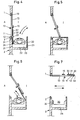
- a shield 30 is articulated by means of a hinge 12.
- a cabin 20 Connected to the opposite reveal 2 is a cabin 20, which is closed on three sides 21, 22 and 23 and is open on the fourth side 24 against the former reveal 1.
- the shield 30, as shown clearly in FIGS. 2 and 3, is rotatably supported approximately in the middle by means of a hinge 12 and has a dimension such that the open side 24 of the cabin 20 can be at least approximately completely closed.
- the interior of the cabin can be reduced by a chicane 25 in such a way that only one normal adult person has space between the sign 30 closing the open side 24 and the chicane.
- a window 26 can be provided in a side wall, through which a guard can check the person requesting access from a safe position.
- the cabin roof 27 is extended beyond the cabin. This can prevent an intruder from climbing over the shield and gaining unauthorized access when the door is partially open with the shield hinged.
- a room detector 43 and a cabin light 60 can be provided in the cabin itself, on the one hand to indicate that a person is present in the cabin 20 and to create an acceptable illuminated environment for this person. Furthermore, an electrical switch 41, an electrical door opener 38, a key switch 51, an alarm bell 44 can also be provided.
- FIGS. 4 to 6. 4 the door 10 is shown resting on both sides in the frames of the soffits 1 and 2.
- the shield 30 engages with a portion 31 in a guide rail 28 in the baffle 25 of the cabin. A person can thus enter the cabin 20 from the interior I. With the handle 17 on the shield 30, this person can now bring the shield into the position shown in FIG. 5. This completely encloses the person.
- the shield portion 32 which is directed towards the cabin wall 33 with its end face, can latch there.
- Such pawls are well known from the fitting technology and can be designed to be electrically releasable or releasable from the outside by hand.
- the person in the cabin 20 can no longer bring the door and the sign back into the position shown in FIG. 4.
- it can press the label on page 31 so that the position according to FIG. 6 is obtained.
- the person From the position shown in FIG. 4, the person must press the door 10 and the sign 30 into the position shown in FIG. 6 by actuating the handle 13. As a result, the sign snaps behind the lock on the wall 23 and access to the cabin 20 is only free from the outside.
- the entering person now pulls the sign into the position according to FIG. 5.
- the side 32 of the sign cannot solve the entering person alone, but needs either the help from the inside or a special key or a coded access card.
- the shield is formed in two parts and the two parts are arranged so as to be foldable with a vertical hinge arrangement 33.
- the hinge can be released by means of a safety rod (not shown), which can only be actuated from the inside, and the part 31 can be folded onto the part 32 and both parts can then together around the hinge 12 can be folded down on the inside of the door so that the door can be opened into a position as shown in FIG. 7, so that free passage is guaranteed in both directions.
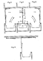
- FIGS. 8 to 11 A second variant of a door is shown in FIGS. 8 to 11.
- a cabin 60 of a hinge arrangement for doors 61 is arranged.
- the door 63 consists of two individual door leaf parts which are connected to one another in an articulated manner on the end face by means of a joint part 66.
- a plate 69 is articulated at the free end 70 of the two door parts.
- two stops 68 are arranged at a distance from one another in the lintel and one door is equipped with a resilient tilting pin, through which avoided can be that the two door parts 64, 65 are in a straight line.
- the two outer parts 71 and 72 of the shield 69 are provided with gripping elements 73 in the form of curved lugs, and round rods 74 are arranged next to the two side walls of the cabin 60 and are partially encompassed by the gripping elements.
- FIG. 8 If a person in FIG. 8 now enters the cabin 60 according to the drawn-out arrow, he can close the cabin by pulling the shield 69, as shown in FIG. 9.
- the door can be electrically locked either on one side or on both sides by means of the round bars 74 and the gripping elements 73.
- an automatic locking is provided on the inside I according to FIG. 9, so that a cabin once closed can no longer be opened towards the inside.
- the person in the cabin can then only open the door according to FIG. 10 and exit to the outside, as the arrow shown clearly shows.
- a person can also enter the cabin from the outside according to the dashed arrow in FIG. 10, then close the cabin according to FIG. 9 and, if access is permitted, open the door according to FIG. 8 in the direction 8 to leave the cabin 60 again.
- This door has the advantage that, due to the special arrangement of one of the two tabs 73, namely in such a way that it can be brought from a locking position into an open position in order to disengage it from the round rods to solve the shield together with the door from a position that is dashed in Figa. 11 is shown, can be brought into one of the two positions shown with solid lines.
- a hook 34 on the inner wall 24 of the cabin 20 is connected to a lifting magnet 39 on the cabin roof via a linkage.
- the solenoid When the solenoid is actuated, the hook 34 is raised and the door is locked.
- a third party can then release the lock from outside the cabin by actuating the push button 38.
- the lifting magnet 39 is de-energized when the cabin is empty.
- the hook 34 is thus in the rest position and the door can be brought into the position according to FIG. 4.
- the room detector 43 reports this and closes the circuit for the lifting magnet 39.
- the hook 34 is raised and the shield is locked on the side wall 24. So that the person in the cabin can get into the interior, the current through the lifting magnet 39 must be interrupted again.
- switch 41 in the cabin wall which can be implemented as a key switch as a code entry device or as a card reader.
- a remotely located safety switch 42 would also be conceivable, which can be actuated from a command point within a secured room.
- a vacant cabin can be indicated with a green lamp 47 and the occupied cabin with a red lamp 46.
- a relay 45 can be attached in the circuit for the magnet 39, which switches the lamp 47 to the current-carrying phase P with contacts 45 in the dropped state and the lamp 46 in the tightened state
- Lamp 46 may be switched on either to indicate outside that there is a person in the cabin or to indicate at the control desk that a person is in the cabin so that the authorization can be checked via an intercom.
- a sign attached to the front edge of a hinged door prevents other people from being forced into it. This can solve the problem the strict isolation of persons recognized as authorized during the entry and exit process is well resolved and absolute restraint is achieved against unauthorized persons.
- the shield in front of the door edge is not rigid but flexible.
- the sign does not have to be moved beyond the cabin, but can be moved via a guide inside the cabin, and secondly, the cabin does not have to be aligned with the axis of the door in the middle position.
- Another advantage is that after pulling out a rod stabilizing the shield, it can be folded in about the middle and can thus be swiveled out of the area of the cabin in order to easily clear the entire passage for the way.
- the chicane in the cabin can prevent with absolute certainty that more than one person is in the cabin. If several people nevertheless pushed into the cabin, the shield would automatically block and could no longer be turned.
- the door can be pivoted open completely by the shield being able to be pivoted into an ineffective position after a lock has been released. This means that any goods can be transported with a normally open passage.
Landscapes
- Physics & Mathematics (AREA)
- General Physics & Mathematics (AREA)
- Business, Economics & Management (AREA)
- Accounting & Taxation (AREA)
- Finance (AREA)
- Lock And Its Accessories (AREA)
- Devices For Checking Fares Or Tickets At Control Points (AREA)
- Power-Operated Mechanisms For Wings (AREA)
- Specific Sealing Or Ventilating Devices For Doors And Windows (AREA)
Priority Applications (1)
| Application Number | Priority Date | Filing Date | Title |
|---|---|---|---|
| AT83810439T ATE48197T1 (de) | 1982-09-29 | 1983-09-29 | Vorrichtung zum vereinzeln von personen beim betreten eines gebietes. |
Applications Claiming Priority (2)
| Application Number | Priority Date | Filing Date | Title |
|---|---|---|---|
| CH5714/82A CH647838A5 (de) | 1982-09-29 | 1982-09-29 | Vorrichtung zur vereinzelung von personen zwecks verhinderung des zutritts unbefugter in die dahinterliegenden raeume. |
| CH5714/82 | 1982-09-29 |
Publications (3)
| Publication Number | Publication Date |
|---|---|
| EP0110819A2 true EP0110819A2 (fr) | 1984-06-13 |
| EP0110819A3 EP0110819A3 (en) | 1987-04-29 |
| EP0110819B1 EP0110819B1 (fr) | 1989-11-23 |
Family
ID=4298150
Family Applications (1)
| Application Number | Title | Priority Date | Filing Date |
|---|---|---|---|
| EP83810439A Expired EP0110819B1 (fr) | 1982-09-29 | 1983-09-29 | Dispositif pour séparer les personnes à l'entrée d'un domaine |
Country Status (4)
| Country | Link |
|---|---|
| EP (1) | EP0110819B1 (fr) |
| AT (1) | ATE48197T1 (fr) |
| CH (1) | CH647838A5 (fr) |
| DE (1) | DE3380885D1 (fr) |
Cited By (9)
| Publication number | Priority date | Publication date | Assignee | Title |
|---|---|---|---|---|
| FR2731462A1 (fr) * | 1995-03-07 | 1996-09-13 | Tech Et Securite | Porte a battant pivotant et sas equipe de cette porte |
| WO1997020290A1 (fr) * | 1995-11-27 | 1997-06-05 | Alex Huber | Dispositif pour isoler des personnes |
| NL1003379C2 (nl) * | 1996-06-19 | 1997-12-23 | W Van Den Hoogen B V | Inrichting voor het controleren van de toegang tot een ruimte. |
| FR2773249A1 (fr) * | 1997-11-24 | 1999-07-02 | Huber Alex | Dispositif pour separer des personnes |
| WO1999055995A1 (fr) * | 1998-04-29 | 1999-11-04 | Malcolm William Thomas | Systeme de commande d'acces |
| EP1143386A1 (fr) * | 2000-04-06 | 2001-10-10 | MS Security AG | Dispositif de passage |
| FR2855549A1 (fr) * | 2003-05-28 | 2004-12-03 | Serrurerie Ginon | Dispositif d'acces securise a un local |
| EP1672162A3 (fr) * | 2004-12-16 | 2007-02-21 | Anton Posch | Portes |
| ITUB20155357A1 (it) * | 2015-11-03 | 2017-05-03 | Enzo Anselmi | Dispositivo di controllo accessi a unicita' di passaggio |
Families Citing this family (3)
| Publication number | Priority date | Publication date | Assignee | Title |
|---|---|---|---|---|
| CH676621A5 (en) * | 1988-03-17 | 1991-02-15 | Schneebeli Metallbau Ag | Turnstile with inner and outer gates - has swivelling baffle plate, increasing inner space in end position |
| CH687632A5 (de) * | 1992-09-25 | 1997-01-15 | Schneebeli Metallbau Ag | Sicherheits-Personenschleuse. |
| EP2775081A3 (fr) | 2013-03-07 | 2018-03-14 | Eugster Sicherheitstechnik | Dispositif destiné à la réception et à la libération régulées d'un entraîneur |
Family Cites Families (10)
| Publication number | Priority date | Publication date | Assignee | Title |
|---|---|---|---|---|
| GB107046A (fr) * | ||||
| GB302957A (en) * | 1927-09-21 | 1928-12-21 | Joseph Devonport Finney Andrew | Coin freed apparatus for closet doors |
| US1845743A (en) * | 1930-12-11 | 1932-02-16 | Verna E Davidson | Door construction |
| US2662253A (en) * | 1951-07-10 | 1953-12-15 | William R Winkler | Door for darkrooms |
| US3169329A (en) * | 1962-05-31 | 1965-02-16 | Universal Controls Inc | Turnstile |
| US3445963A (en) * | 1967-07-21 | 1969-05-27 | Roto Swing Door Co Inc | Panic breakaway balance door |
| US3955322A (en) * | 1973-07-02 | 1976-05-11 | Call Jr Charles W | Entry lock |
| DE2735780C3 (de) * | 1977-08-09 | 1981-04-23 | Bochumer Eisenhütte Heintzmann GmbH & Co, 4630 Bochum | Vorrichtung zum Überprüfen von Personen |
| FR2411952A1 (fr) * | 1977-12-13 | 1979-07-13 | Decaux Publicite Abribus J C | Porte a serrure a condamnation |
| GB2041053B (en) * | 1979-01-31 | 1983-01-12 | Pretini Gisberto | Protective door systems |
-
1982
- 1982-09-29 CH CH5714/82A patent/CH647838A5/de not_active IP Right Cessation
-
1983
- 1983-09-29 DE DE8383810439T patent/DE3380885D1/de not_active Expired
- 1983-09-29 EP EP83810439A patent/EP0110819B1/fr not_active Expired
- 1983-09-29 AT AT83810439T patent/ATE48197T1/de not_active IP Right Cessation
Cited By (11)
| Publication number | Priority date | Publication date | Assignee | Title |
|---|---|---|---|---|
| FR2731462A1 (fr) * | 1995-03-07 | 1996-09-13 | Tech Et Securite | Porte a battant pivotant et sas equipe de cette porte |
| WO1997020290A1 (fr) * | 1995-11-27 | 1997-06-05 | Alex Huber | Dispositif pour isoler des personnes |
| NL1003379C2 (nl) * | 1996-06-19 | 1997-12-23 | W Van Den Hoogen B V | Inrichting voor het controleren van de toegang tot een ruimte. |
| FR2773249A1 (fr) * | 1997-11-24 | 1999-07-02 | Huber Alex | Dispositif pour separer des personnes |
| WO1999055995A1 (fr) * | 1998-04-29 | 1999-11-04 | Malcolm William Thomas | Systeme de commande d'acces |
| AU756199B2 (en) * | 1998-04-29 | 2003-01-09 | Malcolm William Thomas | An access control system |
| EP1143386A1 (fr) * | 2000-04-06 | 2001-10-10 | MS Security AG | Dispositif de passage |
| EP1189178A1 (fr) * | 2000-04-06 | 2002-03-20 | Karl Schlierenzauer | Dispositif de passage |
| FR2855549A1 (fr) * | 2003-05-28 | 2004-12-03 | Serrurerie Ginon | Dispositif d'acces securise a un local |
| EP1672162A3 (fr) * | 2004-12-16 | 2007-02-21 | Anton Posch | Portes |
| ITUB20155357A1 (it) * | 2015-11-03 | 2017-05-03 | Enzo Anselmi | Dispositivo di controllo accessi a unicita' di passaggio |
Also Published As
| Publication number | Publication date |
|---|---|
| DE3380885D1 (en) | 1989-12-28 |
| ATE48197T1 (de) | 1989-12-15 |
| EP0110819A3 (en) | 1987-04-29 |
| CH647838A5 (de) | 1985-02-15 |
| EP0110819B1 (fr) | 1989-11-23 |
Similar Documents
| Publication | Publication Date | Title |
|---|---|---|
| DE2702810A1 (de) | Schutzeinrichtung gegen das eindringen von personen mit schlechten absichten in einen raum | |
| EP0110819B1 (fr) | Dispositif pour séparer les personnes à l'entrée d'un domaine | |
| DE2830936C2 (de) | Sicherheitszelle zur Abwicklung von Bankgeschäften o.dgl. | |
| DE3700891C2 (fr) | ||
| DE9318001U1 (de) | Schloß | |
| EP2387010A1 (fr) | Dispositif de sécurisation de porte d'issue de secours | |
| DE19527801A1 (de) | Schließsystem | |
| DE2902193A1 (de) | Sicherheitsschloss | |
| EP1110189A1 (fr) | Dispositif de releve de la situation destine a la reconnaissance du blocage de portes, portails ou analogues | |
| EP1496186B1 (fr) | Sas pour le controle du passage de personnes | |
| DE69904461T2 (de) | Zugangskontrollsystem | |
| DE3730031A1 (de) | Drehtuer | |
| DE68920718T2 (de) | Blockierung des Riegels eines Schlosses. | |
| EP0661080A1 (fr) | Dispositif coupe-feu pour système de transport traversant un mur | |
| EP1405974B1 (fr) | Mécanisme de verrouillage pour fenêtre ou porte oscillobattante | |
| EP3859111B1 (fr) | Installation de blocage pour une porte de protection contre l'incendie ou la fumée et agencement doté d'une telle installation | |
| DE19546035A1 (de) | Datensicherungs- und/oder Wertschutzschrank | |
| EP1189178A1 (fr) | Dispositif de passage | |
| EP0364648A1 (fr) | Sas pour le passage de personnes | |
| EP1219765A1 (fr) | Dispositif de sécurité pour une porte de sortie de secours | |
| DE19723025C2 (de) | Schaltungsanordnung für Schließungen von elektrischen Türanlagen, die im Gefahrenfall weder durch Druck noch durch Sog geöffnet werden dürfen | |
| DE4218661A1 (de) | Sicherheits-Eintrittsschleuse mit Metalldetektor | |
| DE3505305A1 (de) | Sicherheitsschrank fuer zur staendigen handhabung bereitliegende bargeldbestaende oder wertsachen | |
| DE1584269C (de) | Sicherungseinnchtung gegen Be raubung an einem Zahltisch | |
| DE29820761U1 (de) | Vorrichtung zum Vereinzeln von Personen |
Legal Events
| Date | Code | Title | Description |
|---|---|---|---|
| PUAI | Public reference made under article 153(3) epc to a published international application that has entered the european phase |
Free format text: ORIGINAL CODE: 0009012 |
|
| AK | Designated contracting states |
Designated state(s): AT BE CH DE FR GB IT LI LU NL SE |
|
| PUAL | Search report despatched |
Free format text: ORIGINAL CODE: 0009013 |
|
| AK | Designated contracting states |
Kind code of ref document: A3 Designated state(s): AT BE CH DE FR GB IT LI LU NL SE |
|
| 17P | Request for examination filed |
Effective date: 19871005 |
|
| RAP1 | Party data changed (applicant data changed or rights of an application transferred) |
Owner name: HUBER, ALEX |
|
| 17Q | First examination report despatched |
Effective date: 19880708 |
|
| GRAA | (expected) grant |
Free format text: ORIGINAL CODE: 0009210 |
|
| AK | Designated contracting states |
Kind code of ref document: B1 Designated state(s): AT BE CH DE FR GB IT LI LU NL SE |
|
| REF | Corresponds to: |
Ref document number: 48197 Country of ref document: AT Date of ref document: 19891215 Kind code of ref document: T |
|
| GBT | Gb: translation of ep patent filed (gb section 77(6)(a)/1977) | ||
| REF | Corresponds to: |
Ref document number: 3380885 Country of ref document: DE Date of ref document: 19891228 |
|
| ITF | It: translation for a ep patent filed | ||
| ET | Fr: translation filed | ||
| REG | Reference to a national code |
Ref country code: CH Ref legal event code: PLI Owner name: KLAEY & CO. SICHERHEITSBESCHLAEGE |
|
| PLBE | No opposition filed within time limit |
Free format text: ORIGINAL CODE: 0009261 |
|
| STAA | Information on the status of an ep patent application or granted ep patent |
Free format text: STATUS: NO OPPOSITION FILED WITHIN TIME LIMIT |
|
| 26N | No opposition filed | ||
| ITTA | It: last paid annual fee | ||
| EPTA | Lu: last paid annual fee | ||
| EAL | Se: european patent in force in sweden |
Ref document number: 83810439.6 |
|
| PGFP | Annual fee paid to national office [announced via postgrant information from national office to epo] |
Ref country code: SE Payment date: 19970814 Year of fee payment: 15 Ref country code: AT Payment date: 19970814 Year of fee payment: 15 |
|
| PGFP | Annual fee paid to national office [announced via postgrant information from national office to epo] |
Ref country code: GB Payment date: 19970815 Year of fee payment: 15 |
|
| PGFP | Annual fee paid to national office [announced via postgrant information from national office to epo] |
Ref country code: BE Payment date: 19970822 Year of fee payment: 15 |
|
| PGFP | Annual fee paid to national office [announced via postgrant information from national office to epo] |
Ref country code: LU Payment date: 19970916 Year of fee payment: 15 |
|
| PGFP | Annual fee paid to national office [announced via postgrant information from national office to epo] |
Ref country code: NL Payment date: 19970930 Year of fee payment: 15 |
|
| PG25 | Lapsed in a contracting state [announced via postgrant information from national office to epo] |
Ref country code: LU Free format text: LAPSE BECAUSE OF NON-PAYMENT OF DUE FEES Effective date: 19980929 Ref country code: GB Free format text: LAPSE BECAUSE OF NON-PAYMENT OF DUE FEES Effective date: 19980929 Ref country code: AT Free format text: LAPSE BECAUSE OF NON-PAYMENT OF DUE FEES Effective date: 19980929 |
|
| PG25 | Lapsed in a contracting state [announced via postgrant information from national office to epo] |
Ref country code: SE Free format text: LAPSE BECAUSE OF NON-PAYMENT OF DUE FEES Effective date: 19980930 Ref country code: BE Free format text: LAPSE BECAUSE OF NON-PAYMENT OF DUE FEES Effective date: 19980930 |
|
| BERE | Be: lapsed |
Owner name: HUBER ALEX Effective date: 19980930 |
|
| PG25 | Lapsed in a contracting state [announced via postgrant information from national office to epo] |
Ref country code: NL Free format text: LAPSE BECAUSE OF NON-PAYMENT OF DUE FEES Effective date: 19990401 |
|
| GBPC | Gb: european patent ceased through non-payment of renewal fee |
Effective date: 19980929 |
|
| EUG | Se: european patent has lapsed |
Ref document number: 83810439.6 |
|
| NLV4 | Nl: lapsed or anulled due to non-payment of the annual fee |
Effective date: 19990401 |
|
| PGFP | Annual fee paid to national office [announced via postgrant information from national office to epo] |
Ref country code: FR Payment date: 20000911 Year of fee payment: 18 |
|
| PGFP | Annual fee paid to national office [announced via postgrant information from national office to epo] |
Ref country code: DE Payment date: 20000925 Year of fee payment: 18 |
|
| PG25 | Lapsed in a contracting state [announced via postgrant information from national office to epo] |
Ref country code: DE Free format text: LAPSE BECAUSE OF NON-PAYMENT OF DUE FEES Effective date: 20020501 |
|
| PG25 | Lapsed in a contracting state [announced via postgrant information from national office to epo] |
Ref country code: FR Free format text: LAPSE BECAUSE OF NON-PAYMENT OF DUE FEES Effective date: 20020531 |
|
| REG | Reference to a national code |
Ref country code: FR Ref legal event code: ST |
|
| PGFP | Annual fee paid to national office [announced via postgrant information from national office to epo] |
Ref country code: CH Payment date: 20020826 Year of fee payment: 20 |
|
| PG25 | Lapsed in a contracting state [announced via postgrant information from national office to epo] |
Ref country code: LI Free format text: LAPSE BECAUSE OF EXPIRATION OF PROTECTION Effective date: 20030928 Ref country code: CH Free format text: LAPSE BECAUSE OF EXPIRATION OF PROTECTION Effective date: 20030928 |
|
| REG | Reference to a national code |
Ref country code: CH Ref legal event code: PL |