EP0111024B1 - Innenpumpe - Google Patents
Innenpumpe Download PDFInfo
- Publication number
- EP0111024B1 EP0111024B1 EP82111481A EP82111481A EP0111024B1 EP 0111024 B1 EP0111024 B1 EP 0111024B1 EP 82111481 A EP82111481 A EP 82111481A EP 82111481 A EP82111481 A EP 82111481A EP 0111024 B1 EP0111024 B1 EP 0111024B1
- Authority
- EP
- European Patent Office
- Prior art keywords
- stretch tube
- motor
- gap
- wet
- grooves
- Prior art date
- Legal status (The legal status is an assumption and is not a legal conclusion. Google has not performed a legal analysis and makes no representation as to the accuracy of the status listed.)
- Expired
Links
Images



Classifications
-
- G—PHYSICS
- G21—NUCLEAR PHYSICS; NUCLEAR ENGINEERING
- G21C—NUCLEAR REACTORS
- G21C15/00—Cooling arrangements within the pressure vessel containing the core; Selection of specific coolants
- G21C15/24—Promoting flow of the coolant
- G21C15/243—Promoting flow of the coolant for liquids
-
- F—MECHANICAL ENGINEERING; LIGHTING; HEATING; WEAPONS; BLASTING
- F04—POSITIVE - DISPLACEMENT MACHINES FOR LIQUIDS; PUMPS FOR LIQUIDS OR ELASTIC FLUIDS
- F04D—NON-POSITIVE-DISPLACEMENT PUMPS
- F04D29/00—Details, component parts, or accessories
- F04D29/08—Sealings
- F04D29/10—Shaft sealings
- F04D29/106—Shaft sealings especially adapted for liquid pumps
- F04D29/108—Shaft sealings especially adapted for liquid pumps the sealing fluid being other than the working liquid or being the working liquid treated
-
- Y—GENERAL TAGGING OF NEW TECHNOLOGICAL DEVELOPMENTS; GENERAL TAGGING OF CROSS-SECTIONAL TECHNOLOGIES SPANNING OVER SEVERAL SECTIONS OF THE IPC; TECHNICAL SUBJECTS COVERED BY FORMER USPC CROSS-REFERENCE ART COLLECTIONS [XRACs] AND DIGESTS
- Y02—TECHNOLOGIES OR APPLICATIONS FOR MITIGATION OR ADAPTATION AGAINST CLIMATE CHANGE
- Y02E—REDUCTION OF GREENHOUSE GAS [GHG] EMISSIONS, RELATED TO ENERGY GENERATION, TRANSMISSION OR DISTRIBUTION
- Y02E30/00—Energy generation of nuclear origin
- Y02E30/30—Nuclear fission reactors
Definitions
- the present invention relates to a wet-motor type internal pump for circulating cooling water through a nuclear reactor.
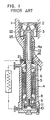
- Fig. 1 shows a conventional internal pump for circulating cooling water through a nuclear reactor.
- This pump is a wet-motor type pump installed on the bottom of the pressure vessel 1 of the nuclear reactor.
- This internal pump has an impeller 2 and a diffuser 3 which are disposed in the pressure vessel 1, and a motor case which accommodates various parts such as a motor rotor 5, motor stator 6, upper journal bearing 7, lowerjournal bearing 8, thrust bearing pads 9 and 10 and a thrust bearing disc 11 which serves also as an auxiliary impeller for motor cooling water.
- the diffuser 3 is stretched by a stretch tube 13 and a nut 14 so as to be pressed against the upper end surface of the bottom of the pressure vessel 1.
- the impeller 2 and the motor rotor 5 are coupled to each other through a shaft 12.
- the water temperature in the pressure vessel 1 is as high as 300°C.
- the water temperature for cooling the motor should be maintained sufficiently low, e.g. at 40°C.
- the water in the motor case 4 is forcibly circulated between the internal space of the motor case and an external heat exchanger by means of the auxiliary impeller 11 so as to discharge the heat generated in the motor and the heat transmitted from the pressure vessel 1.
- the pump is stopped while the nuclear reactor is operating, the forced circulation of cooling water by the auxiliary impeller 11 cannot be performed any more, so that the removal of heat transmitted from the pressure vessel 1 is achieved solely by the natural convection of water which is caused by the water temperature difference in the motor case 2.
- the purge water poured from the port 21 flows into the gap between the nozzle 4a of the motor case 4 and the nut 14 and then introduced into the lower gap 23 between the shaft 12 and the stretch tube 13 through one or more apertures 13a formed in the stretch tube 13. The water then flows through the upper gap 24 into a gap 25.
- a labyrinth 13c is provided on the portion surrounded by an ellipse III (see Fig. 2) of the inner peripheral surface of the stretch tube 13 so as to further improve the cooling effect.
- the passage for the purge water is determined such that the purge water poured from the outside of the motor case in the region near the lower end of the stretch tube flows not only into the gap between the shaft and the stretch tube but also into the gap between the stretch tube and the motor case nozzle and is discharged into the pressure vessel of the nuclear reactor through the gap between the impeller and the diffuser of the pump.
- FIG. 4 through 10 A first embodiment of the invention will be described hereinunder with specific reference to Figs. 4 through 10.
- the same reference numerals are used to denote the same parts or members as those used in Figs. 1 through 3, and detailed explanation of such parts or members is omitted for the simplification of description.
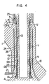
- Fig. 4 shows the construction of an internal pump carrying out the present invention.
- One or more holes 13b are formed in the portion of the stretch tube 13 near the upper end thereof.
- vertical grooves 13d are formed in the outer peripheral surface of the stretch tube 13 in the areas surrounded by an ellipse V of the motor case nozzle 4a where the distance between the stretch tube 13 and the motor nozzle 4a is extremely small.
- the winding groove 13f is constituted by a plurality of circumferential grooves 13f' in the outer peripheral surface of the stretch tube 13 and notches 13f" formed alternatingly at a 90° offset in the flanges separating the circumferential grooves 13f', so that the purge water introduced into the gap 26 is made to wind with respect to the axis of the stretch tube 13. It is possible to adopt the screw-thread groove shown in Fig. 7 or a winding groove shown in Fig. 8 in the area surrounded by an ellipse Y in Fig. 4. By so doing, it is possible to further uniformalize the circumferential temperature distribution.
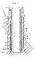
- Fig. 11 shows an internal pump in accordance with a second embodiment of the invention in which the same reference numerals are used to denote the same parts or members as those appearing in Figs. 4 through 10, and detailed description of such parts or members is omitted.
- the nozzle 4a of the motor case 4 is provided in its inner surface with a circumferential recess 31 which cooperates with the external surface of the stretch tube 13 in defining a gap similar to the gap 26 shown in Fig. 4.
- a compression force of the same level as the tensile force loading the stretch tube is applied to a thermal sleeve 33 through a stretch tube nut 32.
- the thermal tube 33 is disposed coaxially with the stretch tube 13 within a gap defined by the recess 33 and the outer peripheral surface of the stretch tube 13 so as to divide the space of the gap into radial inner and outer gap sections 34 and 35.
- the thermal sleeve 33 is provided with one or more lower holes 33a across the thickness thereof at a portion near the port 21, as well as one or more upper holes 33b formed across the thickness thereof at portions away from the port 21.
- the holes 13a and 13b in the stretch tube 13 and the holes 33a and 33b in the thermal sleeve 33 permits the purge water to flow not only through the gap 24 between the shaft 12 and the stretch tube 13 but also through the inner gap section 34 between the stretch tube 13 and the thermal sleeve 33, as well as the outer gap section 35 between the thermal sleeve 33 and the motor case nozzle 4a, to reach the gap 25.
- the stretch tube 13 taking the radially innermost position is kept at a temperature lower than the thermal sleeve 33 which in turn is kept at the temperature which is lowerthan the motor case nozzle 4a taking the radially outermost position. It is, therefore, possible to reduce the tensile thermal stress generated in the stretch tube 13. This effect is remarkable particularly when the temperature of the motor case nozzle changes abruptly as in the transient period of operation of the nuclear reactor, so that the application of excessive thermal stress on the stretch tube loaded with initial tensile stress is avoided effectively.
- the stretch tube 13 and the thermal sleeve 33 are made to have an equal cross- sectional area perpendicular to the axis, the thermal expansion of the thermal sleeve is effectively born by the compression deformation of the thermal sleeve 33 and the tensile deformation of the stretch tube 13, so that the thermal stress generated in the stretch tube 13 can be further decreased advantageously.
Landscapes
- Engineering & Computer Science (AREA)
- Physics & Mathematics (AREA)
- General Engineering & Computer Science (AREA)
- Plasma & Fusion (AREA)
- High Energy & Nuclear Physics (AREA)
- Mechanical Engineering (AREA)
- Structures Of Non-Positive Displacement Pumps (AREA)
- Glass Compositions (AREA)
Claims (6)
Priority Applications (3)
| Application Number | Priority Date | Filing Date | Title |
|---|---|---|---|
| DE8282111481T DE3276601D1 (en) | 1982-12-10 | 1982-12-10 | Internal pump |
| AT82111481T ATE27870T1 (de) | 1982-12-10 | 1982-12-10 | Innenpumpe. |
| EP82111481A EP0111024B1 (de) | 1982-12-10 | 1982-12-10 | Innenpumpe |
Applications Claiming Priority (1)
| Application Number | Priority Date | Filing Date | Title |
|---|---|---|---|
| EP82111481A EP0111024B1 (de) | 1982-12-10 | 1982-12-10 | Innenpumpe |
Publications (2)
| Publication Number | Publication Date |
|---|---|
| EP0111024A1 EP0111024A1 (de) | 1984-06-20 |
| EP0111024B1 true EP0111024B1 (de) | 1987-06-16 |
Family
ID=8189389
Family Applications (1)
| Application Number | Title | Priority Date | Filing Date |
|---|---|---|---|
| EP82111481A Expired EP0111024B1 (de) | 1982-12-10 | 1982-12-10 | Innenpumpe |
Country Status (3)
| Country | Link |
|---|---|
| EP (1) | EP0111024B1 (de) |
| AT (1) | ATE27870T1 (de) |
| DE (1) | DE3276601D1 (de) |
Families Citing this family (5)
| Publication number | Priority date | Publication date | Assignee | Title |
|---|---|---|---|---|
| FR2607874B1 (fr) * | 1986-12-09 | 1991-04-19 | Alsthom | Dispositif de sortie d'arbre pour pompe a eau sous hautes pression et temperature, notamment pour pompe alimentaire de centrale electrique a vapeur |
| EP0325230B1 (de) * | 1988-01-18 | 1994-10-12 | Kabushiki Kaisha Toshiba | Interne Pumpe für Kernreaktor |
| US5143515A (en) * | 1990-08-09 | 1992-09-01 | Bw/Ip International, Inc. | Pump with seal purge heater |
| JPH0664183B2 (ja) * | 1990-10-26 | 1994-08-22 | 株式会社荏原製作所 | 高温ポンプの熱疲労防止装置 |
| WO1997011469A1 (fr) * | 1995-09-18 | 1997-03-27 | Hitachi, Ltd. | Pompe interne |
Family Cites Families (4)
| Publication number | Priority date | Publication date | Assignee | Title |
|---|---|---|---|---|
| US3074348A (en) * | 1959-02-17 | 1963-01-22 | Atomic Energy Authority Uk | Centrifugal pumps |
| DE1514174C3 (de) * | 1965-07-23 | 1974-08-29 | Licentia Patent-Verwaltungs-Gmbh, 6000 Frankfurt | Siedewasserreaktor mit Zwangsumlauf des Kühlmittels |
| SE320739B (de) * | 1968-09-24 | 1970-02-16 | Asea Ab | |
| DE2259832C2 (de) * | 1972-12-07 | 1974-02-28 | Klein, Schanzlin & Becker Ag, 6710 Frankenthal | Gekühltes Radiallager innerhalb eines Tragrohres |
-
1982
- 1982-12-10 AT AT82111481T patent/ATE27870T1/de not_active IP Right Cessation
- 1982-12-10 DE DE8282111481T patent/DE3276601D1/de not_active Expired
- 1982-12-10 EP EP82111481A patent/EP0111024B1/de not_active Expired
Also Published As
| Publication number | Publication date |
|---|---|
| DE3276601D1 (en) | 1987-07-23 |
| EP0111024A1 (de) | 1984-06-20 |
| ATE27870T1 (de) | 1987-07-15 |
Similar Documents
| Publication | Publication Date | Title |
|---|---|---|
| US4886430A (en) | Canned pump having a high inertia flywheel | |
| EP0878896B1 (de) | Luftgekühlter motor | |
| US5177385A (en) | Air gap baffle ring for a dynamoelectric machine | |
| KR20010072708A (ko) | 터빈 하우징 | |
| JP2002310088A (ja) | 冷却水封入形熱交換器付乾式水中モータポンプ | |
| US5592039A (en) | AC and DC motor-generator set having stators with annular end plate water cooling channels | |
| US4775293A (en) | Pump with heat exchanger | |
| US3740595A (en) | Water cooled rotor for dynamoelectric machines | |
| EP0111024A1 (de) | Innenpumpe | |
| US5356273A (en) | Radial bearing assembly for a high inertia flywheel of a canned pump | |
| US4364241A (en) | Device for draining cooling liquid from rotary electric machine with liquid cooled rotor | |
| US4932836A (en) | Pump with heat exchanger | |
| JPH05346485A (ja) | 原子炉内蔵型ポンプ | |
| US4425081A (en) | Centrifugal pump with dismountable diffuser | |
| EP0852382A1 (de) | Interne pumpe | |
| JPS6411837B2 (de) | ||
| JPS6046493A (ja) | インタ−ナルポンプの落下防止手段を備えた原子炉 | |
| JPH0428204Y2 (de) | ||
| JPS5836211Y2 (ja) | 液冷回転子形回転電機の冷却液導出入装置 | |
| JPS5821199A (ja) | インタ−ナルポンプ | |
| JPS6041829Y2 (ja) | 超電導回転子 | |
| JPS5836212Y2 (ja) | 回転電機の冷却液導出装置 | |
| JPS5936132Y2 (ja) | 液冷回転子形回転電機の冷却液導出入装置 | |
| JPH04161890A (ja) | 高温ポンプの熱疲労防止装置 | |
| JPS60247087A (ja) | 原子炉用インタ−ナルポンプ |
Legal Events
| Date | Code | Title | Description |
|---|---|---|---|
| PUAI | Public reference made under article 153(3) epc to a published international application that has entered the european phase |
Free format text: ORIGINAL CODE: 0009012 |
|
| AK | Designated contracting states |
Designated state(s): AT DE GB |
|
| 17P | Request for examination filed |
Effective date: 19840822 |
|
| GRAA | (expected) grant |
Free format text: ORIGINAL CODE: 0009210 |
|
| AK | Designated contracting states |
Kind code of ref document: B1 Designated state(s): AT DE GB |
|
| REF | Corresponds to: |
Ref document number: 27870 Country of ref document: AT Date of ref document: 19870715 Kind code of ref document: T |
|
| REF | Corresponds to: |
Ref document number: 3276601 Country of ref document: DE Date of ref document: 19870723 |
|
| PLBE | No opposition filed within time limit |
Free format text: ORIGINAL CODE: 0009261 |
|
| STAA | Information on the status of an ep patent application or granted ep patent |
Free format text: STATUS: NO OPPOSITION FILED WITHIN TIME LIMIT |
|
| 26N | No opposition filed | ||
| PGFP | Annual fee paid to national office [announced via postgrant information from national office to epo] |
Ref country code: DE Payment date: 19920227 Year of fee payment: 10 |
|
| PGFP | Annual fee paid to national office [announced via postgrant information from national office to epo] |
Ref country code: AT Payment date: 19921027 Year of fee payment: 11 |
|
| PGFP | Annual fee paid to national office [announced via postgrant information from national office to epo] |
Ref country code: GB Payment date: 19921130 Year of fee payment: 11 |
|
| PG25 | Lapsed in a contracting state [announced via postgrant information from national office to epo] |
Ref country code: DE Effective date: 19930901 |
|
| PG25 | Lapsed in a contracting state [announced via postgrant information from national office to epo] |
Ref country code: GB Effective date: 19931210 Ref country code: AT Effective date: 19931210 |
|
| GBPC | Gb: european patent ceased through non-payment of renewal fee |
Effective date: 19931210 |