EP0111032A1 - Schwingungsdämpfungsvorrichtung - Google Patents
Schwingungsdämpfungsvorrichtung Download PDFInfo
- Publication number
- EP0111032A1 EP0111032A1 EP82111621A EP82111621A EP0111032A1 EP 0111032 A1 EP0111032 A1 EP 0111032A1 EP 82111621 A EP82111621 A EP 82111621A EP 82111621 A EP82111621 A EP 82111621A EP 0111032 A1 EP0111032 A1 EP 0111032A1
- Authority
- EP
- European Patent Office
- Prior art keywords
- module
- bellows
- expander module
- isolators
- improvement according
- Prior art date
- Legal status (The legal status is an assumption and is not a legal conclusion. Google has not performed a legal analysis and makes no representation as to the accuracy of the status listed.)
- Granted
Links
- 238000013016 damping Methods 0.000 title abstract description 11
- 229910001220 stainless steel Inorganic materials 0.000 claims description 6
- 239000010935 stainless steel Substances 0.000 claims description 6
- 230000008878 coupling Effects 0.000 claims description 4
- 238000010168 coupling process Methods 0.000 claims description 4
- 238000005859 coupling reaction Methods 0.000 claims description 4
- 239000000463 material Substances 0.000 claims description 3
- 238000004891 communication Methods 0.000 claims description 2
- 238000007789 sealing Methods 0.000 claims 2
- 239000002184 metal Substances 0.000 abstract description 8
- 229910052751 metal Inorganic materials 0.000 abstract description 8
- 239000007789 gas Substances 0.000 description 8
- 239000001307 helium Substances 0.000 description 6
- 229910052734 helium Inorganic materials 0.000 description 6
- SWQJXJOGLNCZEY-UHFFFAOYSA-N helium atom Chemical compound [He] SWQJXJOGLNCZEY-UHFFFAOYSA-N 0.000 description 6
- 230000005540 biological transmission Effects 0.000 description 5
- 238000009792 diffusion process Methods 0.000 description 5
- 238000005086 pumping Methods 0.000 description 5
- 108010083687 Ion Pumps Proteins 0.000 description 4
- 238000011109 contamination Methods 0.000 description 4
- 238000010894 electron beam technology Methods 0.000 description 3
- 238000005057 refrigeration Methods 0.000 description 3
- IJGRMHOSHXDMSA-UHFFFAOYSA-N Atomic nitrogen Chemical compound N#N IJGRMHOSHXDMSA-UHFFFAOYSA-N 0.000 description 2
- 239000004677 Nylon Substances 0.000 description 2
- 230000009471 action Effects 0.000 description 2
- 230000006835 compression Effects 0.000 description 2
- 238000007906 compression Methods 0.000 description 2
- 238000001816 cooling Methods 0.000 description 2
- 229920001778 nylon Polymers 0.000 description 2
- 239000000126 substance Substances 0.000 description 2
- 239000004215 Carbon black (E152) Substances 0.000 description 1
- RYGMFSIKBFXOCR-UHFFFAOYSA-N Copper Chemical compound [Cu] RYGMFSIKBFXOCR-UHFFFAOYSA-N 0.000 description 1
- 230000001154 acute effect Effects 0.000 description 1
- 230000002238 attenuated effect Effects 0.000 description 1
- 230000008901 benefit Effects 0.000 description 1
- 238000010276 construction Methods 0.000 description 1
- 229910052802 copper Inorganic materials 0.000 description 1
- 239000010949 copper Substances 0.000 description 1
- 230000000694 effects Effects 0.000 description 1
- 238000005516 engineering process Methods 0.000 description 1
- 239000012634 fragment Substances 0.000 description 1
- 230000005484 gravity Effects 0.000 description 1
- 239000004519 grease Substances 0.000 description 1
- 229930195733 hydrocarbon Natural products 0.000 description 1
- 150000002430 hydrocarbons Chemical class 0.000 description 1
- 230000003993 interaction Effects 0.000 description 1
- 239000007788 liquid Substances 0.000 description 1
- 229910052757 nitrogen Inorganic materials 0.000 description 1
- XLYOFNOQVPJJNP-UHFFFAOYSA-N water Substances O XLYOFNOQVPJJNP-UHFFFAOYSA-N 0.000 description 1
- -1 welded diaphragm Substances 0.000 description 1
- 238000003466 welding Methods 0.000 description 1
Images

Classifications
-
- F—MECHANICAL ENGINEERING; LIGHTING; HEATING; WEAPONS; BLASTING
- F16—ENGINEERING ELEMENTS AND UNITS; GENERAL MEASURES FOR PRODUCING AND MAINTAINING EFFECTIVE FUNCTIONING OF MACHINES OR INSTALLATIONS; THERMAL INSULATION IN GENERAL
- F16F—SPRINGS; SHOCK-ABSORBERS; MEANS FOR DAMPING VIBRATION
- F16F15/00—Suppression of vibrations in systems; Means or arrangements for avoiding or reducing out-of-balance forces, e.g. due to motion
- F16F15/02—Suppression of vibrations of non-rotating, e.g. reciprocating systems; Suppression of vibrations of rotating systems by use of members not moving with the rotating systems
- F16F15/04—Suppression of vibrations of non-rotating, e.g. reciprocating systems; Suppression of vibrations of rotating systems by use of members not moving with the rotating systems using elastic means
-
- H—ELECTRICITY
- H01—ELECTRIC ELEMENTS
- H01J—ELECTRIC DISCHARGE TUBES OR DISCHARGE LAMPS
- H01J37/00—Discharge tubes with provision for introducing objects or material to be exposed to the discharge, e.g. for the purpose of examination or processing thereof
- H01J37/02—Details
- H01J37/023—Means for mechanically adjusting components not otherwise provided for
-
- H—ELECTRICITY
- H01—ELECTRIC ELEMENTS
- H01J—ELECTRIC DISCHARGE TUBES OR DISCHARGE LAMPS
- H01J37/00—Discharge tubes with provision for introducing objects or material to be exposed to the discharge, e.g. for the purpose of examination or processing thereof
- H01J37/02—Details
- H01J37/18—Vacuum locks ; Means for obtaining or maintaining the desired pressure within the vessel
Definitions
- This invention relates in general to damping of vibrations and more particularly pertains to an arrangement for mounting a cryogenic vacuum pump to vibration sensitive apparatus in mannner such that transmission of vibrations to the sensitive apparatus from the pump is minimized.
- the invention is generally applicable to situations in which a cryogenic vacuum pump is attached to sensitive apparatus by vibration damping means, for ease of exposition the invention is here described in relation to its employment in the attachment of a cryogenic vacuum pump to an electron microscope.
- the ion pump operates by generating electrons which are spiraled into a long path. When those electrons collide with gas molecules, a positive charge is imparted to the gas molecules; such ionized gas molecules are then attracted to and collected on a negatively charged electrode.
- the disadvantages of the ion.pump are its large size, its high cost, its low pumping speed and its generation of magnetic fields that may disturb the beam of the electron microscope.
- Turbomolecular pumps have been employed in attempts to solve the problems of the ion pump. However, turbomolecular pumps have the disadvantage of even slower pumping speed. Moreover, foreign matter drawn or dropped into a turbomolecular pump will destroy it.
- cryogenic pumping is accomplished by condensing gases on surfaces that are at extremely low temperatures.
- Modern cryogenic pumps operate on a closed cycle which produces extremely low temperatures, thus eliminating the need for costly liquid nitrogen and requires far less energy than a diffusion pump operating at the equivalent pumping speed.
- the modern cryogenic pump is an efficient device for producing a contamination-free vacuum and has the additional merit of high pumping speed.
- Electron microscopes are sensitive to vibration.
- U.S. Patent No. 3,814,356 sets forth some of the considerations-for isolating an electron microscope from vibration from external sources. In attaching a cryogenic pump, or any other type of pump, to an electron microscope, it may be necessary (and it is in any event highly desirable) to provide a vibration- damping mount that minimizes, as much as possible, the transmission of vibrations from the pump to the electron microscope.
- the principal object of the present invention is to provide an arrangement for coupling a cryogenic pump to vibration-sensitive apparatus in a manner that minimizes transmission of vibrations to the sensitive apparatus.
- a vibration damping system for substantially eliminating vibrations from a cryogenic vacuum pump system used with a vacuum chamber, typically of an electron microscope or electron microprobe.
- the vibration damping in accordance with the invention employs an elastic metal bellows and a plurality of isolators interrelated in the following manner.
- the metal bellows support at least the expander module of the pump in a position below the vacuum chamber and is intended to provide vacuum communication between the chamber and module.
- the weight of the equipment suspended by the bellows places the latter in tension, and thus tends to stabilize vibrations of the module along the- vertical axis of the bellows.
- three ladder isolators are used to stabilize the module for lateral vibrations i.e. those transverse to the bellows axis.
- Each such isolator preferably comprises a plurality of wire- wrapped stainless steel wires.
- the isolators are disposed symmetrically about the expander module and connect to a fixed external housing.
- cryogenic vacuum punp is shown only in fragment represented by cylindrical housing 20 forming vacuum chamber 22 in which a high vacuum is produced by a cryogenic pump, housing 20 being mounted on support means 10.
- a pump of that type is made by Air Products and Chemicals, Inc., of Allentown, Pennsylvania and is sold as part of that company's CSA-202 Cryogenic Refrigeration System.
- such a cryogenic pump employs a closed cycle involving the compression of gaseous helium, the removal of the heat of compression by water cooling, and the expansion of the cooled gas to produce refrigeration.
- the compressor 16 of the cryogenic pump is a separate unit located remotely from expander module 12; the latter has two expansion stages 26 and 28.
- the compressor serves as the source of cooled, gaseous helium which is furnished at high pressure through feed line 14 to the expander module which operates in the Solvay cycle.
- the helium is returned to the compressor through low pressure return line 18.
- Expander module 12 encases an electric motor(not shown), termed the "valve motor”, which is necessary to the operation of the expander module.
- the operation of the expander module is more fully described in the Technical Manual published by Air Products and Chemicals, Inc., for the Displex Closed-Cycle Refrigeration System for the Model CSA-202 system and that Technical Mnaual is herein incorporated by reference.
- means are provided in the form of a tubular, hollow, elastically extensible and contractable bellows 32 formed of a gas impervious material, for suspending the expander module from cylindrical housing 20.
- the bellows is a stainless steel, welded-diaphragm bellows of the type made by the Metal Bellows Corporation at Sharon, Massachusetts; this type of bellows is more fully described in Catalog No. 347-77 of that company.
- Expander module 12 is provided with metal collar 36 to which the lower end the metal bellows is intended to form a hermetically sealed union.
- metal bellows 32 can be welded to the bottom wall 21 of housing 20 so that the interior of the bellows communicates with aperture 34 in the bottom of housing 20.
- the upper welded connection provides a joint that is especially useful when an ultra-high vacuum is to be produced in chamber 22 of the device shown in Fig. 1.
- the upper welded connection may be however, an impediment to servicing of the microscope and the vacuum system. Therefore, it may be preferable to employ a type of connection which provides the high or ultra-high vacuum seal while permitting disassembly of the connection when circumstances require. Where that type of connection is desired, as shown in Fig.
- the upper end of the bellows is welded as shown to rigid flange 38 and the latter is coupled by bolts 40 to bottom wall 21 of housing 20 so as to compress soft copper .gasket 30 to provide an ultra-high vacuum seal, a type of connection well known in vacuum technology. Where high and ultra-high vacuums are employed in electron microscopes, it is prudent to avoid using O-ring seals because grease or oil on such seals tends to contaminate the microscope.
- the two expansion stages of the expander module When suspended by the bellows, the two expansion stages of the expander module preferably protrude into vacuum chamber 22 through central opening 34 in the bottom wall of housing 20. As a vacuum is produced in chamber 22, the entire expander module is subjected to a lifting force by the atmospheric pressure acting on the module. The magnitude of that lifting force is related to the interior diameter of the bellows. While the weight of the expander module may be sufficient to minimize the effect of the lifting forces, additional weighting means 44 may be provided to aid in opposing the lifting force. As shown, preferably such added weighting means is disposed to surround the bellows to protect the latter from damage. The weighting means can be two semicircular segments bolted or otherwise held together to form a cylinder encircling the bellows. Placing the added weight around the bellows rather than at the bottom of the expander nodule has the additional advantage that it does not increase the length of the column of apparatus attached to the microscope's vacuum chamber.
- the bellows In operation, upward or downward movement or vibration (i.e. vertical along the bellows axis) of the expander module tends to be damped or absorbed by bellows so as to be materially attenuated before reaching housing 20.
- the bellows has an inner diameter of 2", an outer diameter of 3" and a length of about 3".
- the longer the bellows the better the damping action.
- long lengths of stainless steel, welded diaphragm, metal bellows are expensive, and cost should be balanced against the incrementally better damping obtained from a longer bellows.
- cryopanel 23 Secured to expansion stages 28 and 26 are two cylindrical cryopanels 23 and 24.
- the latter provide large cold surfaces on which the gases in chamber 22 are intended to condense.
- Cryopanel 23 has its cylindrical wall parallel to but spaced from the. cylindrical wall of housing 20 by a clearance space. If the expander module, which is suspended on the bellows, moves or vibrates laterally or tilts, cryopanel 23 may contact housing 20 and provide a thermal path which can cause the adsorbed condensed gases to be desorbed from the cryopanel. Further, contact of the cryopanel with the housing provides a path for transmission of vibrations to the microscope.
- the weight of the expander module and of its attachments is preferably distributed symmetrically so that the center of gravity of the mass is directly in line with the center of aperture 34 in bottom wall 21 of the vacuum chamber housing.
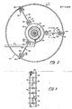
- the expander module is stabilized, as shown in Figs. 1, 2, and 3, by a plurality of at least three vibration damping isolators, preferably ladder isolators 50, disposed symmetrically around the module. Accordingly, the three ladder isolators are situated at 120 * intervals about the periphery of module 12, as depicted in Fig. 2, and hold the expander module in its centered position while cooperating with the bellows to prevent the module from tilting. Inasmuch as the ladder isolators are identical, only one of the ladder isolators is here described.
- Each ladder isolator comprises a pair of sides formed of elongated U-channel members 52.
- One of those members is couplable to the expander module typically by welding or by bolts.
- the other of those U-channel members is couplable, typically by bolts 68 to support member 10 that is secured to and extends down from the vacuum chamber of the electron microscope.
- Connecting the two U-channel members are a plurality of substantially parallel stainless steel stranded wire cables 62 of the type described in military specification MIL-W-83420.
- Each wire cable 62 at its ends is provided with eyelets 60.
- Pins 58 anchored in the U-channels pass through the eyelets of the wire_cables and hold the cables between the two U-channel members.
- cables 62 may be placed in tension.
- the cables are made of strands of stainless steel which are spirally wrapped so that damping of vibrations is provided by rubbing and sliding friction between the strands.
- the ladder isolator has eight cables, each of about 3" in length and about 1/16" in diameter. It is preferred to use as little tension as possible on the cables consistent with holding the expander module centered under operating conditions. It has been found by experience that vibrations tend to be transmitted by the cable when the cable tension is increased to too large an extent.
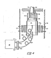
- Fig. 4 the arrangement depicted in Fig. 4 can be employed.
- magnetic isolators are employed to stabilize the expander module.
- Magnetic ring 73 is attached to the expander module.
- the external face of the ring is of one magnetic polarity, while the inner face is of the-opposite magnetic polarity.
- Attached to support 10 extending down from the electron microscope are three bar magnets 77 spaced at 120° intervals around the ring.
- the poles of the bar magnets facing the ring are of the same magnetic polarity as the external face of the ring so that the ring is repelled by the magnetic fields of the bar magnets.
- the bar magnets are equidistant from the ring, the repulsion forces acting on the ring tend to elastically maintain the expander module in its centered position.
- the bar magnets are elongated in the vertical direction. Consequently up and down movement of the expander module does not affect the centering action of the magnetic isolators.
- a magnetic shield can be employed to confine the stray magnetic fields.
- the expander module is usually at the lowest part of the column so that the magnetic fields of the ring and bar magnets should not materially affect the electron beam.
- the compressor furnishes cooled gaseous helium at high pressure through feed line 14 to expander module 12; the helium, after expansion, is returned through low pressure return line 18 to compressor 16. It has been found that the feed and return lines tend also to transmit vibrations from the compressor to the expander module.
- couplings 78 and 80 of feed line 14 and return line 18 are repectively preferably anchored externally.
- Flexible hoses 82 and 84 formed of a material, such as nylon, substantially impervious to gaseous helium is interposed between those couplings and the inlet and outlet connections of the expander module.
- each of the flexible hoses are formed as helices and are freely suspended to absorb vibrations.
- the helix has six or seven turns.
Landscapes
- Engineering & Computer Science (AREA)
- General Engineering & Computer Science (AREA)
- Analytical Chemistry (AREA)
- Chemical & Material Sciences (AREA)
- Aviation & Aerospace Engineering (AREA)
- Mechanical Engineering (AREA)
- Physics & Mathematics (AREA)
- Acoustics & Sound (AREA)
- Compressors, Vaccum Pumps And Other Relevant Systems (AREA)
- Containers, Films, And Cooling For Superconductive Devices (AREA)
- Vibration Prevention Devices (AREA)
- Vibration Dampers (AREA)
- Buildings Adapted To Withstand Abnormal External Influences (AREA)
- Golf Clubs (AREA)
Priority Applications (3)
| Application Number | Priority Date | Filing Date | Title |
|---|---|---|---|
| AT82111621T ATE29622T1 (de) | 1982-12-14 | 1982-12-14 | Schwingungsdaempfungsvorrichtung. |
| EP82111621A EP0111032B1 (de) | 1982-12-14 | 1982-12-14 | Schwingungsdämpfungsvorrichtung |
| DE8282111621T DE3277262D1 (en) | 1982-12-14 | 1982-12-14 | Vibration damping arrangement |
Applications Claiming Priority (1)
| Application Number | Priority Date | Filing Date | Title |
|---|---|---|---|
| EP82111621A EP0111032B1 (de) | 1982-12-14 | 1982-12-14 | Schwingungsdämpfungsvorrichtung |
Publications (2)
| Publication Number | Publication Date |
|---|---|
| EP0111032A1 true EP0111032A1 (de) | 1984-06-20 |
| EP0111032B1 EP0111032B1 (de) | 1987-09-09 |
Family
ID=8189403
Family Applications (1)
| Application Number | Title | Priority Date | Filing Date |
|---|---|---|---|
| EP82111621A Expired EP0111032B1 (de) | 1982-12-14 | 1982-12-14 | Schwingungsdämpfungsvorrichtung |
Country Status (3)
| Country | Link |
|---|---|
| EP (1) | EP0111032B1 (de) |
| AT (1) | ATE29622T1 (de) |
| DE (1) | DE3277262D1 (de) |
Cited By (4)
| Publication number | Priority date | Publication date | Assignee | Title |
|---|---|---|---|---|
| NL1017347C2 (nl) * | 2000-02-17 | 2001-09-13 | Lg Electronics Inc | Pulsbuiskoelinrichting. |
| DE102007022121A1 (de) * | 2007-05-11 | 2008-11-13 | Oerlikon Leybold Vacuum Gmbh | Anordnung aus einer Vakuumpumpe und einem Vakuumrezipienten |
| CN107863218A (zh) * | 2017-11-09 | 2018-03-30 | 西安聚能超导磁体科技有限公司 | 一种有效降低制冷机振动的装置及方法 |
| CN108479878A (zh) * | 2018-02-23 | 2018-09-04 | 中国工程物理研究院激光聚变研究中心 | 一种低振动低温测试装置 |
Citations (4)
| Publication number | Priority date | Publication date | Assignee | Title |
|---|---|---|---|---|
| GB1128148A (en) * | 1965-12-27 | 1968-09-25 | Aeroflex Lab Inc | Vibration-damping and load-supporting apparatus |
| US3423614A (en) * | 1966-12-09 | 1969-01-21 | Gen Electric | Inside-out motion damper |
| US3514600A (en) * | 1967-11-20 | 1970-05-26 | Parke Davis & Co | Flexible conduit means for connecting an electron microscope to a vacuum pump |
| EP0019426A1 (de) * | 1979-05-18 | 1980-11-26 | Fujitsu Limited | Anordnung zur Vibrationsisolation in einem Apparat mit einem Vakuumsystem |
-
1982
- 1982-12-14 AT AT82111621T patent/ATE29622T1/de not_active IP Right Cessation
- 1982-12-14 DE DE8282111621T patent/DE3277262D1/de not_active Expired
- 1982-12-14 EP EP82111621A patent/EP0111032B1/de not_active Expired
Patent Citations (4)
| Publication number | Priority date | Publication date | Assignee | Title |
|---|---|---|---|---|
| GB1128148A (en) * | 1965-12-27 | 1968-09-25 | Aeroflex Lab Inc | Vibration-damping and load-supporting apparatus |
| US3423614A (en) * | 1966-12-09 | 1969-01-21 | Gen Electric | Inside-out motion damper |
| US3514600A (en) * | 1967-11-20 | 1970-05-26 | Parke Davis & Co | Flexible conduit means for connecting an electron microscope to a vacuum pump |
| EP0019426A1 (de) * | 1979-05-18 | 1980-11-26 | Fujitsu Limited | Anordnung zur Vibrationsisolation in einem Apparat mit einem Vakuumsystem |
Cited By (6)
| Publication number | Priority date | Publication date | Assignee | Title |
|---|---|---|---|---|
| NL1017347C2 (nl) * | 2000-02-17 | 2001-09-13 | Lg Electronics Inc | Pulsbuiskoelinrichting. |
| US6467276B2 (en) | 2000-02-17 | 2002-10-22 | Lg Electronics Inc. | Pulse tube refrigerator |
| DE102007022121A1 (de) * | 2007-05-11 | 2008-11-13 | Oerlikon Leybold Vacuum Gmbh | Anordnung aus einer Vakuumpumpe und einem Vakuumrezipienten |
| CN107863218A (zh) * | 2017-11-09 | 2018-03-30 | 西安聚能超导磁体科技有限公司 | 一种有效降低制冷机振动的装置及方法 |
| CN107863218B (zh) * | 2017-11-09 | 2024-03-26 | 西安聚能超导磁体科技有限公司 | 一种有效降低制冷机振动的装置及方法 |
| CN108479878A (zh) * | 2018-02-23 | 2018-09-04 | 中国工程物理研究院激光聚变研究中心 | 一种低振动低温测试装置 |
Also Published As
| Publication number | Publication date |
|---|---|
| EP0111032B1 (de) | 1987-09-09 |
| DE3277262D1 (en) | 1987-10-15 |
| ATE29622T1 (de) | 1987-09-15 |
Similar Documents
| Publication | Publication Date | Title |
|---|---|---|
| US4363217A (en) | Vibration damping apparatus | |
| EP0019426B1 (de) | Anordnung zur Vibrationsisolation in einem Apparat mit einem Vakuumsystem | |
| US4539822A (en) | Vibration isolator for cryopump | |
| US20050204754A1 (en) | Vacuum pump damping adapter | |
| EP0864878B1 (de) | Isolierung der Vibrationen und Reduzierung des Lärms von Kryokühlern in der Bilderzeugung durch magnetische Resonanz | |
| KR100851369B1 (ko) | 선형 압축기 | |
| US5056319A (en) | Refrigerator-operated apparatus | |
| US20050229620A1 (en) | Cooling apparatus | |
| JP7761494B2 (ja) | 極低温装置 | |
| US4833899A (en) | Cryopump with vibration isolation | |
| EP0111032A1 (de) | Schwingungsdämpfungsvorrichtung | |
| JPH03500916A (ja) | 低温冷凍機用ヘリウム圧力シール | |
| JP3901217B2 (ja) | 振動隔離低温装置 | |
| KR102700590B1 (ko) | 크라이오펌프 및 극저온냉동기방진구조 | |
| US20030053918A1 (en) | Vacuum pump having mechanism for restraining vibrations | |
| US4835972A (en) | Flex-line vibration isolator and cryopump with vibration isolation | |
| US5176003A (en) | Cryostat | |
| JPH0653035A (ja) | 超電導マグネット | |
| CN110939556B (zh) | 线性压缩机 | |
| JP2009052881A (ja) | 極低温冷却装置 | |
| EP0525182A1 (de) | Dynamisch ausgeglichener kaltkopf einer gifford-mcmahon kälte- maschine | |
| US5376799A (en) | Turbo-pumped scanning electron microscope | |
| JPS59110939A (ja) | 震動吸収機構 | |
| EP4365521A1 (de) | Kryogene vorrichtung | |
| CN207268334U (zh) | 一种耐用型抽真空设备 |
Legal Events
| Date | Code | Title | Description |
|---|---|---|---|
| PUAI | Public reference made under article 153(3) epc to a published international application that has entered the european phase |
Free format text: ORIGINAL CODE: 0009012 |
|
| AK | Designated contracting states |
Designated state(s): AT BE CH DE FR GB IT LI LU NL SE |
|
| 17P | Request for examination filed |
Effective date: 19841219 |
|
| 17Q | First examination report despatched |
Effective date: 19861125 |
|
| GRAA | (expected) grant |
Free format text: ORIGINAL CODE: 0009210 |
|
| ITF | It: translation for a ep patent filed | ||
| AK | Designated contracting states |
Kind code of ref document: B1 Designated state(s): AT BE CH DE FR GB IT LI LU NL SE |
|
| PG25 | Lapsed in a contracting state [announced via postgrant information from national office to epo] |
Ref country code: BE Effective date: 19870909 |
|
| REF | Corresponds to: |
Ref document number: 29622 Country of ref document: AT Date of ref document: 19870915 Kind code of ref document: T |
|
| REF | Corresponds to: |
Ref document number: 3277262 Country of ref document: DE Date of ref document: 19871015 |
|
| ET | Fr: translation filed | ||
| PG25 | Lapsed in a contracting state [announced via postgrant information from national office to epo] |
Ref country code: AT Effective date: 19871214 |
|
| PG25 | Lapsed in a contracting state [announced via postgrant information from national office to epo] |
Ref country code: SE Effective date: 19871215 |
|
| PG25 | Lapsed in a contracting state [announced via postgrant information from national office to epo] |
Ref country code: LU Free format text: LAPSE BECAUSE OF NON-PAYMENT OF DUE FEES Effective date: 19871231 Ref country code: LI Effective date: 19871231 Ref country code: CH Effective date: 19871231 |
|
| BERE | Be: lapsed |
Owner name: VACUUM TECHNOLOGY INC. Effective date: 19871231 |
|
| PG25 | Lapsed in a contracting state [announced via postgrant information from national office to epo] |
Ref country code: NL Effective date: 19880701 |
|
| PLBE | No opposition filed within time limit |
Free format text: ORIGINAL CODE: 0009261 |
|
| STAA | Information on the status of an ep patent application or granted ep patent |
Free format text: STATUS: NO OPPOSITION FILED WITHIN TIME LIMIT |
|
| NLV4 | Nl: lapsed or anulled due to non-payment of the annual fee | ||
| GBPC | Gb: european patent ceased through non-payment of renewal fee | ||
| 26N | No opposition filed | ||
| PG25 | Lapsed in a contracting state [announced via postgrant information from national office to epo] |
Ref country code: FR Free format text: LAPSE BECAUSE OF NON-PAYMENT OF DUE FEES Effective date: 19880831 |
|
| REG | Reference to a national code |
Ref country code: CH Ref legal event code: PL |
|
| PG25 | Lapsed in a contracting state [announced via postgrant information from national office to epo] |
Ref country code: DE Effective date: 19880901 |
|
| REG | Reference to a national code |
Ref country code: FR Ref legal event code: ST |
|
| PG25 | Lapsed in a contracting state [announced via postgrant information from national office to epo] |
Ref country code: GB Free format text: LAPSE BECAUSE OF NON-PAYMENT OF DUE FEES Effective date: 19881122 |
|
| EUG | Se: european patent has lapsed |
Ref document number: 82111621.7 Effective date: 19880913 |