EP0111034A1 - Sicherheitstüranschlag - Google Patents
Sicherheitstüranschlag Download PDFInfo
- Publication number
- EP0111034A1 EP0111034A1 EP82306450A EP82306450A EP0111034A1 EP 0111034 A1 EP0111034 A1 EP 0111034A1 EP 82306450 A EP82306450 A EP 82306450A EP 82306450 A EP82306450 A EP 82306450A EP 0111034 A1 EP0111034 A1 EP 0111034A1
- Authority
- EP
- European Patent Office
- Prior art keywords
- housing
- door
- mounting plate
- security stop
- floor
- Prior art date
- Legal status (The legal status is an assumption and is not a legal conclusion. Google has not performed a legal analysis and makes no representation as to the accuracy of the status listed.)
- Ceased
Links
- 230000000717 retained effect Effects 0.000 claims abstract description 6
- 229910052751 metal Inorganic materials 0.000 claims description 4
- 239000002184 metal Substances 0.000 claims description 4
- 229910001092 metal group alloy Inorganic materials 0.000 claims description 3
- 239000000956 alloy Substances 0.000 claims description 2
- 239000004411 aluminium Substances 0.000 claims description 2
- 229910052782 aluminium Inorganic materials 0.000 claims description 2
- XAGFODPZIPBFFR-UHFFFAOYSA-N aluminium Chemical compound [Al] XAGFODPZIPBFFR-UHFFFAOYSA-N 0.000 claims description 2
- 238000010276 construction Methods 0.000 description 4
- 239000000463 material Substances 0.000 description 3
- 229920003023 plastic Polymers 0.000 description 2
- 239000004033 plastic Substances 0.000 description 2
- 238000009408 flooring Methods 0.000 description 1
- 230000004048 modification Effects 0.000 description 1
- 238000012986 modification Methods 0.000 description 1
- 230000000630 rising effect Effects 0.000 description 1
- 239000010935 stainless steel Substances 0.000 description 1
- 229910001220 stainless steel Inorganic materials 0.000 description 1
Images
Classifications
-
- E—FIXED CONSTRUCTIONS
- E05—LOCKS; KEYS; WINDOW OR DOOR FITTINGS; SAFES
- E05F—DEVICES FOR MOVING WINGS INTO OPEN OR CLOSED POSITION; CHECKS FOR WINGS; WING FITTINGS NOT OTHERWISE PROVIDED FOR, CONCERNED WITH THE FUNCTIONING OF THE WING
- E05F5/00—Braking devices, e.g. checks; Stops; Buffers
- E05F5/06—Buffers or stops limiting opening of swinging wings, e.g. floor or wall stops
-
- E—FIXED CONSTRUCTIONS
- E05—LOCKS; KEYS; WINDOW OR DOOR FITTINGS; SAFES
- E05Y—INDEXING SCHEME ASSOCIATED WITH SUBCLASSES E05D AND E05F, RELATING TO CONSTRUCTION ELEMENTS, ELECTRIC CONTROL, POWER SUPPLY, POWER SIGNAL OR TRANSMISSION, USER INTERFACES, MOUNTING OR COUPLING, DETAILS, ACCESSORIES, AUXILIARY OPERATIONS NOT OTHERWISE PROVIDED FOR, APPLICATION THEREOF
- E05Y2900/00—Application of doors, windows, wings or fittings thereof
- E05Y2900/10—Application of doors, windows, wings or fittings thereof for buildings or parts thereof
- E05Y2900/13—Type of wing
- E05Y2900/132—Doors
Definitions
- This invention relates to a security stop for a door and more particularly relates to a security stop for use behind a door so that when the security stop is activated the door can only be opened slightly.
- An object of the present invention is to provide a security stop for use behind a door which security stop allows the door to be opened only a very short distance and does not allow ready access to the security stop when the door is opened.
- a further object of the present invention is to provide a security stop for a door which offers to the public a useful alternative choice.
- a security stop for placement behind a door, the security stop comprising a substantially vertically extending member movable in a housing between a first position in which the member is retained substantially within the housing and a second position in which the member extendsfrom the housing to a position where it blocks the opening movement of the door, the arrangement being such that, in use, the housing is positioned behind a door in a position such that the door can be opened when the vertically extending member is in its first position and when the vertically extending member is in its second position, the door can only be opened a small distance until the door contacts the vertically extending member.
- a security stop for placement behind a door, the security stop comprising a housing arranged for attachment to or fitment into a floor of a building in a position behind a door, the housing having therein a biasing means which moves a substantially vertically extending member between a first position in which the member is retained substantially within the housing and a second position in which the member extends from the housing to a position where it interrupts an opening movement of the door, the arrangement being such that when the housing is in position and the extending member is in its first position the door can be opened and closed and when the member is in its second position it interrupts the opening movement of the door so that it can only be opened a short distance.
- the housing can include a mounting plate normally positioned flush with the floor immediately behind the door, the mounting plate supporting a locking plate which has an aperture therein through which the vertically extending member can extend, one end of the locking plate being biased in an upward direction to create frictional engagement between the periphery of the aperture and the extending member, the arrangement being such that when the extending member is in its first position it is retained in this position by the frictional engagement between the locking plate and the upper end of the extending member, when the extending member is to be moved to its second position one end of the locking plate is pressed down ward to reduce the frictional engagement and allow the biasing means to move the extending member to its second position.
- the member can have on a lower end thereof, within the housing, a pin which moves in a guide slot formed in the housing, the guide slot has therein a locking portion into which the pin locks when the member is in its first position, the member being released by being rotated around its longitudinal axis to move the pin into alignment with the guide slot so that the member can move to its second position.
- the security stop according to the present invention can be used in any home or business situation.
- the example described herein will be described with reference to its use in a home situation where it is a substitute for a security chain.
- the security stop is positioned in association with a door so that the door can be opened only a short distance when the security stop is activated.
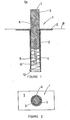
- the security stop is generally indicated by arrow 1 and is mounted so that a mounting plate 2 thereof is flush with a floor or floor covering of the building in which it is used.
- the mounting plate 2 is connected or fixed to a housing 3 which is, in use, positioned in a hole drilled in a concrete floor or positioned in a pipe set in a concrete floor or the mounting plate 2 can be fixed to a flooring material with the housing 3 extending beneath the level of the floor.
- the housing 3 can be constructed from a tubular metal or plastics material which has formed therein a slot or guide 4. .
- the housing 3 has mounted therein a member 5 which has a pin or pins 6 fixed thereto, the pin 6 extending to the side thereof and into the slot 4.
- the pin 6 being arranged to travel in the slot 4 so that the member 5 can move from its retracted or first position substantially within the housing shown dotted in Figure 1 to its extended or second position shown.
- the member 5 In its first position the member 5 has the upper end 7 thereof immediately above the level of the mounting plate 2. This level shown dotted at 8 in Figure 1 would generally be slightly higher or flush with the carpet or floor covering on the floor the level of which is indicated at 9.
- the member 5 In its second position the member 5 is raised to the position shown and this is effected by unlocking-the member from its first position.
- This locking can be effected by providing at a point near the bottom of the slot 4 .
- the locking portion 10 can be an extension of the slot or an angled rebate as shown in Figure 1.
- the member 5 being unlocked by turning same about its longitudinal axis through about ninety degrees to disengage the pin 6 from the locking portion 10.
- the member 5 being forced by a biasing means 11 upwards to its extended position in which the pin 6 is at the top of the slot 4.
- the rear of a door contacts the extended member 5.
- the spring biasing means can be held in position by a locating pin 12 extending transversely through aligned apertures in the housing 2.
- the housing 2 can be constructedfrom aluminium, stainless steel or another metal or metal alloy material.
- the upper end 7 of the member 5 can be provided with a roughened or textured surface so that it can easily be turned to unlock the member 5 from its first position or to lock the member in its first position.
- the security stop according to the present invention is placed in position in the floor or ceiling of a room immediately behind the door so that when it is in its second position it interrupts the opening movement of the door.
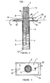
- the alternative construction of security stop shown in Figures 3 and 4 has the parts thereof similar to those incorporated in the example shown in Figures 1 and 2 referenced by the same numerals.
- the mounting plate 2 has supported thereon a locking plate 13.
- the locking plate 13 is preferably constructed from a metal or rigid plastics material and is supported at the end 14 thereof by a pin 15 which extends through holes formed in the locking plate 13 and mounting plate 2.
- the locking plate 13 is biased to its upwards position shown in Figure 3 by providing a biasing means 16 which is positioned between a recess 17 in the mounting plate 2 and the underside of the locking plate 13.
- the locking plate 13 having an aperture 18 therein through which the member 5 extends.
- the diameter of the aperture 18 being slightly larger than the diameter of the extending member 5 and the shape in cross-section is similar to that of the extending member 5.
- the position of the member 5 relative to the mounting plate 2 is governed by the frictional engagement between the periphery of the aperture 18 and the outer surface 19 of the member 5.
- the tension in the biasing means 16 is selected to ensure that the operating pressure on the locking plate is such that it can not accidentally be operated by the weight of an animal or small child.
- a security stop according to the present invention can be fitted to a sliding door by placing same behind the door in the track on which the door slides or in any position in which it interrupts the opening movement of the door.
Landscapes
- Closing And Opening Devices For Wings, And Checks For Wings (AREA)
Priority Applications (1)
| Application Number | Priority Date | Filing Date | Title |
|---|---|---|---|
| EP82306450A EP0111034A1 (de) | 1982-12-03 | 1982-12-03 | Sicherheitstüranschlag |
Applications Claiming Priority (1)
| Application Number | Priority Date | Filing Date | Title |
|---|---|---|---|
| EP82306450A EP0111034A1 (de) | 1982-12-03 | 1982-12-03 | Sicherheitstüranschlag |
Publications (1)
| Publication Number | Publication Date |
|---|---|
| EP0111034A1 true EP0111034A1 (de) | 1984-06-20 |
Family
ID=8189848
Family Applications (1)
| Application Number | Title | Priority Date | Filing Date |
|---|---|---|---|
| EP82306450A Ceased EP0111034A1 (de) | 1982-12-03 | 1982-12-03 | Sicherheitstüranschlag |
Country Status (1)
| Country | Link |
|---|---|
| EP (1) | EP0111034A1 (de) |
Cited By (6)
| Publication number | Priority date | Publication date | Assignee | Title |
|---|---|---|---|---|
| GB2169653A (en) * | 1985-01-16 | 1986-07-16 | Alan Reginald Steele | Door stop arrangement |
| FR2618197A1 (fr) * | 1987-07-15 | 1989-01-20 | Feralco Sa | Amortisseur de choc a retour temporise. |
| US5018241A (en) * | 1989-10-20 | 1991-05-28 | Baines Richard M | Foot-operated door stop assembly |
| US6553617B1 (en) * | 1999-08-09 | 2003-04-29 | Arturo Salice S.P.A. | Braking retardation apparatus for doors, windows or the like |
| GB2432882A (en) * | 2005-11-18 | 2007-06-06 | Anthony Fitzgerald Forde | Retractable security device for limiting the movement of a door |
| EP3088644A1 (de) | 2015-04-28 | 2016-11-02 | Exceptor B.V. | Türstopper- und türsicherheitssystem |
Citations (2)
| Publication number | Priority date | Publication date | Assignee | Title |
|---|---|---|---|---|
| GB898841A (en) * | 1960-06-28 | 1962-06-14 | Mortimer Ernesto Esquivel | A locking device |
| US3330585A (en) * | 1965-04-19 | 1967-07-11 | Pasco Construction Co | Doorstop |
-
1982
- 1982-12-03 EP EP82306450A patent/EP0111034A1/de not_active Ceased
Patent Citations (2)
| Publication number | Priority date | Publication date | Assignee | Title |
|---|---|---|---|---|
| GB898841A (en) * | 1960-06-28 | 1962-06-14 | Mortimer Ernesto Esquivel | A locking device |
| US3330585A (en) * | 1965-04-19 | 1967-07-11 | Pasco Construction Co | Doorstop |
Cited By (6)
| Publication number | Priority date | Publication date | Assignee | Title |
|---|---|---|---|---|
| GB2169653A (en) * | 1985-01-16 | 1986-07-16 | Alan Reginald Steele | Door stop arrangement |
| FR2618197A1 (fr) * | 1987-07-15 | 1989-01-20 | Feralco Sa | Amortisseur de choc a retour temporise. |
| US5018241A (en) * | 1989-10-20 | 1991-05-28 | Baines Richard M | Foot-operated door stop assembly |
| US6553617B1 (en) * | 1999-08-09 | 2003-04-29 | Arturo Salice S.P.A. | Braking retardation apparatus for doors, windows or the like |
| GB2432882A (en) * | 2005-11-18 | 2007-06-06 | Anthony Fitzgerald Forde | Retractable security device for limiting the movement of a door |
| EP3088644A1 (de) | 2015-04-28 | 2016-11-02 | Exceptor B.V. | Türstopper- und türsicherheitssystem |
Similar Documents
| Publication | Publication Date | Title |
|---|---|---|
| US5018241A (en) | Foot-operated door stop assembly | |
| US9279284B1 (en) | Foot operated pet gate | |
| US4343500A (en) | Floor imbedded door bolt | |
| WO1986006781A1 (en) | Door stop assembly | |
| US4746152A (en) | Door lock | |
| US6161252A (en) | Foot released open door holder | |
| US4248461A (en) | Sliding door locking apparatus | |
| US3006676A (en) | Combination door check and stop | |
| GB2548228B (en) | Gate latch | |
| US3637246A (en) | Latching mechanism | |
| US4648638A (en) | Sliding door lock assembly | |
| US5809613A (en) | Foot-operated door stop assembly | |
| US3645572A (en) | Panic bar stiffener | |
| US4759575A (en) | Sliding door lock assembly | |
| EP1048811A1 (de) | System zum Öffnen von Türen | |
| US5492377A (en) | Window lock | |
| US4974887A (en) | Locking device for sliding members | |
| US5671957A (en) | Child resistant tube latch | |
| US6183023B1 (en) | Door with integrated fire exit device | |
| WO1997020122A1 (en) | Lock mechanism device | |
| US4902054A (en) | Safety device for disabling a screen door latching mechanism | |
| US5713227A (en) | Lever activated dead-bolt lock | |
| NZ190814A (en) | Door stop | |
| JPH063925Y2 (ja) | 落し錠 | |
| JPH119345A (ja) | 家具等の天板昇降装置 |
Legal Events
| Date | Code | Title | Description |
|---|---|---|---|
| PUAI | Public reference made under article 153(3) epc to a published international application that has entered the european phase |
Free format text: ORIGINAL CODE: 0009012 |
|
| AK | Designated contracting states |
Designated state(s): AT BE CH DE FR GB IT LI LU NL SE |
|
| 17P | Request for examination filed |
Effective date: 19841213 |
|
| STAA | Information on the status of an ep patent application or granted ep patent |
Free format text: STATUS: THE APPLICATION HAS BEEN REFUSED |
|
| 18R | Application refused |
Effective date: 19870606 |