EP0111233B1 - Fermeture à glissière en courbe et son procédé de fabrication - Google Patents
Fermeture à glissière en courbe et son procédé de fabrication Download PDFInfo
- Publication number
- EP0111233B1 EP0111233B1 EP83111872A EP83111872A EP0111233B1 EP 0111233 B1 EP0111233 B1 EP 0111233B1 EP 83111872 A EP83111872 A EP 83111872A EP 83111872 A EP83111872 A EP 83111872A EP 0111233 B1 EP0111233 B1 EP 0111233B1
- Authority
- EP
- European Patent Office
- Prior art keywords
- inter
- fastener
- curved
- pair
- stringers
- Prior art date
- Legal status (The legal status is an assumption and is not a legal conclusion. Google has not performed a legal analysis and makes no representation as to the accuracy of the status listed.)
- Expired
Links
Images


Classifications
-
- A—HUMAN NECESSITIES
- A44—HABERDASHERY; JEWELLERY
- A44B—BUTTONS, PINS, BUCKLES, SLIDE FASTENERS, OR THE LIKE
- A44B19/00—Slide fasteners
-
- A—HUMAN NECESSITIES
- A44—HABERDASHERY; JEWELLERY
- A44B—BUTTONS, PINS, BUCKLES, SLIDE FASTENERS, OR THE LIKE
- A44B19/00—Slide fasteners
- A44B19/24—Details
- A44B19/34—Stringer tapes; Flaps secured to stringers for covering the interlocking members
-
- A—HUMAN NECESSITIES
- A44—HABERDASHERY; JEWELLERY
- A44B—BUTTONS, PINS, BUCKLES, SLIDE FASTENERS, OR THE LIKE
- A44B19/00—Slide fasteners
- A44B19/24—Details
- A44B19/40—Connection of separate, or one-piece, interlocking members to stringer tapes; Reinforcing such connections, e.g. by stitching
- A44B19/403—Connection of separate interlocking members
-
- A—HUMAN NECESSITIES
- A44—HABERDASHERY; JEWELLERY
- A44B—BUTTONS, PINS, BUCKLES, SLIDE FASTENERS, OR THE LIKE
- A44B19/00—Slide fasteners
- A44B19/42—Making by processes not fully provided for in one other class, e.g. B21D53/50, B21F45/18, B22D17/16, B29D5/00
-
- Y—GENERAL TAGGING OF NEW TECHNOLOGICAL DEVELOPMENTS; GENERAL TAGGING OF CROSS-SECTIONAL TECHNOLOGIES SPANNING OVER SEVERAL SECTIONS OF THE IPC; TECHNICAL SUBJECTS COVERED BY FORMER USPC CROSS-REFERENCE ART COLLECTIONS [XRACs] AND DIGESTS
- Y10—TECHNICAL SUBJECTS COVERED BY FORMER USPC
- Y10T—TECHNICAL SUBJECTS COVERED BY FORMER US CLASSIFICATION
- Y10T29/00—Metal working
- Y10T29/49—Method of mechanical manufacture
- Y10T29/49782—Method of mechanical manufacture of a slide fastener
Definitions
- This invention generally relates to a method for producing a curved slide fastener, and more particularly a curved slide fastener chain from which curved slide fasteners are formed and a curved slide fastener obtained by such method.
- Straight slide fasteners having no curved portion therein are produced by the method including the steps of:
- a curved slide fastener In contrast with the aforementioned straight slide fastener, a curved slide fastener, to which this invention is directed, has a curved portion therein, so that difficulties arise in producing a curved slide fastener according to the aforementioned method for producing straight slide fasteners.
- a curved slide fastener F comprises a pair of fastener stringers 1 and 2, a bottom stop 14, two upper stops 16, and a slider 15.
- Each of the fastener stringers includes a fastener tape 3 (or 4) and a fastener element row 5 (or 6) formed by planting fastener elements on the inner side edge of the fastener tape 3 (or 4).
- Each fastener element row 5 (or 6) has a straight inter-engagement portion 9 (or 10) and a curved inter-engagement portion 11 (or 12).
- the element pitches P1 and P2 in the straight inter-engagement portions 9 and 10, respectively, are identical to one another, while the element pitches P3 and P4 in the curved inter-engagement portions 11 and 12, respectively, are different to one another.
- the element pitch P4 is larger than the element pitch P3, so that the curved inter-engagement portions 11 and 12, when inter-engaged together, represent a curved line in the plane in which the line represented by the straight inter-engagement portions 9 and 10 extends.
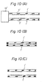
- the element pitches P1' and P2' in the straight portions 9' and 10', respectively, are identical to one another, while the element pitches P3' and P4' in the curved portions 11' and 12', respectively, are different to one another.
- the pitch P4' is larger than the pitch P3' so that, when the element rows 5' and 6' facing one another are inter-engaged together, the curved portions 11' and 12' curve downwardly in the drawing.
- curved slide fasteners are conventionally produced by the method including the steps of:
- curved slide fastener chains are usually stored in cylindrical vessel or reeled around a reel so as to facilitate transportation thereof, the curved inter-engagement portion thereof tends to be extended by tensile force continuously applied to the fastener chains.
- an object of the present invention to overcome the disadvantages in the prior art curved slide fastener chain by providing a curved slide fastener chain having curved inter-engagement portions which do not deform even when subjected to the tension applied thereto during the production process and transportation of the curved slide fastener chain.
- the method of the present invention is adapted for producing a curved slide fastener chain comprising a pair of fastener tapes each of which includes a plurality of groups of elements arranged in rows disposed in series and spaced relation thereon, each element row having a straight inter-engagement portion and a curved inter-engagement portion, the element pitch in the curved inter-engagement portion of one of a pair of fastener tapes being larger than the element pitch in the curved inter-engagement portion of the other of the pair of fastener tapes.
- a pair of fastener stringers are formed simultaneously, each curved inter-engaging portion of one of said fastener stringers having an element pitch larger than that of the curved inter-engagement portion of the other of said fastener stringers, and the distance between the first effective element of one group of elements and the first effective element of the group of elements succeeding said one group is substantially identical in both fastener stringers. Subsequently the pair of fastener stringers are inter-engaged so that said curved inter-engagement portions remain at least partly not inter-engaged and said straight inter-engagement portions are at least partly inter-engaged, to form the desired slide fastener chain.
- a method for producing a curved slide fastener comprises a step of forming a pair of fastener stringers by planting a plurality of element rows on each of a pair of fastener tapes in series and spaced relation and with different element pitches, so that each curved inter-engagement portion of one of the pair of fastener stringers has an element pitch larger than that in the curved inter-engagement portion of the other of the pair of fastener stringers; a step of partially inter-engaging a pair of fastener stringers to form a fastener chain, a step of washing, dewatering and drying the fastener chain while applying tension thereto; and a step of forming slide fasteners by cutting the slide fastener chain into a unit length after applying parts, such as sliders, to the fastener chain.
- the pair of fastener stringers are formed simultaneously and so that the distance between the first elements in the respective element rows disposed adjacent to one another is substantially constant.
- a pair of fastener stringers are inter-engaged to form a fastener chain in which at least most of the curved inter-engagement portions is dis-inter-engaged and is thereafter supplied to the succeeding step of washing, dewatering and drying the fastener chain where the fastener chain is processed with at least most of the curved inter-engagement portion thereof being dis-inter-engaged.
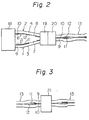
- Fig. 2 shows a step of forming a pair of fastener stringers 1 and 2 and a step of inter-engaging the fastener stringers to form a fastener chain
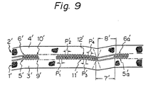
- Fig. 3 shows the steps of washing, dewatering and drying the fastener chain while applying tension thereto
- Fig. 4 and Fig. 5 show a step of forming a curved slide fastener by cutting the fastener chain into a unit length after applying thereto bottom stops 14, sliders 15 and upper stops 16.
- a pair of fastener stringers 1 and 2 are forming by planting fastener elements on a pair of fastener tapes 3 and 4.
- the planting of the elements on a pair of fastener tapes is so performed that element rows 5 and 6 are disposed on the respective inner edge of a pair of the fastener tapes in series and spaced relation.
- each of the element rows 5 and 6 have a straight inter-engagement portion 9 or 10 and a curved inter-engagement portion 11 or 12 next to the straight portion.
- the element pitches P1 and P2 in the straight portions 9 and 10, respectively, are identical to one another, while the element pitches P3 and P4 are not identical to each other.
- the curved portions 11 and 12 are so formed that the element pitch P4 is larger than the element pitch P3.
- relation between the pitch P3 and pitch P4 relative to one another may optionally be selected depending upon the expected configuration of a curved portion.
- the element rows 5 and 6 are formed on the respective fastener tapes 3 and 4, so that the distance L1 [measured from the first element (a) of the element row 5 to the first element (c) of an element row 5a next to the row 5] and the distance L2 [measured from the first element (b) of the element row 6 to the first element (d) of an element row 6a next to the row 6] are identical to one another.
- the spaces 7 and 8 formed between the element rows 5 and 5a and the element rows 6 and 6a, respectively, are not of the same length, since the distances L1 and L2 mentioned above are identical to one another.
- fastener stringers 1 and 2b which form a curved slide fastener having only one upper stop 16 applied to the fastener stringer 1b, are shown.
- fastener element row 6b' which is next to the element row 6b has additional non-inter-engagement elements 17 disposed at the position opposite to the upper stop 16, while the fastener stringers 1 and 2 illustrated in Fig. 6 are both formed with their respective upper stops (not shown).
- the lengths of element rows, on opposite heads are not the same.
- the distances L1 and L2 correspond to the measurement of the respective gaps between their effective elements to be inter-engaged.
- a pair of fastener stringers 1 and 2 formed in the preceding step are inter-engaged together over the entire length of each of the element rows 5 and 6 by means of an inter-engaging device 19 and thereafter the curved inter-engagement portions 11 and 12 are dis-inter-engaged by means of a dis-inter-engaging device 20.
- a fastener chain 13 having straight inter-engagement portions which are inter-engaged and curved inter-engagement portions which are dis-inter-engaged is formed.
- the fastener chain 13 having dis-inter-engaged curved inter-engagement portions can be formed by inter-engaging only the straight inter-engagement portions 9 and 10.
- the curved inter-engagement portions are shown to be inter-engaged over their entire length in the embodiment shown in Fig. 2, the curved inter-engagement portions may be partly inter-engaged, provided that the greater part thereof is dis-inter-engaged.
- the dis-inter-engagement portion it is also permissible for the dis-inter-engagement portion to extend slightly into the straight portions.
- the fastener chain having dis-inter-engaged curved portions is supplied to a washing, dewatering and drying unit 21 shown in Fig. 8.
- the fastener chain 13 is washed in a water vessel containing washing liquid 24 by means of a first roll brush 23 and thereafter is cleaned in a reservoir 22 containing water 26 by means of a second roll brush 25.
- the fastener chain 13 is dewatered by passing through a dewatering device 27 of vacuum type. Then the fastener chain 13 is dried and ironed on a plurality of tension rollers 29 in thermal drying equipment 28.
- the washing, dewatering and drying step described above is an important step which is conventionally applied to the fastener chain in order to remove impurities, such as powdered shavings from the element material, machine oil and smudge, adhered to the fastener chain and also to stabilize quality of the fastener chain.
- bottom stops 14 are attached to the fastener chain by means of a bottom stop applying device 32. Since it is required that all the inter-engagement portions including straight and curved portions of the fastener chain brought from the preceding step are completely inter-engaged in order to achieve the attachment of the bottom stops 14, all the inter-engagement portions are inter-engaged by means of an inter-engaging device 31 after all the inter-engagement portions have been once dis-inter-engaged over their entire length by a dis-inter-engaging device 30 and thereafter the bottom stops 14 are attached to the fastener chain 13. Subsequently, as shown in Fig.
- sliders 15 are attached to the inter-engaged fastener chain 13 through the spaces 7 and 8 and thereafter upper stops 16 are applied to the fastener chain by means of a finishing device 33. Finally, the fastener chain 13 is cut at the intermediate portion of each of the spaces 7 and 8 to form the desired curved slide fasteners.
- a curved slide fastener chain having curved inter-engagement portions each of which is dis-inter-engaged is provided. Because of the dis-inter-engaged configuration of the curved inter-engagement portions, both of a pair of fastener stringers are able to extend in a straight line, so that there is no need to process a pair of fastener stringers individually or separately in the step of washing, dewatering and drying the fastener chain where curved portions tend to deform easily because of heat and tension.
Landscapes
- Slide Fasteners (AREA)
Claims (2)
caractérisé en ce que:
Applications Claiming Priority (4)
| Application Number | Priority Date | Filing Date | Title |
|---|---|---|---|
| JP21302082A JPS59103607A (ja) | 1982-12-03 | 1982-12-03 | 曲りスライドフアスナ−の製造方法 |
| JP213020/82 | 1982-12-03 | ||
| JP19080782U JPS5993207U (ja) | 1982-12-16 | 1982-12-16 | 曲りスライドフアスナ−チエ−ン |
| JP190807/82U | 1982-12-16 |
Publications (2)
| Publication Number | Publication Date |
|---|---|
| EP0111233A1 EP0111233A1 (fr) | 1984-06-20 |
| EP0111233B1 true EP0111233B1 (fr) | 1988-01-07 |
Family
ID=26506324
Family Applications (1)
| Application Number | Title | Priority Date | Filing Date |
|---|---|---|---|
| EP83111872A Expired EP0111233B1 (fr) | 1982-12-03 | 1983-11-28 | Fermeture à glissière en courbe et son procédé de fabrication |
Country Status (12)
| Country | Link |
|---|---|
| US (1) | US4607425A (fr) |
| EP (1) | EP0111233B1 (fr) |
| KR (1) | KR850001463B1 (fr) |
| AU (1) | AU554886B2 (fr) |
| BR (1) | BR8306669A (fr) |
| CA (1) | CA1226723A (fr) |
| DE (2) | DE111233T1 (fr) |
| ES (1) | ES8500027A1 (fr) |
| GB (1) | GB2132689B (fr) |
| HK (1) | HK93488A (fr) |
| MY (1) | MY8800032A (fr) |
| SG (1) | SG83187G (fr) |
Cited By (1)
| Publication number | Priority date | Publication date | Assignee | Title |
|---|---|---|---|---|
| DE102021103425B3 (de) | 2021-02-14 | 2021-11-04 | Constanze Elmdust | Stiefel mit einem Schuhteil und einem mittels eines teilbaren Reißverschlusses abtrennbaren Schaftteil sowie dazugehöriger Reißverschluss |
Families Citing this family (8)
| Publication number | Priority date | Publication date | Assignee | Title |
|---|---|---|---|---|
| JPH0759205B2 (ja) * | 1988-10-14 | 1995-06-28 | ワイケイケイ株式会社 | 曲りスライドファスナーチェーン及び曲りスライドファスナーの製造方法 |
| GB2332020A (en) * | 1997-12-03 | 1999-06-09 | Ykk Europ Ltd | Cleaning zip fastener |
| USD513715S1 (en) | 2001-01-24 | 2006-01-24 | Arc Teryx Equipment Inc. | Curvilinear zipper |
| EP1357814A1 (fr) * | 2001-01-24 | 2003-11-05 | Arc'Teryx Equipment Inc. | Veste a capuche reglable |
| ITGE20040104A1 (it) * | 2004-11-12 | 2005-02-12 | Mattia Basso | Metodo di preparazione di prodotti e confezioni, generalmente per l'abbigliamento, ottenuti tramite nastro a doppie zips laterali esterne. |
| CN110300525B (zh) * | 2017-02-15 | 2022-04-15 | Ykk株式会社 | 拉链链条的矫正装置和矫正方法 |
| US11363860B2 (en) * | 2019-11-23 | 2022-06-21 | Talon Technologies, Inc. | Waterproof curved zippers |
| EP3842589B1 (fr) * | 2019-12-27 | 2025-07-23 | YKK Corporation | Procédé de fabrication d'une fermeture à glissière et fermeture à glissière |
Family Cites Families (13)
| Publication number | Priority date | Publication date | Assignee | Title |
|---|---|---|---|---|
| GB133729A (fr) * | ||||
| GB113099A (en) * | 1917-01-30 | 1919-06-26 | Gideon Sundback | Improvements in Curtains, Coverings or the like especially suitable for Vehicles. |
| GB464575A (en) * | 1936-11-27 | 1937-04-20 | Franz Schatzky | Curved sliding clasp fastener |
| US2511414A (en) * | 1946-09-05 | 1950-06-13 | Talon Inc | Slide fastener |
| US2623214A (en) * | 1948-08-21 | 1952-12-30 | Acme Slide Fastener Co Ltd | Method of applying slide fasteners |
| US2697227A (en) * | 1950-11-14 | 1954-12-21 | Conmar Prod Corp | Slide fastener |
| GB742045A (en) * | 1953-12-01 | 1955-12-21 | Aero Zipp Fasteners Ltd | Improvements in or relating to sliding clasp fasteners |
| GB811653A (en) * | 1955-05-19 | 1959-04-08 | Goodrich Co B F | Sealing slide fasteners and method of and apparatus for making the same |
| GB1129368A (en) * | 1965-11-23 | 1968-10-02 | Opti Holding Ag | Improvements in or relating to sliding clasp fasteners |
| DE2101627A1 (en) * | 1971-01-14 | 1972-07-27 | Kleiber & Co, 8998 Lindenberg | Plastic pressure fastening band - for fabric or plastic garments or articles having mating surface strips |
| US3717908A (en) * | 1971-03-31 | 1973-02-27 | American Velcro Inc | Deformable fastening device |
| CA1068477A (fr) * | 1975-08-27 | 1979-12-25 | Haeng Y. Lee | Attache a glissiere a trois voies |
| US4254538A (en) * | 1976-10-29 | 1981-03-10 | Textron, Inc. | Slide fastener installation and method of making the same |
-
1983
- 1983-11-24 AU AU21646/83A patent/AU554886B2/en not_active Ceased
- 1983-11-28 DE DE198383111872T patent/DE111233T1/de active Pending
- 1983-11-28 DE DE8383111872T patent/DE3375064D1/de not_active Expired
- 1983-11-28 EP EP83111872A patent/EP0111233B1/fr not_active Expired
- 1983-11-29 US US06/556,094 patent/US4607425A/en not_active Expired - Fee Related
- 1983-11-30 BR BR8306669A patent/BR8306669A/pt not_active IP Right Cessation
- 1983-12-02 GB GB08332310A patent/GB2132689B/en not_active Expired
- 1983-12-02 ES ES528185A patent/ES8500027A1/es not_active Expired
- 1983-12-02 KR KR1019830005706A patent/KR850001463B1/ko not_active Expired
- 1983-12-02 CA CA000442462A patent/CA1226723A/fr not_active Expired
-
1987
- 1987-10-12 SG SG831/87A patent/SG83187G/en unknown
-
1988
- 1988-11-17 HK HK934/88A patent/HK93488A/xx unknown
- 1988-12-30 MY MY32/88A patent/MY8800032A/xx unknown
Cited By (2)
| Publication number | Priority date | Publication date | Assignee | Title |
|---|---|---|---|---|
| DE102021103425B3 (de) | 2021-02-14 | 2021-11-04 | Constanze Elmdust | Stiefel mit einem Schuhteil und einem mittels eines teilbaren Reißverschlusses abtrennbaren Schaftteil sowie dazugehöriger Reißverschluss |
| WO2022171848A1 (fr) | 2021-02-14 | 2022-08-18 | Constanze Elmdust | Botte dotée d'une partie de chaussure et d'une partie de tige qui peuvent être découplées au moyen d'une fermeture à glissière séparable, et fermeture à glissière associée |
Also Published As
| Publication number | Publication date |
|---|---|
| DE3375064D1 (en) | 1988-02-11 |
| DE111233T1 (de) | 1984-10-11 |
| ES528185A0 (es) | 1984-11-01 |
| GB2132689A (en) | 1984-07-11 |
| KR850001463B1 (ko) | 1985-10-10 |
| HK93488A (en) | 1988-11-25 |
| ES8500027A1 (es) | 1984-11-01 |
| US4607425A (en) | 1986-08-26 |
| GB2132689B (en) | 1986-06-18 |
| SG83187G (en) | 1988-04-15 |
| EP0111233A1 (fr) | 1984-06-20 |
| MY8800032A (en) | 1988-12-31 |
| GB8332310D0 (en) | 1984-01-11 |
| CA1226723A (fr) | 1987-09-15 |
| AU554886B2 (en) | 1986-09-04 |
| AU2164683A (en) | 1984-06-07 |
| KR840007068A (ko) | 1984-12-05 |
| BR8306669A (pt) | 1984-07-17 |
Similar Documents
| Publication | Publication Date | Title |
|---|---|---|
| DE112010005805B4 (de) | Reißverschluss und Verfahren zum Herstellen desselben | |
| EP0111233B1 (fr) | Fermeture à glissière en courbe et son procédé de fabrication | |
| DE69006431T2 (de) | Tragband für eine Langspaltpresse. | |
| DE2436125B2 (de) | Verfahren und vorrichtung zur herstellung von haken oder oesen tragenden verschlussteilen | |
| EP0116894B1 (fr) | Procédé de fabrication d'une bande de tamisage fabriquée avec spirales | |
| US4845829A (en) | Method of manufacturing separable slide fastener | |
| DE69804184T2 (de) | Trägerband für elektronische Bauteile | |
| DE69306882T2 (de) | Verfahren zur Erzeugung von Lücken in einer Reissverschlusskette | |
| KR860002987A (ko) | 분리 가능한 슬라이드 파스너의 제조방법 | |
| DE19847345B4 (de) | Verfahren und Anlage zur Herstellung von endlosen Furnierschichtplatten | |
| DE69012456T2 (de) | Supraleiter mit einer Vielzahl von umgesetzten Fasern und mit inneren Kühlkanälen und Verfahren zu dessen Herstellung. | |
| DE2703147C2 (de) | Verfahren zum Verbinden zweier Bandenden und dieses Verfahren anwendendes Band | |
| DE102023117152A1 (de) | REIßVERSCHLUSS UND VERFAHREN ZUR HERSTELLUNG EINER WASSERDICHTEN REIßVERSCHLUSSKETTE | |
| US2969029A (en) | Method of producing continuous stringer workpieces with continuous covering members thereon | |
| US5043125A (en) | Method of forming a chain of meandering coupling elements for slide fasteners | |
| US2264325A (en) | Method of making separable fasteners | |
| DE102013202043B4 (de) | Verfahren zur Herstellung eines Hakenelements eines Klettverschlusses und durch das Verfahren hergestelltes Hakenelement | |
| DE3033743A1 (de) | Gewebte reissverschlusshaelfte | |
| US3114967A (en) | Method of making a slide fastener | |
| JPS6346681B2 (fr) | ||
| DE3925835C2 (fr) | ||
| HK34687A (en) | Slide fastener stringer | |
| DE102025101553A1 (de) | Flüssigkeitsundurchlässiger spiralreissverschluss und kommerzielles produkt mit demselben | |
| DE2841630A1 (de) | Gewebte reissverschlusskette und verfahren zu deren herstellung | |
| DE102024114392A1 (de) | Spulenförmiger flüssigkeitsundurchlässiger reissverschluss und ein damit ausgestattetes kommerzielles produkt |
Legal Events
| Date | Code | Title | Description |
|---|---|---|---|
| PUAI | Public reference made under article 153(3) epc to a published international application that has entered the european phase |
Free format text: ORIGINAL CODE: 0009012 |
|
| AK | Designated contracting states |
Kind code of ref document: A1 Designated state(s): BE DE FR IT NL |
|
| EL | Fr: translation of claims filed | ||
| TCNL | Nl: translation of patent claims filed | ||
| ITCL | It: translation for ep claims filed |
Representative=s name: JACOBACCI CASETTA & PERANI S.P.A. |
|
| DET | De: translation of patent claims | ||
| 17P | Request for examination filed |
Effective date: 19840905 |
|
| GRAA | (expected) grant |
Free format text: ORIGINAL CODE: 0009210 |
|
| AK | Designated contracting states |
Kind code of ref document: B1 Designated state(s): BE DE FR IT NL |
|
| ITF | It: translation for a ep patent filed | ||
| REF | Corresponds to: |
Ref document number: 3375064 Country of ref document: DE Date of ref document: 19880211 |
|
| ET | Fr: translation filed | ||
| PLBE | No opposition filed within time limit |
Free format text: ORIGINAL CODE: 0009261 |
|
| STAA | Information on the status of an ep patent application or granted ep patent |
Free format text: STATUS: NO OPPOSITION FILED WITHIN TIME LIMIT |
|
| 26N | No opposition filed | ||
| ITTA | It: last paid annual fee | ||
| PGFP | Annual fee paid to national office [announced via postgrant information from national office to epo] |
Ref country code: DE Payment date: 19931129 Year of fee payment: 11 |
|
| PGFP | Annual fee paid to national office [announced via postgrant information from national office to epo] |
Ref country code: NL Payment date: 19931130 Year of fee payment: 11 |
|
| PGFP | Annual fee paid to national office [announced via postgrant information from national office to epo] |
Ref country code: BE Payment date: 19940810 Year of fee payment: 12 |
|
| PGFP | Annual fee paid to national office [announced via postgrant information from national office to epo] |
Ref country code: FR Payment date: 19940923 Year of fee payment: 12 |
|
| PG25 | Lapsed in a contracting state [announced via postgrant information from national office to epo] |
Ref country code: NL Effective date: 19950601 |
|
| NLV4 | Nl: lapsed or anulled due to non-payment of the annual fee | ||
| PG25 | Lapsed in a contracting state [announced via postgrant information from national office to epo] |
Ref country code: DE Effective date: 19950801 |
|
| PG25 | Lapsed in a contracting state [announced via postgrant information from national office to epo] |
Ref country code: BE Effective date: 19951130 |
|
| BERE | Be: lapsed |
Owner name: YOSHIDA KOGYO K.K. Effective date: 19951130 |
|
| PG25 | Lapsed in a contracting state [announced via postgrant information from national office to epo] |
Ref country code: FR Effective date: 19960731 |
|
| REG | Reference to a national code |
Ref country code: FR Ref legal event code: ST |