EP0111322B1 - Machine de traitement du courrier électronique - Google Patents
Machine de traitement du courrier électronique Download PDFInfo
- Publication number
- EP0111322B1 EP0111322B1 EP83112364A EP83112364A EP0111322B1 EP 0111322 B1 EP0111322 B1 EP 0111322B1 EP 83112364 A EP83112364 A EP 83112364A EP 83112364 A EP83112364 A EP 83112364A EP 0111322 B1 EP0111322 B1 EP 0111322B1
- Authority
- EP
- European Patent Office
- Prior art keywords
- microprocessor
- platen
- clutch
- housing
- mailing machine
- Prior art date
- Legal status (The legal status is an assumption and is not a legal conclusion. Google has not performed a legal analysis and makes no representation as to the accuracy of the status listed.)
- Expired - Lifetime
Links
- 230000015654 memory Effects 0.000 claims abstract description 30
- 230000000694 effects Effects 0.000 claims abstract description 7
- 230000033001 locomotion Effects 0.000 claims description 14
- 230000001174 ascending effect Effects 0.000 claims description 11
- 230000011664 signaling Effects 0.000 claims description 8
- 230000008859 change Effects 0.000 claims description 5
- 230000004044 response Effects 0.000 claims 2
- 230000008878 coupling Effects 0.000 claims 1
- 238000010168 coupling process Methods 0.000 claims 1
- 238000005859 coupling reaction Methods 0.000 claims 1
- 230000001419 dependent effect Effects 0.000 claims 1
- 230000007246 mechanism Effects 0.000 abstract description 14
- 238000012545 processing Methods 0.000 abstract description 3
- 230000003287 optical effect Effects 0.000 description 16
- 238000005266 casting Methods 0.000 description 6
- 230000006870 function Effects 0.000 description 6
- 230000003068 static effect Effects 0.000 description 4
- 210000003813 thumb Anatomy 0.000 description 4
- 238000004891 communication Methods 0.000 description 3
- 150000001875 compounds Chemical class 0.000 description 3
- 210000003811 finger Anatomy 0.000 description 3
- 230000003993 interaction Effects 0.000 description 3
- 238000013475 authorization Methods 0.000 description 2
- 238000010276 construction Methods 0.000 description 2
- 230000000994 depressogenic effect Effects 0.000 description 2
- 238000010586 diagram Methods 0.000 description 2
- 229920001821 foam rubber Polymers 0.000 description 2
- 230000000717 retained effect Effects 0.000 description 2
- 230000009471 action Effects 0.000 description 1
- 238000013459 approach Methods 0.000 description 1
- 230000003190 augmentative effect Effects 0.000 description 1
- 230000008901 benefit Effects 0.000 description 1
- 238000012790 confirmation Methods 0.000 description 1
- 230000000881 depressing effect Effects 0.000 description 1
- 238000006073 displacement reaction Methods 0.000 description 1
- 230000005662 electromechanics Effects 0.000 description 1
- 238000007689 inspection Methods 0.000 description 1
- 230000001788 irregular Effects 0.000 description 1
- 239000012528 membrane Substances 0.000 description 1
- 230000007935 neutral effect Effects 0.000 description 1
- 230000000284 resting effect Effects 0.000 description 1
- 239000004065 semiconductor Substances 0.000 description 1
- 238000012546 transfer Methods 0.000 description 1
- 230000001052 transient effect Effects 0.000 description 1
- 238000011144 upstream manufacturing Methods 0.000 description 1
Images






Classifications
-
- G—PHYSICS
- G07—CHECKING-DEVICES
- G07B—TICKET-ISSUING APPARATUS; FARE-REGISTERING APPARATUS; FRANKING APPARATUS
- G07B17/00—Franking apparatus
- G07B17/00185—Details internally of apparatus in a franking system, e.g. franking machine at customer or apparatus at post office
- G07B17/00193—Constructional details of apparatus in a franking system
-
- G—PHYSICS
- G07—CHECKING-DEVICES
- G07B—TICKET-ISSUING APPARATUS; FARE-REGISTERING APPARATUS; FRANKING APPARATUS
- G07B17/00—Franking apparatus
- G07B17/00459—Details relating to mailpieces in a franking system
- G07B17/00467—Transporting mailpieces
-
- G—PHYSICS
- G07—CHECKING-DEVICES
- G07B—TICKET-ISSUING APPARATUS; FARE-REGISTERING APPARATUS; FRANKING APPARATUS
- G07B17/00—Franking apparatus
- G07B17/00185—Details internally of apparatus in a franking system, e.g. franking machine at customer or apparatus at post office
- G07B17/00193—Constructional details of apparatus in a franking system
- G07B2017/00233—Housing, e.g. lock or hardened casing
-
- G—PHYSICS
- G07—CHECKING-DEVICES
- G07B—TICKET-ISSUING APPARATUS; FARE-REGISTERING APPARATUS; FRANKING APPARATUS
- G07B17/00—Franking apparatus
- G07B17/00459—Details relating to mailpieces in a franking system
- G07B17/00661—Sensing or measuring mailpieces
- G07B2017/00685—Measuring the dimensions of mailpieces
Definitions
- the present invention relates to electronic mailing machines.
- the postage meter Since the first postage meter was invented by Mr Arthur H. Pitney at the turn of the century, the postage meter has had a rather steady evolution until the late 1970's. During this long period, the postage meter was basically a mechanical device involving a printing means with ascending and descending registers. The meter could be charged with a fixed amount of postage and there could be accounting of the amount of postage that had been used as well as a record of the amount of postage remaining. What is commonly referred to as a postage meter is actually two separate units, the postage meter and drive means therefor which is referred to as the base. Although the base is also referred to as the mailing machine, as used in this specification the term mailing machine includes the postage meter and drive means therefor.
- the postage meter is that portion of the device that has the printing dies as well as the ascending and descending registers.
- the base is that portion of the device that supplies drive to the postage meter portion. The reason for having made this device in two separable units was because the postage meter portion had to be brought to a post office periodically in order to have more postage charged to such meter. It obviously would be less of a task to carry out postage meter portion of the machine without having to bring the drive portion as well. For this reason, the heavier parts of the machine were located in the base.
- An electronic postage meter is known from US-A-3 978 457.
- This meter comprises a housing having a slot for receiving a mailpiece.
- a keyboard is provided for entry of data, and a microprocessor controls accounting and printing operations of the system. Printing of postage is effected by a rotatable platen and a signal is sent to the microprocessor to indicate completion of a printing cycle.
- a mechanical mailing machine (in the general sense) is known from UA-A-3 693 543.
- This comprises a housing having a slot for receiving envelopes, a movable platen supported in the housing for moving into and out of the slot, a print head within the housing and spaced from and addressing the platen, a switch, and means in the housing for moving the platen toward and away from the print head upon actuation of the switch.
- the machine is not in any sense electronic and in fact is not a true postage meter because it comprises no means for storing or accounting for postage funds.
- the postage meter has experienced radical changes.
- the first change to take place was that of the ability to reset the meter postage remotely. This was accomplished through the use of telephone lines providing connection between the postage meters and a central station wherein an amount of postage would be charged to the account of a user and his postage meter would be reset accordingly by such central station through use of a code.
- the second change that has taken place is the advent of the electronic postage meter. Whereas previous postage meters had relied almost exclusively on mechanical systems, the recently developed electronic postage meters perform tasks such as setting, accounting and printing through electromechanical and electronic means.
- electronic postage meters In order to accomplish such tasks, electronic postage meters have utilized central processing units, memories, counters and the like for the purpose of performing tasks that had previously been performed mechanically.
- the first electronic postage meters paralleled the prior mechanical meters in that they were designed to fit upon a base. In fact, the first electronic postage meters were designed so that they could be placed upon bases that had been designed for mechanical meters and which were readily available.
- the remote meter resetting systems With the companion advancement of the remote meter resetting systems, it is no longer necessary that the mailing machine be separated into two distinct units since the necessity of taking the meter to the post office for recharging has been eliminated.
- an electronic mailing machine comprising: a housing; a slot located within said housing; a microprocessor received within said housing; means for inputting information to said microprocessor; a movable platen located within said slot; sensing means in electrical connection with said microprocessor for sensing the presence of an envelope on said platen; a print head spaced from and addressing said platen; a single revolution clutch supported within said housing; drive means connected to said clutch for moving said platen toward and away from said print head; means connected to said drive means and to said print head for moving said print head away from said platen after said platen has been driven toward and away from said print head and for moving said print head into said slot into printing contact with said platen when said platen is moved toward said print head; a drive motor supported by said housing and in electrical connection with said microprocessor; means for engaging said clutch with said motor upon said sensing means being actuated; and signalling means for signalling completion of a printing cycle, whereby upon an envelope being inserted into said slot said sensing means will
- the invention is applicable to a self-contained mailing machine of the reciprocating platen type which utilizes a single central processing unit (CPU) with accompanying memories, counters and the like, so that all the mechanical and accounting functions of the machine are controlled by the CPU through appropriate circuitry. Provisions may be included so that upon power failure the amount of postage stored in volatile memories will be transferred to nonvolatile memories so that there is no loss of postage value to the user.
- the mailing machine is preferably provided with a keyboard that may be used to initiate the printing of postage onto an envelope.
- the mailing machine preferably utilizes a single revolution clutch that provides all the drive necessary for the imprinting of postage upon an envelope. Two stepper motors may be utilized for the purpose of changing the settings on the print wheels of the print head. One of the stepper motors may also serve to trip the single revolution clutch.
- Security measures are preferably provided which allow the print wheels to be raised away from the printing station between printing events so that the print wheels cannot be wiped to obtain an unauthorized impression. Shields may also be provided so that there can be no electromechanic manipulation of the accounting units.
- An envelope ejection mechanism is preferably included so that an envelope may be rapidly ejected from the mailing machine following a postage cycle.
- the ejection mechanism preferably has a hold-down device to keep inserts from moving relative to the envelope so as to prevent the loss of ejection efficiency.
- a compensating mechanism may be provided to allow the mailing machine to accommodate envelopes of different thicknesses.
- a program listing for an electronic postage meter such as disclosed in this patent application is set forth in the file open to public inspection.
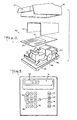
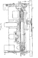
- the mailing machine 30 includes a cover 32 having a pivotal lid 34, a slot 36 therein with a closed end 38 at the right hand side thereof as seen in Fig. 1. A portion of the slot 36 forms a deck 37.
- a display panel 40 and control panel 42 having openings 43 therein.
- the cover 32 and an electromagnetic insulating shield 44 are attached to a base 46, the cover and base together forming a housing.
- a pan 48 that contains a logic board 49.
- a power supply board 50, a display board 52 and a keyboard 54 are supported within the cover 32, the display board 52 being aligned with an opening in the display panel 40 and the keyboard 54 being aligned with the control panel 42.
- the keyboard 54 serves as an information inputting and information retrieval device and has a number of keys which extend into the openings 43 of the control panel 42 and become part of the control panel.
- Numeric setting keys 56, a clear key 58 and a decimal key 60 are located on the left hand side of the control panel 42.
- On the right hand side of the control panel 42 are a postage used key 62, a postage unused key 64, a postage sum or piece count key 66 and a select postage key 68.
- selection keys for remote meter resetting operation including an authorization key 70, an enter amount key 72, and an enter combination key 73.
- a date key 74 and a plurality of thumb wheels 75 which are connected to the date printing mechanism that will be described hereinafter.
- the keys on the control panel 42 are membrane switches. Shown on the display panel 40 is a check date indicator 76 that is electrically connected to the date key 74.
- An on/off power switch 78 is located on the side of the cover 32 for the control of power to be supplied to the electrical components of the mailing machine 30.
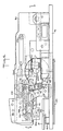
- the mailing machine 30 includes a pair of opposite side frames 80 and 81 supported by the base 46.
- a drive motor 82 is located between the side frames 80, 81 and mounted on the base 46.
- the output shaft 84 of the drive motor 82 has a gear 86 secured thereto.
- a shaft 88 is supported within ball bearings 90 (only one being shown) supported by opposed walls 92 and 93.
- a gear 94 is mounted on the shaft 88 and meshes with the gear 86 on the drive shaft 84 to be driven thereby.
- a worm screw 96 is formed on the shaft 88 and meshes with a disc gear 98 of a single revolution spring clutch 100.
- a wall 102 extends between the walls 92, 93 and receives a shaft 104 therein, the other end of the shaft being supported by an opposite wall 103.
- Print cams 106,108 are secured to opposite ends of the shaft 104 and another print cam 107 is secured to the shaft intermediate the two print cams ( Figure 7).
- a die shelf extension bracket 110, a print bracket 111 and a rectifier bracket 112 recieve a shaft 114 ( Figure 8), the print bracket being secured to the shaft 114 by set screws 115 for rotation therewith.
- a lever 116 is attached to the shaft 114 and has a cam follower 118 rotatably connected thereto by a pin 120.
- the cam follower 118 engages the cam 107 to be pivoted thereby and causes rotation of the shaft 114 which carries the rectifier bracket 112 therewith.
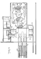
- a print head shown generally at 122 is supported within the rectifier bracket 112 and includes the print bracket 111, and the deck 37 has an opening 124 that is spaced relative to the print head ( Figure 4).
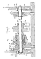
- the spring clutch shown generally at 100 includes the disc gear 98 and the shaft 104.
- a slidable member 126 is splined to the shaft 104 for rotation therewith and has an opening 128 therein.
- a confiner 130 is disposed about the slidable member 126 and a coil spring 132 is located between the slidable member and the confiner.
- One end of the spring 132 is received within the opening 128 of the slidable member 126 and the other end of the spring has a tab 134 that is received within an opening 136 of the confiner 130.
- a collar 138 is secured to the shaft 104 by a set screw 140 to limit the movement of the slidable member 126 and the confiner 130.
- a bushing 142 that is received within the wall 102 for the purpose of supporting the shaft 104.
- a bearing 144 is located within the bushing 142 and receives the shaft 104 to allow the shaft to rotate within the wall 102.
- the cam 106 is secured to the portion of the shaft 104 that extends beyond the bearing member 144.
- the cam 106 has a cam track 146 therein.
- the cam track 146 receives a cam follower 148 that is rotatably connected to an inking arm 150.
- the cam 106 has a second cam track 152 that receives a cam follower 154 that is rotatably secured to a printing arm 156.
- the cam 108 is secured to the opposite end of the shaft 104 and has a cam track 158 that receives a cam follower 160 that is rotatably attached to another printing arm 162.
- a bearing 164 is located within the support wall 103 and receives the cam 107 therein, the cam being secured to the shaft 104 for rotation therewith. Also rotatably secured to the shaft 104 is another cam 168 having a pair of cam surfaces 170 and 172 with a step 174 formed therein (also see Figs. 19 and 20). The radius of the step 174 is greater than the radius of the cam surfaces 170, 172.
- a substantially square bearing member 176 is engageable with the step 174 and a rotatable cam follower 178 is engageable with the cam surfaces 170, 172.
- the cam follower 178 is mounted by a pin 180 attached to the bearing member 176 which is formed as one end of an arm 182 that is attached at its other end to a lever 184 by a stub shaft 186 for movement therewith.
- the stub shaft 186 is rotatably received within an opening (not shown) of the base 46 and is connected to the lever 184 which is located below the base.
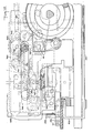
- a pair of stanchions 188 and 190 (Figs. 5 and 9) are laterally spaced opposite one another and are supported by the base 46. Received within the stanchions 188, 190 are a pair of stub shafts 192 and 194, respectively. A pair of platen arms 196 and 198 are supported by the stub shafts 192,194, respectively, so as to rotate relative to the stanchions 188, 190.
- a grooved pin 200 is supported by the printing arm 162 and a companion pin 202 is supported by the platen arm 196.
- a tension spring 204 is mounted upon a hub 206 and engages the pins 200 and 202 so that the arms 162 and 196 are resiliently connected to one another.
- the hub 206 is riveted to the printing arm 162. Corresponding pins 208 (only one shown), spring 210 and hub 212 are associated with the printing arm 156 and platen arm 198.
- a platen assembly is shown generally at 214 spaced relative to a casting 216 that is attached to the side frames 80,81.
- the platen assembly 214 includes a pair of opposed pins 218 and 219 that are received within the platen arms 196, 198, respectively.
- a platen bracket 220 is secured to the pins 218, 219 and extends therebetween at the location of the opening 124 in the deck 37, the platen bracket receiving a foam rubber platen 222.
- the platen 222 is vulcanized to the platen bracket 220 to be secured thereto and extends parallel to the print head 122, a date printer 224 and a slogan die 226 all of which are housed within the casting 216.
- the date printer 224 has plurality of wheels 225 (only partially shown in Fig. 11) that are rotatably engaged by the thumb wheels 75 (Fig. 1) to be set thereby.
- a pair of studs 228 are attached to one side of the platen bracket 220 and are received within elongated openings 230 of a stripper bracket 232.
- the stripper bracket 232 has an upper lip 233 that projects from the stripper bracket intermediate the platen 222 and the print head 122.
- an envelope 234 can be placed upon the deck 37 to be located intermediate the lip 233 of the stripper bracket 232 and the platen 222.
- a leaf spring 236 is riveted to the bottom of the platen bracket 220 and engages legs 238 that depend from the stripper bracket 232 to thereby bias the stripper bracket away from the platen 222. It will be noted that the stripper bracket 232 is slidable relative to the platen bracket 220 and is engageable with the casting 216. Depending from the platen bracket 220 is a tab 240 that receives a pin 242 to which a leveler link 244 is rotatably attached. The other end of the leveler link 244 is rotatably secured to the base 46 by a pin 246.
- the die shelf extension bracket 110 receives a trip shaft 248 that has a trip lever 250 secured thereto for rotation therweith.
- the trip lever 250 has a bar 252 attached thereto and the bar engages the inside surface of a pivot member 256.
- the pivot member 256 has a post 258 thereon and is rotatably supported by a shaft 260.
- a bearing surface 262 At one end of the pivot member 256 is a bearing surface 262 which is positioned to be engageable with an abutment surface 264 of the confiner 130.
- At the other end of the pivot member 256 is another bearing surface 266.
- the pivot member 256 also has a shoulder 268 thereon which is adapted to mate with one end 270 of another pivot member 272, the pivot member 272 having a post 274 thereon and being rotatable about a shaft 276.
- a spring 278 is secured to the posts 258, 274 so as to urge the surface 268 of the pivot member 256 and the pivot member 256 toward one anotherthrough rotation of the pivot member 256 in the clockwise direction and the pivot member 272 in a counter- clockwise direction as seen in Figs. 15-18.
- the pivot member 272 has a bearing surface 280 on the other end thereof which is engageable with a shoulder 282 of the confiner 130.
- the confiner 130 has a projecting portion 284 forming another shoulder 286 that is engageable by a depending member 288 of the pivot member 272.
- Attached to a support bracket 290 that is mounted on the base 46 is a switch 291 having an actuator 293 that is engaged by a bearing surface 279 of, the pivot member 272.
- the die shelf extension bracket 110 rotatably supports a tri-lobe shaft 292 which is received within opposed openings 294 of a carriage 296 so that it may rotate therein without interference.
- the carriage 296 is slidably retained and guided by a pair of shafts 298 and 300 and has a slot 302 therein.
- a selector gear 304 is mounted on the tri-lobe shaft 292 and disposed within an opening 305 of the carriage 296.
- a gear 306 is secured to the tri-lobe shaft 292 outside of the die shelf extension bracket 110.
- the trip shaft 248 has a locking lever 308 that is receivable within the slot 302 of the carriage 296 and a gear segment 310 is mounted on the trip shaft 248 to be rotated thereby.
- the trip shaft 248 passes through clearance openings in the rectifier bracket 112.
- the carriage 296 has tooth forms 311 at the bottom thereof as seen in Fig. 8. These tooth forms 311 extend parellel to the shaft 292.
- a first electrical setting means in the form of a stepper motor 312 which has a gear 314 mounted on the output shaft 316 thereof.
- the gear 314 is in mesh with the gear 306 that is mounted on the tri-lobed shaft 292.
- an optical encoder disk 318 mounted on the output shaft 316 of the stepper motor 312 is an optical encoder disk 318 that is received within a sensor 320 whereby the instantaneous position of the stepper motor shaft 316 can be determined.
- a second electrical setting means in the form of a stepper motor 322 is mounted on the base 46 and has a gear 324 mounted on the output shaft 326 thereof.
- An optical encoder disk 328 is also mounted on the output shaft 326 for determining the angular position of the gear 324 and an alignment mark 329 thereon. Such determination is accomplished with an optical sensor 330 that has a pair of opposed plates or walls 332 and 333 that defined a space therebetween one wall 332 having an alignment mark331 thereon.
- the optical encoder disk 328 is partially received within such opening.
- One wall 332 has a pair of light sources 334, (for example, light emitting diodes) and the other wall 333 has a pair of light responsive devices, such as photocells 336, aligned with the light sources.
- the housing of the optical sensor 330 has a pair of guide pins 338 extending therefrom that are received within measured openings of a mounting bracket 339.
- a gear 340 is mounted on a shaft 342 and meshingly engages the stepper motor gear 324.
- the carriage 296 has teeth 344 thereon that are engaged by the gear 340 whereby the carriage may be laterally moved along the shafts 298 and 300 upon rotation of the gear 340.
- the optical encoder disk 318 and the sensor 320 are of the same construction as the optical encoder disk 328 and the sensor 330, respectively.
- the shaft 292 is supported by the die shelf extension bracket 110 and has mounted thereon the gears 304 and 306.
- the gear 304 is engageable with the upper teeth 346 of four racks 348, which racks have lower teeth 350 at the other longitudinal end thereof.
- the lower teeth 350 of each rack 348 engage gears 352 that are integral with print wheels 354, there being a corresponding print wheel for each rack.
- the print wheels 354 have fonts 356 distributed about their perimeters, each font of each wheel being of a different number from 0 to 9.
- An inker rack 358 has an elongated opening 360 therein with teeth 362 projecting into the opening.
- the inking arm 150 has teeth 364 at one end thereof and is mounted upon a shaft 366 at its other end for pivoting thereabout. With this structure, as the cam 106 is rotated by the shaft 104, the cam follower 148 on the inking arm 150 will cause the inking arm to pivot about the shaft 366 thereby accurately driving the teeth 364 with a reciprocating motion.
- a compounded gear 368 has a small diameter gear portion 370 and a large diameter gear portion 372, the small diameter portion 370 being engaged by the teeth 364 of the inking arm 150.
- the large diameter gear portion 372 engages a gear 374, which gear is in engagement with the teeth 362 of the inker rack 358.
- the inker rack 358 also has a pin 376 thereon which is received within an opening 378 of the side frame 81 thereby providing support to the inker rack.
- a tie bar 380 (only one end thereof being shown) is integrally secured to the inker rack 358 and has end brackets 382 (only one shown) on opposite ends thereof.
- the end brackets 382 have slots 384 with a ridge 386 located at the open end of the slots.
- a roller housing 388 rotatably receives an ink roller 390 which has a shaft 392 extending therethrough. The ends 394 of the shaft 392 are received within lugs 396 located at opposite sides of the roller housing 388 and which are adapted to be received within the slots 384 to support the housing 388 within the tie bar 380.
- a slit 398 is located within each lug 396 to allow the shaft ends 394 to be received therein thereby rotatably supporting the ink roller 390 within the roller housing 388. It will be appreciated that any ink roller support structure may be used and the one described does not form part of the instant invention. It is included only for the purpose of illustrating the type of structure that may be used.
- a generally "L" shaped member 400 is integral with one end of the lever 184 and has an opening 402 that receives one end of an extension spring 404.
- the member 400 also has a leg 405 that extends parallel to the lever 184.
- the other end of the spring 404 is received within an opening 406 of a frame member 408.
- a post 410 is integral with a slid member 412 and received within an elongated opening 414 of the leg 405.
- the spring 404 exerts a force upon the lever 184 causing the lever to force the cam follower 178 against the cam surface 172 or the bearing member 176 against the cam surface 170 depending upon the angular posture of the cam 168.
- the slid member 412 has a T-shaped pusher 416 at its end opposite the post 410, which pusher has a wall portion 418 and a connector 420 that is received within a channel 422 of the base 46.
- a stub shaft 424 is secured to an arm 426 and is rotatably supported by the casting 216.
- a spring 428 is wrapped around the stub shaft 424 and has one end attached to the casting 216 and the other end engages the arm 426 to bias the arm in a downward direction so that a roller 430 which is rotatably attached to the arm by a pin 432 is urged downwardly onto the deck 37.
- a pivot pin 434 is mounted on the base 46 and pivotally supports a lever 436.
- a torsion spring 438 is secured at one end to the base 46 and engages the lever 436 at its other end to urge the lever in a clockwise direction as seen in Fig. 19.
- the lever 436 has a letter contacting tip 440 at one end thereof and a depending finger 442 opposed thereto that extends through an opening 444 in the base 46.
- a photosensor 446 is mounted on the logic bracket 49 and is in a position to receive the finger 442 when the lever 436 pivots in the counter-clockwise direction.
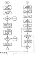
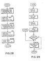
- Fig. 26 a block diagram is shown of the electrical circuit of the mailing machine and in Figs. 27, 27a, 27b, 28 and 29 a flow chart is shown that describes operation of the mailing machine 30.
- the electrical circuit includes an 8-bit microprocessor 448 (CPU), such as an Intel Model 8085 microprocessor, which controls the functions of the mailing machine 30 and is connected to various components of the electrical circuit through a system bus 450.
- the microprocessor 448 is in electrical connection with a ROM 452 through the system bus 450.
- the ROM 452 serves as an address latch that formats address signals and stores a series of programs for controlling the mailing machine 30.
- integrated circuit 456 which may be an Intel Model 8155, is also connected to the system bus 450 and includes a RAM with input lines and output lines and a timer.
- the RAM 456 has memory space allocated for ascending register and descending register data for transient storage.
- External communication data ports 464 are connected to the microprocessor 448 through optical isolators 466. These external communication ports allow connection with devices such as an electronic scale, a remote meter resetting system, servicing equipment and the like.
- the keyboard 54 Also in connection with the microprocessor 408 through the system bus 450 is the keyboard 54 and a non-volatile memory (NVM) 468.
- the stepper motors 312, 322 are also in electrical connection with the microprocessor 448 via the RAM 456 and bus 450 or reset controls 472.
- a reset and power control unit 472 is electrically connected between the RAM 456 and the microprocessor 448 and a relay 474 connects the motor 82 to the RAM 456.
- the mailing machine 30 is first prepared for operation by turning on the power switch 78.
- the check data indicator 76 an LED, on the display panel 40 will start flashing for the purpose of warning the operator to check the date for which the date printer 224 is set.
- This indicator 76 will flash a signal to indicate that the microprocessor 448 has disabled the mailing machine 30.
- the lid 34 would then be lifted by the operator to expose the date key 74 and the thumb wheels 75. The operator would then operate the thumb wheels 75 to change the date print wheels 225, if necessary, and would then depress the date switch key 74.
- the print head 122 is in the home position as indicated in Fig. 4 and the printing cams 106,108 will be positioned to place the cam followers 148, 160 in locations so as to cause the print bracket 111 to raise the print head within the cover 32 away from the deck 37 so that it cannot be contacted or wiped to obtain an unauthorized impression.
- the carriage 296 and selector gear 304 will be located in the home position and the locking lever 308 will be located outside of the carriage slot 302 as seen in Fig. 8. In such position, the selector gear 304 is out of engagement with all the racks 348 (Fig. 5) which are locked in position by engagement between the upper rack teeth 346 and the tooth forms 311.
- Postage values are selected by first entering the values through the numeric setting keys 56 of the keyboard 42. Such value selections are indicated at the display panel 40.
- the display board 52 may be set to zero by depression of the clear key 58 and then a new value may be entered.
- the select postage key 68 is depressed and the microprocessor 448 will cause the print wheels 354 to be set for the selected postage by controlling the stepper motors 312, 322.
- a signal is sent to the microprocessor 448.
- the microprocessor 448 operates in accordance with a control program stored in the ROM 452 which is accessed over address lines.
- the microprocessor 448 accesses data stored in the RAM 456 over the system bus 450.
- the data in the RAM 456 represents positions for which the stepper motors 312, 322 had been set.
- the stepper motors 312, 322 are set relatively by the microprocessor 448 based on their present dispositions and the new positions to be assumed. Upon being so set data representations of the new positions of the stepper motors 312, 322 are supplied to and stored in the RAM 456.
- the spring clutch 100 Prior to depression of the select postage key 68, the spring clutch 100 will be in the home position as shown in Fig. 15. At this time, the trip shaft 248 will be in a position such that the locking lever 308 is removed from the carriage slot 302 thereby freeing the carriage 296 for movement along the shaft 292.
- stepper motors 312, 322 selection of postage values is accomplished by the stepper motors 312, 322 through control of the microprocessor 448.
- the stepper motor 312 causes a selected print wheel 354 to be rotated while the other stepper motor 322 determines the bank to be acted upon by the stepper motor 312, the term bank including the rack 348, gear 352, print wheel 354 and other components associated with the rotation of a given print wheel.
- the microprocessor 448 will control the movement of the stepper motor 322 through the RAM 456 so that the selector gear 304 carried by the carriage 296 will address each bank in sequence.
- Movement of the carriage 296 is accomplished in incremented rotation of the gear 324 which in turn will rotate the carriage gear 340 thereby causing the carriage 296 to slide along the tri-lobe shaft 292.
- the position of the carriage 296 is determined by the optical sensor 330 that senses the angular displacement of the optical encoder 328 mounted on the output shaft 326 of the stepper motor 322.
- the stepper motor 312 will be enabled through control of the microprocessor 448 to rotate the addressed print wheel 354 and place it into the position selected by the numeric setting keys 56.
- This rotation is caused by the rotation of the selector gear 304, by the stepper motor 312 via gear 306 and shaft 292, whose teeth engage the upper teeth 346 of the particular rack 348 being acted upon to move it longitudinally to the selected position.
- the lower teeth 350 will cause rotation of the print wheel 354 through interaction with the gear 352.
- Each stepper motor 312, 322 is provided with a two channel optical encoder 318, 328, respectively, to permit the microprocessor 448 to determine the setting of the print wheels 354 and position of the carriage 296, respectively, and to detect unauthorized wheel movements.
- the two channel encoder 318, 328 a determination can be made of the direction of rotation of the stepper motor by the sequence in which the lights 334 are exposed.
- the sensor 330 has a pair of pins 338 thereon that are adapted to fit with openings of the mounting bracket 339. In this way, proper alignment of the optical sensor 330 is assured.
- the upper wall 332 of the sensor 330 has a mark 331 thereon that is used for the purpose of setting the optical encoder disk 328.
- the carriage 296 After the print wheels 354 are placed in their appropriate position as described, the carriage 296 will be placed in its home position as seen in Fig. 8.
- the microprocessor 448 would cause the stepper motor 312 to rotate the trip shaft 248 slightly and place the spring clutch 100 in the locked position as shown in Fig. 16.
- the locking lever 308 In such locked position, the locking lever 308 would enter the slot 302 to lock the carriage 296.
- the tooth forms 311 would engage the upper teeth 346 of the racks 344 thereby locking the print wheels 354 at the selected values.
- An envelope 234 to be stamped would be placed into the slot 36 and its presence sensed by the photosensor 446.
- Fig. 15 the trip shaft 248 is shown in its home position, i.e. in this position the pivot member 256 is in a position such that the shoulder 268 is contacted by the end 270 of the pivot member 272 and the bearing surface 280 is in engagement with the shoulder 282.
- the spring 132 would be held loosely about the slidable member 126. No movement can be imparted from the disc gear 98 to the slidable member 126 because of the posture of the spring 132. Consequently, the shaft 104 can have no drive imparted thereto.
- the print wheels 354 may be rotated so as to adjust the settings on the print head 122.
- the bar 252 begins to slide upon the curved surface 254 and will first assume the locked position as shown in Fig. 16.
- the components of the single revolution clutch 100 still occupy the same status as in the home position with the exception that the trip shaft 248 is in a position whereby the locking lever 308 is received with the carriage slot 302 to lock the carriage 296 and the racks 348 as previously described.
- the bar 252 will then become disengaged from the surface 254 and the pivot member 256 is free to be rotated.
- the bar 252 Upon further rotation of the trip shaft 248, the bar 252 will contact the bearing surface 266 thereby causing the pivot member 256 to rotate about the shaft 260 in a counterclockwise direction as seen in Fig. 18.
- the contact between the bar 252 and the pivot member is instantaneous, i.e., only sufficiently long to allow rotation of the pivot member.
- the pivot member 272 is rotated about the shaft 276 in a counterclockwise direction by the action of the extension spring 278 so that the bearing surface 280 is driven out of engagement with the shoulder 282 and the pivot member 256 engages the abutment surface 264 to prevent movement of the driven member in the clockwise direction.
- This will free the confiner 130 for rotation in the counterclockwise direction and the spring 132 will wrap about the gear 98 and slidable member 126 thereby providing drive connection therebetween so that the drive from the gear 98 is imparted to the slidable member 126 and confiner 130.
- the pivot members 256 and 272 follow various cam surfaces of the confiner 130.
- the completion of a printing cycle is indicated by the switch 291.
- the depending member 288 would ride upon the projecting portion 284 thereby rotating the pivot member 272 in a clockwise direction. This will drive the bearing surface 279 into engagement with the actuator 293 to actuate the switch 291.
- the switch 291 Upon actuation, the switch 291 would send a signal to the microprocessor 448 to indicate the completion of the cycle and the microprocessor will send a signal to charge the postage used in the printing by reducing the amount of postage stored in the RAM 456.
- the microprocessor 448 will also clear the mailing machine 30 so that it is ready for another operation.
- an alternative way of determining that a printing cycle has taken place for purposes of accounting would be through the optical sensor 320 associated with the encoder disk 318 secured to the output shaft 316 of the stepper motor 312.
- the gear 304 will be out of engagement with all the racks 348 and will engage the gear segment 310.
- Such position of the carriage 296 will be sensed by the sensor 330 in cooperation with the encoder disk 329 and this will be communicated to the microprocessor 446.
- the trip shaft 248 will be rotated in a first direction by the stepper motor 312 through the segment gear 310 to trip the single revolution clutch 100 so that the clutch will bring about the postage printing operation.
- the trip shaft 248 Upon completion of the printing cycle, the trip shaft 248 would be returned to the home position and the output shaft 316 would be rotated in the opposite direction. Such return movement of the trip shaft 248 would be observed by the sensor 320 which would send a signal to the microprocessor 448 to indicate the end of a print cycle. Confirmation that rotation has taken place is transmitted by the two photodetectors 325 which, in cooperation with the two lights 323, can not only determine that the disk encoder 328 is being rotated by the output shaft 326 of the bank stepper motor 312 but also in which direction. In the mode of operation herein described when the rotation of the output shaft 316 is in a first direction, the microprocessor 448 controls the printing operation and will charge the appropriate postage amount. Upon rotation of the output shaft in the opposite direction, the microprocessor 448 will clear the system for additional operations.
- the platen assembly 214 is being lifted. This is accomplished by the cam followers 154, 160 following the cam tracks 152, 158, respectively, of the print cams 106 and 108. With such movement, the print arms 156, 162 will be moved upwardly thereby moving the platen arms 196, 198 through the interaction of the tension springs 204, 210. As the printing cams 106, 108 rotate, the platen arms 196, 198 will be lifted thereby carrying the platen bracket 220 upwardly with the foam rubber platen 222 therein. As the platen bracket 220 is lifted, the stripper bracket 232 contacts the casting 216 to be driven downwardly as the leaf spring 236 is overcome.
- the torsion springs 204, 210 provides compensation for variation in thickness. If a thin envelope is to be stamped, the normal biasing forces of the springs 204, 210 are sufficient to allow printing to occur. On the other hand, if a thick envelope 234 is to be stamped, the springs 204, 210 will yield to accommodate the same. The rate of the springs 204, 210 should be approximately 0.114 to 0.228 N/m (20 to 40 lb.-in), the rate of the springs of the illustrated machine 30 being 0.154 N/m (27 lb.-in). As the print bracket 220 is lowered, the stripper bracket 232 will fall and the lip 233 will engage the envelope 234 thereby stripping the same from the print head 122, in case the envelope should stick thereto.
- the inking operation also occurs during the operation cycle as the single revolution clutch is actuated. This is accomplished by the cam follower 148 following the channel 146 within the cam 106. As the cam 106 rotates, the inking arm 150 will be pivoted about the pin 366 thereby causing the teeth 364 to engage the gear small portion 370 and rotate the compound gear 368. The large diameter portion 372 of the compound gear 368 is in engagement with the gear 374 which in turn engages the teeth 362 of the inker rack 358. With such movement of the arm 150, the inker rack 358 will be moved longitudinally by interaction of the components herein described.
- the ink roller 390 will be rolled across the lowered print head 122, which lowering was previously described, prior to the platen bracket 220 being moved upwardly.
- the ink roller 390 will be rolled across the print head 122 and will come to rest while the print head moves upwardly and then downwardly again to engage the platen as described previously.
- the platen bracket 220 is lowered after printing, the inking arm 150 will begin to move in the other, or clockwise, direction thereby causing the inker rack 358 to move in the opposite longitudinal direction and cause the ink roller 390 to approach its rest or home position.
- the cam surface 172 has an irregular configuration that rises to meet the cam surface 170 whose dimension is constant.
- the cam follower 178 will ride on such cam surface 170 but as the cam 168 continues to rotate the step 174 will engage the bearing member 176. Because the step 174 has a greater radius than the cam surface 170, the bearing member 176, whose linear dimensions are substantially equal to the diameter of the cam follower 178, will contact the step 174.
- the cam follower 178 will lose contact with the surface 170 immediately before the upstream end of the bearing member 176 meets the downstream end of the step 174.
- the T-shaped pusher 416 is returned to its home position as the cam 168 begins to rotate and the cam follower 178 moves along the cam surface 172.
- the T-shaped member 416 will be at and remain in its home position while the cam follower 178 moves along the cam surface 170 at which time as the printing operation is occurring.
- the bearing member 176 Upon completion of printing, the bearing member 176 will engage and fall from the step 174 thereby causing the spring 404 to instantaneously exert a force upon the upright member 400 and pivot the lever 184 about the stub shaft 186.
- the wall portion 418 will accelerate to eject an envelope 234 from the mailing machine 40. While the T-shaped pusher 416 is in its home position, the roller 430 will be resting upon the envelope 234 and the spring 428 will cause a biasing force to be imposed by the roller 430 onto the envelope 234. As a consequence, when the T-member 416 begins to drive the envelope 234 across the slot 36, the roller 430, will impose sufficient force upon the envelope 234 and its contents so that they will move in unison. This has the advantage in that the initial impact of the T-shaped pusher 416 is not absorbed as a result of the envelope contents remaining static and the envelope 234 moving relative thereto.
- Fig. 25 The various activities and their relationship to one another are shown graphically in Fig. 25.
- the abscissa represents the angle of the spring clutch 100 relative to its home position and the ordinate indicates the component whose function is being represented. No activity takes place during the first six degrees of rotation.
- the ink roller 390 begins to move toward the print head 122.
- the print head 122 starts to move downwardly and between 34° and 50° the ink roller 390 rolls across the print head 122 to ink the same.
- Between 50° and 70° the print head 122 will move upwardly as the ink roller 390 continues to move in the same direction so as to clear the print head and avoid interference therewith.
- the ink roller 390 At 106° the ink roller 390 will be at a rest position, the position it will assume during printing of an envelope 234. The ink roller 390 will stay in such rest position between 106° and 250°.
- the platen 222 When the spring clutch 100 has rotated to the point where it is 92° from its starting position, the platen 222 will begin to rise. Between 170° and 190° the print head 122 will start descending once more and will remain lowered between 190° and 195°. At 195° the platen 222 will engage the print head 122 to perform the printing operation. Thereafter, the print head 122 will be lifted until it has returned to its home position at 210° and the platen 222 will be lowered until it reaches its home position at 260°.
- the ink roller 370 at 250° will start to move in the opposite longitudinal direction to return to its home position and will reach that status by 350°.
- the bearing surface 176 will fall down the step 174 to actuate the ejection mechanism to discharge the stamped envelope 234 from the slot 36. Thus a full print cycle will have taken place.
- the electronic mailing machine 30 is controlled by the microprocessor 448 operated under control of a series of programs stored in the ROM 452.
- the microprocessor 448 accepts information entered via the keyboard 54 or via the external communication ports 464 from external message generators.
- Critical accounting and other information is stored in the non-volatile memory 468.
- the non- volatile memory 468 may be an MOS semiconductor type memory, a battery augmented CMOS memory, or other suitable non-volatile memory component.
- the function of the non-volatile memory 468 is to store critical postage meter data during those times when power is not applied to the mailing machine 30.
- This data may include, in addition to the serial number of the mailing machine 30, information as to the amount of the descending register (the amount of postage available for printing), the value of the ascending register (the total amount of postage printed by the meter), and the value of the piece count register (the total number of cycles the meter has performed), as well as other types of data, such as service information, which are desired to be retained in the memory even though no power is applied to the meter.
- the on/off power switch 78 When the on/off power switch 78 is turned on causing the power supply internal to the mailing machine 30 (such as +5V) to energize the microprocessor 448 and the balance of the electronic components of the mailing machine.
- the information stored in the non-volatile memory 468 is transferred via the microprocessor 448 to the RAM 456.
- the RAM 456 after power up contains an image or copy of the information stored in the non-volatile memory 468 prior to energization.
- the data in the RAM 456 is modified. Accordingly, when postage is printed, the descending register will be decremented, the ascending register incremented and the piece counter register incremented.
- the updated data in the RAM 456 is transferred via the microprocessor 448 back into the non-volatile memory 468.
- the data is transferred into a suitably prepared area of the non-volatile memory468.
- the non-volatile memory468 is updated during the power down cycle when the power switch 78 is turned off. A like transfer of information between the non-volatile memory and the RAM 456 takes place during uncontrollable power failure.
- the remote resetting function is performed by first lifting the lid 34 and entering the remote resetting authorization number upon pressing the appropriate key 70.
- this information plus the postage amount desired, is entered through a telephone whereupon a coded combination is received.
- the operator enters the postage desired, then presses the RMRS enter amount key 72.
- the operator then enters the combination received from the Status Center and presses the RMRS enter combination key 73. Thereafter, the new postage unused value will be displayed, and the mailing machine 30 is ready for normal operation.
Landscapes
- Physics & Mathematics (AREA)
- General Physics & Mathematics (AREA)
- Devices For Checking Fares Or Tickets At Control Points (AREA)
- Supplying Of Containers To The Packaging Station (AREA)
- Management, Administration, Business Operations System, And Electronic Commerce (AREA)
- Massaging Devices (AREA)
- Control And Other Processes For Unpacking Of Materials (AREA)
- Mechanical Treatment Of Semiconductor (AREA)
- Oscillators With Electromechanical Resonators (AREA)
- Slot Machines And Peripheral Devices (AREA)
- Input Circuits Of Receivers And Coupling Of Receivers And Audio Equipment (AREA)
- Processing Of Stones Or Stones Resemblance Materials (AREA)
- Medicines Containing Plant Substances (AREA)
- Photoreceptors In Electrophotography (AREA)
- Data Exchanges In Wide-Area Networks (AREA)
- Information Transfer Between Computers (AREA)
- Computer And Data Communications (AREA)
- Soil Working Implements (AREA)
- Die Bonding (AREA)
- Handling Of Sheets (AREA)
Claims (23)
Priority Applications (1)
| Application Number | Priority Date | Filing Date | Title |
|---|---|---|---|
| AT83112364T ATE59718T1 (de) | 1982-12-08 | 1983-12-08 | Elektronische post bearbeitende maschine. |
Applications Claiming Priority (2)
| Application Number | Priority Date | Filing Date | Title |
|---|---|---|---|
| US447815 | 1982-12-08 | ||
| US06/447,815 US4579054A (en) | 1982-12-08 | 1982-12-08 | Stand-alone electronic mailing machine |
Publications (4)
| Publication Number | Publication Date |
|---|---|
| EP0111322A2 EP0111322A2 (fr) | 1984-06-20 |
| EP0111322A3 EP0111322A3 (en) | 1987-05-13 |
| EP0111322B1 true EP0111322B1 (fr) | 1991-01-02 |
| EP0111322B2 EP0111322B2 (fr) | 1998-07-08 |
Family
ID=23777870
Family Applications (1)
| Application Number | Title | Priority Date | Filing Date |
|---|---|---|---|
| EP83112364A Expired - Lifetime EP0111322B2 (fr) | 1982-12-08 | 1983-12-08 | Machine de traitement du courrier électronique |
Country Status (11)
| Country | Link |
|---|---|
| US (1) | US4579054A (fr) |
| EP (1) | EP0111322B2 (fr) |
| JP (1) | JP2505145B2 (fr) |
| AT (1) | ATE59718T1 (fr) |
| AU (1) | AU555377B2 (fr) |
| BR (1) | BR8306867A (fr) |
| CA (1) | CA1214276A (fr) |
| DE (1) | DE3382077D1 (fr) |
| ES (1) | ES527833A0 (fr) |
| NO (1) | NO167486C (fr) |
| ZA (1) | ZA838546B (fr) |
Families Citing this family (42)
| Publication number | Priority date | Publication date | Assignee | Title |
|---|---|---|---|---|
| US4731749A (en) * | 1984-08-22 | 1988-03-15 | Pitney Bowes Inc. | Electronic postage meter having multiple non-volatile memories for storing different historical information reflecting postage transactions |
| EP0173249B2 (fr) * | 1984-08-22 | 1998-07-08 | Pitney Bowes Inc. | Système de mémoire non-volatile avec possibilité d'enregistrement de données de temps réels et de baisse de puissance pour une machine à affranchir électronique |
| US4627016A (en) * | 1984-08-22 | 1986-12-02 | Pitney Bowes Inc. | Memory address location system for an electronic postage meter having multiple non-volatile memories |
| EP0219118B1 (fr) * | 1985-10-15 | 1991-09-25 | Pitney Bowes Inc. | Machine à affranchir électronique à double redondance |
| GB8607367D0 (en) * | 1986-03-25 | 1986-04-30 | Roneo Alcatel Ltd | Position sensor |
| CA1326402C (fr) * | 1987-10-27 | 1994-01-25 | Gilbert N. Riley | Dispositif anti-fraude pour machine a affranchir electronique |
| CA1330409C (fr) * | 1987-12-17 | 1994-06-28 | Donald T. Dolan | Machine a courrier modulaire |
| US4923023A (en) * | 1987-12-17 | 1990-05-08 | Pitney Bowes Inc. | Modular mailing machine |
| US4893249A (en) * | 1987-12-17 | 1990-01-09 | Pitney Bowes, Inc. | Mailing machine |
| US4864924A (en) * | 1987-12-21 | 1989-09-12 | Pitney Bowes Inc. | Printwheel detent disengaging apparatus |
| US4852482A (en) * | 1987-12-21 | 1989-08-01 | Pitney Bowes Inc. | Automatic printwheel setting system |
| US5049727A (en) * | 1988-12-28 | 1991-09-17 | Pitney Bowes Inc. | Locking device for removable postage meter |
| US4945831A (en) * | 1988-12-28 | 1990-08-07 | Pitney Bowes Inc. | Ink tray drive |
| US4935078A (en) * | 1988-12-28 | 1990-06-19 | Pitney Bowes Inc. | High throughput mailing maching timing |
| US4884503A (en) * | 1989-02-08 | 1989-12-05 | Pitney Bowes Inc. | Mailing machine including improved sheet feeding means |
| USD323526S (en) | 1989-07-11 | 1992-01-28 | Seiko Epson Corporation | Printer for electronic computer |
| USD320226S (en) | 1989-12-11 | 1991-09-24 | Ncr Corporation | Document/passbook printer |
| FR2684335B1 (fr) * | 1991-11-29 | 1995-06-16 | Alcatel Satmam | Dispositif de commande pour machine d'impression a la volee, et procede correspondant. |
| US5325773A (en) * | 1992-12-28 | 1994-07-05 | Pitney Bowes Inc. | Multi-value dispensing apparatus |
| CA2111288C (fr) * | 1992-12-28 | 1997-07-01 | Flavio M. Manduley | Appareil de distribution de timbres d'une seule valeur |
| US5295433A (en) * | 1993-07-02 | 1994-03-22 | Pitney Bowes Inc. | Value selection mechanism including means for weakening a shaft thereof |
| US5452654A (en) * | 1993-07-13 | 1995-09-26 | Pitney Bowes Inc. | Postage metering system with short paid mail deterrence |
| US5655023A (en) * | 1994-05-13 | 1997-08-05 | Pitney Bowes Inc. | Advanced postage payment system employing pre-computed digital tokens and with enhanced security |
| US5586036A (en) * | 1994-07-05 | 1996-12-17 | Pitney Bowes Inc. | Postage payment system with security for sensitive mailer data and enhanced carrier data functionality |
| US5612889A (en) * | 1994-10-04 | 1997-03-18 | Pitney Bowes Inc. | Mail processing system with unique mailpiece authorization assigned in advance of mailpieces entering carrier service mail processing stream |
| FR2730668B1 (fr) * | 1995-02-20 | 1997-05-30 | Secap | Dispositif et procede de pilotage d'une machine d'impression notamment de tambour d'affranchisseur |
| US5654614A (en) * | 1995-04-14 | 1997-08-05 | Ascom Hasler Mailing Systems Ag | Single-motor setting and printing postage meter |
| US5731980A (en) * | 1996-08-23 | 1998-03-24 | Pitney Bowes Inc. | Electronic postage meter system having internal accounting system and removable external accounting system |
| US5812400A (en) * | 1996-08-23 | 1998-09-22 | Pitney Bowes Inc. | Electronic postage meter installation and location movement system |
| US6007178A (en) * | 1996-08-23 | 1999-12-28 | Pitney Bowes Inc. | Drive gear system using a single motor for a priming operation and driving a platen in a postage meter |
| US6050486A (en) * | 1996-08-23 | 2000-04-18 | Pitney Bowes Inc. | Electronic postage meter system separable printer and accounting arrangement incorporating partition of indicia and accounting information |
| US5999921A (en) * | 1997-04-30 | 1999-12-07 | Pitney Bowes Inc. | Electronic postage meter system having plural clock system providing enhanced security |
| US6058190A (en) * | 1997-05-27 | 2000-05-02 | Pitney Bowes Inc. | Method and system for automatic recognition of digital indicia images deliberately distorted to be non readable |
| US6175827B1 (en) | 1998-03-31 | 2001-01-16 | Pitney Bowes Inc. | Robus digital token generation and verification system accommodating token verification where addressee information cannot be recreated automated mail processing |
| CA99144S (en) | 2002-04-10 | 2003-04-30 | Rdm Corp | Document processing device |
| GB0321826D0 (en) * | 2003-09-18 | 2003-10-15 | Graphic Internat Ltd Ab | Improvements in and relating to rotary dies and rotary printing units |
| US7475041B2 (en) * | 2003-11-21 | 2009-01-06 | Pitney Bowes Inc. | Method and system for generating postal indicia or the like |
| US7424458B2 (en) * | 2003-11-21 | 2008-09-09 | Pitney Bowes Inc. | Method and system for generating characterizing information descriptive of printed material such as address blocks and generating postal indicia or the like incorporating such characterizing information |
| US20050131840A1 (en) * | 2003-12-15 | 2005-06-16 | Pitney Bowes Incorporated | Method and system for generating characterizing information descriptive of selected printed material such as a particular address block |
| US7668786B2 (en) * | 2003-12-15 | 2010-02-23 | Pitney Bowes Inc. | Method and system for estimating the robustness of algorithms for generating characterizing information descriptive of selected printed material such as a particular address block |
| US7437993B2 (en) * | 2005-09-23 | 2008-10-21 | Pitney Bowes Inc. | Postage meter with improved printing slot |
| KR102505952B1 (ko) * | 2018-02-19 | 2023-03-03 | 한화에어로스페이스 주식회사 | 신호 값을 저장하는 제어 시스템 |
Family Cites Families (24)
| Publication number | Priority date | Publication date | Assignee | Title |
|---|---|---|---|---|
| US3069084A (en) * | 1962-12-18 | Registering mechanism | ||
| US2639665A (en) * | 1953-05-26 | Mail marking machine fob sheets | ||
| CH89342A (de) * | 1920-05-26 | 1921-07-01 | Bodler L Alfred | Frankierapparat. |
| CH153973A (de) * | 1931-07-25 | 1932-04-15 | Safag A G | Einrichtung an Frankiermaschinen zur Sicherung des Druckwerkes gegen unkontrollierte Benützung der Druckplatten. |
| CH190847A (de) * | 1936-10-26 | 1937-05-15 | Safag A G | Frankiermaschine. |
| US3198168A (en) * | 1961-04-05 | 1965-08-03 | Addressograph Multigraph | Machines for processing printing plates and the like |
| GB1052016A (fr) * | 1962-12-28 | |||
| US3244096A (en) * | 1964-09-15 | 1966-04-05 | Pitney Bowes Inc | Imprinting machine with controlled imprinting force |
| US3310139A (en) * | 1965-07-06 | 1967-03-21 | Pitney Bowes Inc | Drive system |
| US3377882A (en) * | 1965-08-26 | 1968-04-16 | Pitney Bowes Inc | Mechanical energy storage system |
| US3363549A (en) * | 1965-09-10 | 1968-01-16 | Friden Inc | Platen control means in postage meter machines |
| US3431845A (en) * | 1966-02-04 | 1969-03-11 | Lathem Time Recorder Co | Card controlled printing and numbering means |
| US3384302A (en) * | 1966-02-16 | 1968-05-21 | Pitney Bowes Inc | Carriage restoring mechanism |
| US3693543A (en) * | 1970-10-26 | 1972-09-26 | Singer Co | Imprinting mechanism |
| US3823666A (en) * | 1970-11-23 | 1974-07-16 | Pitney Bowes Inc | Value dispensing mechanisms |
| GB1482970A (en) * | 1974-10-14 | 1977-08-17 | Amano Corp | Printer |
| US3978457A (en) * | 1974-12-23 | 1976-08-31 | Pitney-Bowes, Inc. | Microcomputerized electronic postage meter system |
| US4246643A (en) * | 1978-02-13 | 1981-01-20 | Pitney Bowes Inc. | Low cost postage applicator |
| JPS5615380A (en) * | 1979-07-19 | 1981-02-14 | Ricoh Co Ltd | Platen displacing device |
| US4259902A (en) * | 1979-10-30 | 1981-04-07 | Pitney Bowes Inc. | Electronic postage meter with power failure accounting protection system |
| GB2079223B (en) * | 1980-07-09 | 1984-03-14 | Roneo Alcatel Ltd | Postal franking meter |
| FR2486687B1 (fr) * | 1980-07-09 | 1986-08-22 | Roneo Alcatel Ltd | Compteur d'affranchissement postal |
| US4448122A (en) * | 1982-04-14 | 1984-05-15 | Esselte Pendaflex | Print wheels having means for rotating a selected print wheel and preventing the rotation of print wheels adjacent the rotated print wheel |
| US4421023A (en) * | 1982-05-20 | 1983-12-20 | Pitney Bowes Inc. | Printer control systems for electronic postage meter |
-
1982
- 1982-12-08 US US06/447,815 patent/US4579054A/en not_active Expired - Lifetime
-
1983
- 1983-11-16 ZA ZA838546A patent/ZA838546B/xx unknown
- 1983-11-25 AU AU21702/83A patent/AU555377B2/en not_active Expired
- 1983-12-06 ES ES527833A patent/ES527833A0/es active Granted
- 1983-12-06 CA CA000442643A patent/CA1214276A/fr not_active Expired
- 1983-12-07 NO NO834503A patent/NO167486C/no unknown
- 1983-12-08 JP JP23220383A patent/JP2505145B2/ja not_active Expired - Lifetime
- 1983-12-08 BR BR8306867A patent/BR8306867A/pt not_active IP Right Cessation
- 1983-12-08 DE DE8383112364T patent/DE3382077D1/de not_active Expired - Lifetime
- 1983-12-08 AT AT83112364T patent/ATE59718T1/de not_active IP Right Cessation
- 1983-12-08 EP EP83112364A patent/EP0111322B2/fr not_active Expired - Lifetime
Also Published As
| Publication number | Publication date |
|---|---|
| US4579054A (en) | 1986-04-01 |
| JPS59112378A (ja) | 1984-06-28 |
| DE3382077D1 (de) | 1991-02-07 |
| ATE59718T1 (de) | 1991-01-15 |
| NO167486B (no) | 1991-07-29 |
| EP0111322A3 (en) | 1987-05-13 |
| JP2505145B2 (ja) | 1996-06-05 |
| ZA838546B (en) | 1984-07-25 |
| EP0111322B2 (fr) | 1998-07-08 |
| ES8505122A1 (es) | 1985-05-01 |
| BR8306867A (pt) | 1984-07-24 |
| NO167486C (no) | 1991-11-06 |
| CA1214276A (fr) | 1986-11-18 |
| NO834503L (no) | 1984-06-12 |
| AU2170283A (en) | 1984-06-14 |
| AU555377B2 (en) | 1986-09-18 |
| ES527833A0 (es) | 1985-05-01 |
| EP0111322A2 (fr) | 1984-06-20 |
Similar Documents
| Publication | Publication Date | Title |
|---|---|---|
| EP0111322B1 (fr) | Machine de traitement du courrier électronique | |
| US4519048A (en) | Postage meter system for communicating platen movement to a microprocessor to signal completion of printing | |
| EP0111314B1 (fr) | Machine à traiter le courrier et mécanisme d'éjection d'enveloppe pour une telle machine | |
| CA1221579A (fr) | Machine d'affranchissement a tete d'impression retractile sur tambour | |
| AU603530B2 (en) | A removable postage meter having an indicia cover | |
| US4489651A (en) | Mailing machine having an envelope stripping device | |
| US4516014A (en) | Date checking device for electronic postage meter | |
| US4523523A (en) | Mailing machine with envelope insertion sensing apparatus | |
| EP0121153B1 (fr) | Imprimante postale ayant une tête mobile d'impression et une vitesse variable de la rotation du tambour | |
| US4492159A (en) | Postage printing apparatus having a print head with a replaceable ribbon cartridge | |
| CA1216066A (fr) | Machine d'affranchissement a tete de frappe mobile et arbre porteur creux fixe | |
| US5020428A (en) | Printed stamp machine | |
| US5749291A (en) | System for setting date wheels in a postage meter | |
| US4656341A (en) | Postage meter printhead assembly | |
| EP0118906B1 (fr) | Imprimante postale ayant une tête mobile d'impression et un tambour d'impression pivotant et une cartouche de ruban | |
| EP0737942A2 (fr) | Système de positionnement de roues de date d'une machine à affranchir | |
| JPS6145383A (ja) | 可動印刷ヘツドと可変速回転ドラムとを有する郵便料金印刷装置 |
Legal Events
| Date | Code | Title | Description |
|---|---|---|---|
| PUAI | Public reference made under article 153(3) epc to a published international application that has entered the european phase |
Free format text: ORIGINAL CODE: 0009012 |
|
| AK | Designated contracting states |
Designated state(s): AT BE CH DE FR GB IT LI LU NL SE |
|
| RAP1 | Party data changed (applicant data changed or rights of an application transferred) |
Owner name: PITNEY BOWES INC. |
|
| PUAL | Search report despatched |
Free format text: ORIGINAL CODE: 0009013 |
|
| AK | Designated contracting states |
Kind code of ref document: A3 Designated state(s): AT BE CH DE FR GB IT LI LU NL SE |
|
| 17P | Request for examination filed |
Effective date: 19871029 |
|
| 17Q | First examination report despatched |
Effective date: 19880905 |
|
| GRAA | (expected) grant |
Free format text: ORIGINAL CODE: 0009210 |
|
| AK | Designated contracting states |
Kind code of ref document: B1 Designated state(s): AT BE CH DE FR GB IT LI LU NL SE |
|
| REF | Corresponds to: |
Ref document number: 59718 Country of ref document: AT Date of ref document: 19910115 Kind code of ref document: T |
|
| ITF | It: translation for a ep patent filed | ||
| REF | Corresponds to: |
Ref document number: 3382077 Country of ref document: DE Date of ref document: 19910207 |
|
| ET | Fr: translation filed | ||
| PLBI | Opposition filed |
Free format text: ORIGINAL CODE: 0009260 |
|
| 26 | Opposition filed |
Opponent name: FRANCOTYP- POSTALIA GMBH Effective date: 19911002 |
|
| NLR1 | Nl: opposition has been filed with the epo |
Opponent name: FRANCOTYP- POSTALIA GMBH |
|
| EPTA | Lu: last paid annual fee | ||
| PGFP | Annual fee paid to national office [announced via postgrant information from national office to epo] |
Ref country code: LU Payment date: 19941101 Year of fee payment: 12 |
|
| PGFP | Annual fee paid to national office [announced via postgrant information from national office to epo] |
Ref country code: AT Payment date: 19941118 Year of fee payment: 12 |
|
| PGFP | Annual fee paid to national office [announced via postgrant information from national office to epo] |
Ref country code: SE Payment date: 19941121 Year of fee payment: 12 |
|
| PGFP | Annual fee paid to national office [announced via postgrant information from national office to epo] |
Ref country code: BE Payment date: 19941124 Year of fee payment: 12 |
|
| PGFP | Annual fee paid to national office [announced via postgrant information from national office to epo] |
Ref country code: NL Payment date: 19941231 Year of fee payment: 12 |
|
| EAL | Se: european patent in force in sweden |
Ref document number: 83112364.1 |
|
| PLAB | Opposition data, opponent's data or that of the opponent's representative modified |
Free format text: ORIGINAL CODE: 0009299OPPO |
|
| R26 | Opposition filed (corrected) |
Opponent name: FRANCOTYP-POSTALIA GMBH Effective date: 19911002 |
|
| PG25 | Lapsed in a contracting state [announced via postgrant information from national office to epo] |
Ref country code: LU Free format text: LAPSE BECAUSE OF NON-PAYMENT OF DUE FEES Effective date: 19951208 Ref country code: AT Effective date: 19951208 |
|
| PG25 | Lapsed in a contracting state [announced via postgrant information from national office to epo] |
Ref country code: SE Effective date: 19951209 |
|
| PG25 | Lapsed in a contracting state [announced via postgrant information from national office to epo] |
Ref country code: BE Effective date: 19951231 |
|
| PLAB | Opposition data, opponent's data or that of the opponent's representative modified |
Free format text: ORIGINAL CODE: 0009299OPPO |
|
| BERE | Be: lapsed |
Owner name: PITNEY BOWES INC. Effective date: 19951231 |
|
| PG25 | Lapsed in a contracting state [announced via postgrant information from national office to epo] |
Ref country code: NL Effective date: 19960701 |
|
| R26 | Opposition filed (corrected) |
Opponent name: FRANCOTYP-POSTALIA AKTIENGESELLSCHAFT & CO. Effective date: 19911002 |
|
| NLV4 | Nl: lapsed or anulled due to non-payment of the annual fee |
Effective date: 19960701 |
|
| APAC | Appeal dossier modified |
Free format text: ORIGINAL CODE: EPIDOS NOAPO |
|
| APAC | Appeal dossier modified |
Free format text: ORIGINAL CODE: EPIDOS NOAPO |
|
| PLAW | Interlocutory decision in opposition |
Free format text: ORIGINAL CODE: EPIDOS IDOP |
|
| PLAW | Interlocutory decision in opposition |
Free format text: ORIGINAL CODE: EPIDOS IDOP |
|
| PUAH | Patent maintained in amended form |
Free format text: ORIGINAL CODE: 0009272 |
|
| STAA | Information on the status of an ep patent application or granted ep patent |
Free format text: STATUS: PATENT MAINTAINED AS AMENDED |
|
| 27A | Patent maintained in amended form |
Effective date: 19980708 |
|
| AK | Designated contracting states |
Kind code of ref document: B2 Designated state(s): AT BE CH DE FR GB IT LI LU NL SE |
|
| ITF | It: translation for a ep patent filed | ||
| REG | Reference to a national code |
Ref country code: CH Ref legal event code: AEN Free format text: MAINTIEN DU BREVET DONT L'ETENDUE A ETE MODIFIEE |
|
| ET3 | Fr: translation filed ** decision concerning opposition | ||
| REG | Reference to a national code |
Ref country code: GB Ref legal event code: IF02 |
|
| PGFP | Annual fee paid to national office [announced via postgrant information from national office to epo] |
Ref country code: FR Payment date: 20021119 Year of fee payment: 20 |
|
| PGFP | Annual fee paid to national office [announced via postgrant information from national office to epo] |
Ref country code: CH Payment date: 20021122 Year of fee payment: 20 |
|
| PGFP | Annual fee paid to national office [announced via postgrant information from national office to epo] |
Ref country code: GB Payment date: 20021204 Year of fee payment: 20 |
|
| PGFP | Annual fee paid to national office [announced via postgrant information from national office to epo] |
Ref country code: DE Payment date: 20021230 Year of fee payment: 20 |
|
| PG25 | Lapsed in a contracting state [announced via postgrant information from national office to epo] |
Ref country code: LI Free format text: LAPSE BECAUSE OF EXPIRATION OF PROTECTION Effective date: 20031207 Ref country code: GB Free format text: LAPSE BECAUSE OF EXPIRATION OF PROTECTION Effective date: 20031207 Ref country code: CH Free format text: LAPSE BECAUSE OF EXPIRATION OF PROTECTION Effective date: 20031207 |
|
| REG | Reference to a national code |
Ref country code: GB Ref legal event code: PE20 |
|
| REG | Reference to a national code |
Ref country code: CH Ref legal event code: PL |
|
| APAH | Appeal reference modified |
Free format text: ORIGINAL CODE: EPIDOSCREFNO |