EP0111662A1 - Interrupteur électrique - Google Patents
Interrupteur électrique Download PDFInfo
- Publication number
- EP0111662A1 EP0111662A1 EP83110150A EP83110150A EP0111662A1 EP 0111662 A1 EP0111662 A1 EP 0111662A1 EP 83110150 A EP83110150 A EP 83110150A EP 83110150 A EP83110150 A EP 83110150A EP 0111662 A1 EP0111662 A1 EP 0111662A1
- Authority
- EP
- European Patent Office
- Prior art keywords
- contact
- lever
- point
- contact point
- extension
- Prior art date
- Legal status (The legal status is an assumption and is not a legal conclusion. Google has not performed a legal analysis and makes no representation as to the accuracy of the status listed.)
- Granted
Links
Images


Classifications
-
- H—ELECTRICITY
- H01—ELECTRIC ELEMENTS
- H01H—ELECTRIC SWITCHES; RELAYS; SELECTORS; EMERGENCY PROTECTIVE DEVICES
- H01H71/00—Details of the protective switches or relays covered by groups H01H73/00 - H01H83/00
- H01H71/002—Details of the protective switches or relays covered by groups H01H73/00 - H01H83/00 with provision for switching the neutral conductor
-
- H—ELECTRICITY
- H01—ELECTRIC ELEMENTS
- H01H—ELECTRIC SWITCHES; RELAYS; SELECTORS; EMERGENCY PROTECTIVE DEVICES
- H01H71/00—Details of the protective switches or relays covered by groups H01H73/00 - H01H83/00
- H01H71/002—Details of the protective switches or relays covered by groups H01H73/00 - H01H83/00 with provision for switching the neutral conductor
- H01H2071/004—Details of the protective switches or relays covered by groups H01H73/00 - H01H83/00 with provision for switching the neutral conductor with a tripping or current sensing device in the neutral wire, e.g. for third harmonics in a three fase system
-
- H—ELECTRICITY
- H01—ELECTRIC ELEMENTS
- H01H—ELECTRIC SWITCHES; RELAYS; SELECTORS; EMERGENCY PROTECTIVE DEVICES
- H01H71/00—Details of the protective switches or relays covered by groups H01H73/00 - H01H83/00
- H01H71/10—Operating or release mechanisms
- H01H71/1009—Interconnected mechanisms
- H01H71/1027—Interconnected mechanisms comprising a bidirectional connecting member actuated by the opening movement of one pole to trip a neighbour pole
-
- H—ELECTRICITY
- H01—ELECTRIC ELEMENTS
- H01H—ELECTRIC SWITCHES; RELAYS; SELECTORS; EMERGENCY PROTECTIVE DEVICES
- H01H71/00—Details of the protective switches or relays covered by groups H01H73/00 - H01H83/00
- H01H71/10—Operating or release mechanisms
- H01H71/12—Automatic release mechanisms with or without manual release
- H01H71/128—Manual release or trip mechanisms, e.g. for test purposes
Definitions
- the invention relates to an electrical switch, with two contact points, of which at least one is assigned an arc extinguishing device, an electromagnetic and / or a thermal release, the two contact points being accommodated one above the other in a housing and separated from one another by means of an intermediate wall.
- a switch that has two contact points in one housing. has become known from DE-AS 10 33 314.
- the housing has a base, a housing attachment and a cover; the main contact point, which is designed as a double contact point, is accommodated in the housing attachment, where the magnetic release is also located.
- An auxiliary contact which is controlled by the contact carrier of the main contact, is accommodated in the base of the housing part which receives the main contact point.
- the auxiliary contact or auxiliary contact point is also a double contact point.
- the housing is not designed in a shell construction, and arc-quenching plate assemblies, which are present in the circuit breakers currently manufactured for current limitation, are not provided. Rather, the arc is extinguished by extending it to a sufficient extent, which requires a corresponding size of the housing.
- An electrical circuit breaker in the housing of which two switch contacts are likewise accommodated, is known from DE-AS 10 98 587.
- the two switch contacts are located in parallel next to each other in a housing divided by partitions and are connected to one another by means of a connecting axis.
- the main focus of this arrangement is to draw the arc as long as possible, which is achieved by dividing the arc chambers into two subchambers by means of an intermediate wall, the arc being created in one chamber and being blown into the other chamber, which is connected to the environment via an outlet.
- DE-AS 10 98 587 shows several different housing shapes; all housing shapes do not show a shell construction.
- a circuit breaker in shell design in which two contact points are accommodated, one of which switches off or disconnects a phase conductor and the other the neutral or neutral conductor, has become known from FR-PS 24 96 335.
- the isolating contact point for the phase conductor is formed by a fixed contact piece and a movable contact piece attached to a contact lever, whereas the neutral conductor switch is formed by a double contact point which is actuated by means of the switching knob for actuating the switching contacts Switching on again is switched on or off using a connecting lever.
- the chambers in which the contact pieces are located are separated from one another by an intermediate wall; the phase conductor contact point is located above and the neutral conductor contact points below the partition in the housing.
- the arrangement according to the FR-PS is such that the contact point accommodated in the lower housing part or housing area is not suitable for switching off a phase conductor or for switching with the occurrence of an arc.
- the object of the invention is to provide a circuit breaker of the type mentioned with two contact points, which can be converted by simple measures so that either one contact point or both contact points can each be assigned an arc quenching plate package.
- the movable contact pieces of both contact points are coupled by means of a connecting rod which passes through the intermediate wall, that the magnet armature acts on the one contact piece to open it via a rotary lever which can be released when the switch is turned off, such that when the magnet armature is rotated the rotary lever is also rotated and acts on the contact lever carrying the movable contact piece approximately in the direction of the opening movement, and that when the one contact point is opened by means of the connecting rod, the other contact point is also opened.
- a nose is formed on the rotary lever or on the ratchet lever, which lies in the range of movement of the folding anchor, whereby a pawl is also formed on the rotary lever, which is used to latch the contact lever of the first contact point.
- a further advantageous embodiment can have the effect that the second contact point is assigned a second hinged anchor system, the hinged anchor of which acts on the connecting rod during a triggering process in the direction of opening the two contact points.
- an elongated hole is formed on the movable contact lever of the first contact point, in which an end of the rod connected to the switching knob is guided, a spring being provided which supports the rod presses against the end of the elongated hole facing the shift knob.
- This spring is the contact force spring for the first contact point and it also serves to hold the gear arrangement of the switch lock for the contact lever of the first contact point in two stable positions which can be converted into one another via a dead center position.
- the switch of the type mentioned is characterized in that the connecting rod protrudes beyond its point of action (point of action) on the contact lever of the first contact point and protrudes from the switch housing in the area of the switch knob, so that the second contact point is actuated by the extension the connecting lever can be switched off.
- a projection is formed on the extension, which cooperates with a projection on the rotary lever or ratchet lever, in such a way that R the rotary lever is rotated in the direction of opening the first contact point.
- a further embodiment of the invention can be characterized in that a projection is formed on the extension, which acts on the hinged anchor to twist it in the sense of unlatching the latching point.
- a further embodiment of the invention is that the extension is provided with a U-shaped extension which, in the switched-on position, engages around an extension located on the housing, the extension being in the switched-on position by means of a compression spring, that is to say in the position in which the extension extends encircling the housing extension fixed.
- the second embodiment which can be achieved from the first embodiment by only a minor modification, it is possible to switch a phase conductor with the first contact point and the neutral conductor with the second contact point.
- the assignment of the individual components to one another is selected in the second case so that the first contact point carries the phase conductor current and the second contact point in the neutral conductor is switched.
- the circuit is then such that when the two contact points are opened, the zero conductor contact and then the phase conductor contact are basically opened and, in the opposite case, the switching on, the zero conductor switch contact and then the phase conductor contact is closed. This is then achieved by a suitable arrangement of stops and points of engagement of the connecting or switching rod.
- FIG. 1 shows a schematic representation of a first embodiment of the invention.
- the switch has a housing 10 which is designed in a shell construction and has two housing shells (not shown further).
- the housing has a recess 12 in its lower area, which enables the switching device to be snapped onto a U-shaped support rail in an installation distribution.
- the housing 10 is divided into two spaces 16 and 18 by an intermediate wall 14 formed in the housing shell, the upper space 16 being one Phase conductor contact point (first contact point) 20 and the lower space 18 has a neutral contact point (second contact point) 22.
- the two contact points each consist of a movable contact piece 24 and 26 and a fixed contact piece 28 and 30.
- a first hinged armature system 32 with a yoke 33, a coil 34 and a magnetic core 35 is provided in the upper space 16.
- the magnetic core cooperates with a hinged armature 36, one end of which is supported at 37 on the yoke 33 and the other end of which is bent at a right angle and has a leg 38, the free end of which is provided with a hook 39 with which it is behind the contact lever 40 , which carries the movable contact piece 24, engages and actuates this in the event of a switch-off in the event of a short-circuit current.
- a stationary axle 41 is provided, on which a ratchet lever 42 is rotatably mounted.
- the pawl lever 42 has a nose 43 against which the end opposite the movable contact piece 24 is pressed, so that latching is effected.
- the pressing force is brought about by a shift rod 46 articulated eccentrically on a shift knob 45 rotatably mounted in an axis 44; when the switch toggle 45 is brought into the on position, it presses the contact lever 40 against the nose 43 and against the fixed contact piece and locks it.
- This spring is significantly stronger than the spring 50 because it must exert the force of the spring 50, the contact force at the upper and lower contact points 20, 22 and the latching force. It is possible to omit the spring 50, since (see below) the spring 46 can apply the opening force alone and can be used for the opening alone.
- the hinged armature 36 On the pawl 42 there is an extension 49 which projects into the path of movement of the armature 36. If, due to a short circuit, for example, the hinged armature 36 is tightened and thereby pivots about the point 37 in the direction of arrow A, the hinged armature takes the pawl lever along with the extension 49 and pivots it about the axis 41 counterclockwise in the direction of the arrow. As a result, the latch on the nose 43 is released, so that the movable contact lever 40 is pivoted about the axis 48 under the force of the spring 50, which itself is guided in an elongated hole in a manner not shown in FIG. 1. In this way, the contact point 20 is opened. At the same time, the movable contact lever is torn open via the hinged anchor and the extension 39.
- a connecting rod 53 is articulated on a pivot axis 51, which through the intermediate wall 14 extends through and is articulated at 57 on the movable contact lever 52 to which the movable contact piece 26 is attached.
- a further magnet system 54 corresponding to the magnet system 32 is provided, which in the same way as the magnet system 32 has a magnet core 55 and a magnet armature 56.
- the magnet armature interacts with the connecting rod 53 via a stop 58, so that when the magnet system 54 responds, the armature 56 actuates the connecting rod 53 via the stop 58 and opens the movable contact lever 40 together with the movable contact lever 52.
- the two contact points 20 and 22 are each assigned an arc quenching plate packet 61 and 62, so that the arc is optimally extinguished in both rooms.
- the current flows in the upper region from an input terminal 63 via a connecting line 64 to the bimetal 60; from there via the magnetic yoke 37 into the winding 34 and via a further connecting wire 64 to the movable contact piece 40; in the switched-on state, the current flows from there via the contact point 20 to the output terminal 65.
- the fixed contact piece 28 is U-shaped and has two legs 66 and 67, the leg 66 being connected to the output terminal 65, whereas the leg 67 is an arc running rail forms.
- the potential of the terminal 63 is connected to the guide plate 69 via a connecting line 68.
- the arc-quenching plate package is arranged between the guide rail 69 and the leg 67 of the fixed contact piece.
- the fixed contact piece 22 is formed in a similar manner in the lower region, the arc-quenching plate packet 62 being arranged between an arc guide rail 70 and the fixed contact piece 22.
- Input terminals 71 and 72 are also provided in the lower area; the current flows from the input terminal via a connecting line 73 to the winding of the magnet system 54 and via a further connecting line 74 to the movable contact lever 52 and from there to the contact point 22.
- the current flows via a connecting line 75 to the arc guide rail 70 of the arc quenching plate package 62
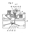
- the switch according to FIG. 2 shows an embodiment in which the neutral conductor, whose switch contact is located in the lower housing area 18, can be switched off manually.
- a magnet system 54 is missing.
- the connecting rod 80 which corresponds to the connecting rod 53 in FIG. 1, has an extension 81 which extends beyond the magnet armature 36, the end 82 of which protrudes outwards and forms a U-shape 83 there, which forms a housing extension 84 in the one shown in FIG Takes up position.
- the connecting rod 80 is then acted upon in the region of its extension 81 by a spring 85 in the direction of arrow C.
- the movable contact lever 52 is acted upon by a spring 76 which practically generates the contact pressure by rotating the movable contact lever 52 clockwise around the articulation point 57.
- the spring 50 is absolutely necessary.
- the manual switch-off of the lower contact point which is switched on in the NT, causes the switch-off of the contact point 20 via the coupling via the projection 80A, as just mentioned.
- Switching on the lower contact lever via the button 82 only causes the NT to be switched on at the contact point 22.
- the contact point 9 0 must then be switched on separately; it can also take place only after the lower contact point 22 has been switched on.
- the yoke 33 is essentially of an approximately Z-shaped shape, with the area 100 of the yoke being parallel runs to the central axis of the magnetic core 35, an leg 101, angled in an L-shape, connects, in which an adjusting screw 102 is screwed.
- an adjusting screw 102 is screwed.
- the perpendicular region 100 extends into one holding bracket 103, the other. free leg for holding the bimetallic 60 is used.
- the tip of the adjusting screw 102 presses on the inner surface of this leg with the thermobimetal 60, as a result of which the tripping can be set in the event of an overcurrent.
- this is similar for the arrangement according to FIG. 1; however, the bracket is shown differently there.
- a folding anchor 104 is mounted, which cooperates with a ratchet lever 105.
- This pawl lever 105 corresponds to the pawl lever 42, although the hinged armature 104 does not act directly on the movable contact lever 40 according to the embodiment in FIG. 3. Rather, the hinged anchor 104 acts directly on a nose 106 on the ratchet lever 105, which at 41 in the same way as that Pawl lever 42 is rotatably mounted.
- An extension 107 is also formed on the pawl lever 105, which projects into the path of movement of the movable contact lever 40.
- a rotation of the armature 104 also causes the movable contact lever 40 to rotate in the same direction via the nose 106 and the extension 107.
- a latching point 108 is provided diametrically opposite the nose 106. to which the contact lever 40 is pressed by means of the articulated gear, which is formed from the shift lever 45, the rod 46 and the support 48.
- a leaf spring 109 is guided on the movable contact lever, against which the axis 48 presses from above, so that the holder or the connection between the rod 46 and the contact lever 40 is a resilient connection.
- the spring 109 is significantly stronger than the spring 50, since it must exert both the force of the spring 50, the contact force above and below and the latching force. It is therefore possible to drop the spring 50; and the spring 109 together with the spring 76 causes both contact points to open.
- a bracket 110 is formed on the contact lever, which thereby forms a kind of elongated hole 111 with the contact lever 40 and that the axis 48 is supported by the spring 109 against the upper end, that is to say the end of the elongated hole 111, which is opposite to the contact lever.
- the thermal bimetal 60 acts in the same way as the thermal bimetal 60 of FIG. 1 on the latch lever 105 and rotates it counterclockwise about the axis 41 in the event of an overcurrent.
- a stop 120 is provided on the housing 10 in the lower region, ie below the intermediate wall 14, so that the movement of the movable contact lever 52 is limited at least at the end opposite the contact piece.
- FIG. 4 shows a switching device similar to FIG. 3 or FIG. 2; the main difference compared to FIG. 3 is that the hammer mechanism 54 is omitted.
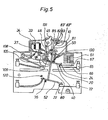
- the configuration according to FIG. 5 is constructed or varied compared to FIG. 2.
- the rod 80 is provided with an extension 81 which opens into a region 82 which forms a U-shaped recess which is delimited by a leg 83 'or 83 ".
- the coupling between the connecting rod and the contact lever 40 takes place via a projection 130 on the extension 81 and a nose 131 on This lug adjoins the projection 106 (see FIG. 3).
- the spring 76 moves the contact lever 52 and thus the connecting rod 80/81 upwards, the projection 130 via the lug 131 Latch 108 opens, thereby also opening the contact point 20, specifically by the interaction of the leaf spring 109 with the arrangement of the gear 45/46/80/40 the contact point 22 is closed independently of the contact point 20 first and only then can the Contact point 20 are closed via the shift lever 45.
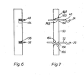
- the connecting rod 53 is shown in two views. It can be seen that the connecting rod made of plastic has two slots or two recesses 154 and 156 which are arranged at a distance from one another, such that the recess 154 lies above the intermediate wall and the recess 156 lies below the intermediate wall.
- the movable shift levers 40 and 52 are inserted into the cutouts 154 and 156.
- the recess 154 is adapted to the movement of the contact lever 40 and has two tips 160 and 162, which are not directly opposite one another, but have a distance between them in the recess 154.
- the upper tip then lies directly in the area of the left side wall and the lower tip 162 immediately in the area of the right side wall; an inclined surface 161 adjoins the upper tip 160; an inclined surface 163 adjoins the lower tip; both inclined surfaces are parallel to each other and the upper one opens to the right and the lower one to the left side wall.
- the lower recess has semicircular opposing limits 164 and 156; the lower contact lever 52 then has a bend 158 which is adapted to the limit 164 and which allows the contact lever 52 to be pivoted optimally.
- the connecting rod is made of plastic.
- the latch lever 42 or 105 is made of plastic.
- the extension 107 is at a distance from the contact lever (40). In the event of a release, the latching point is therefore only released, and after overcoming the lead due to the distance, the extension 107 acts on the contact lever.
- the hinged armature is constantly under the action of a tension spring 150, which acts continuously on the hinged armature in the switch-off direction and thereby also determines the magnetic response value.
- a spiral spring 152 is provided which continuously acts on the ratchet lever in a clockwise direction, i.e. the nose 108 constantly presses against the contact lever 40 and thus ensures the latching.
Landscapes
- Breakers (AREA)
- Emergency Protection Circuit Devices (AREA)
Priority Applications (1)
| Application Number | Priority Date | Filing Date | Title |
|---|---|---|---|
| AT83110150T ATE20405T1 (de) | 1982-11-13 | 1983-10-12 | Elektrischer schalter. |
Applications Claiming Priority (2)
| Application Number | Priority Date | Filing Date | Title |
|---|---|---|---|
| DE19823242062 DE3242062A1 (de) | 1982-11-13 | 1982-11-13 | Elektrischer schalter |
| DE3242062 | 1982-11-13 |
Publications (2)
| Publication Number | Publication Date |
|---|---|
| EP0111662A1 true EP0111662A1 (fr) | 1984-06-27 |
| EP0111662B1 EP0111662B1 (fr) | 1986-06-11 |
Family
ID=6178076
Family Applications (1)
| Application Number | Title | Priority Date | Filing Date |
|---|---|---|---|
| EP83110150A Expired EP0111662B1 (fr) | 1982-11-13 | 1983-10-12 | Interrupteur électrique |
Country Status (4)
| Country | Link |
|---|---|
| EP (1) | EP0111662B1 (fr) |
| AT (1) | ATE20405T1 (fr) |
| DE (1) | DE3242062A1 (fr) |
| ES (1) | ES8406135A1 (fr) |
Cited By (14)
| Publication number | Priority date | Publication date | Assignee | Title |
|---|---|---|---|---|
| GB2157499A (en) * | 1984-04-12 | 1985-10-23 | Bbc Brown Boveri & Cie | Electrical switch. |
| EP0155588A3 (en) * | 1984-03-20 | 1987-04-22 | Brown, Boveri & Cie Aktiengesellschaft | Electrical switch with a switching contact for a phase conductor and a switching contact for a neutral conductor |
| EP0350825A3 (fr) * | 1988-07-15 | 1991-04-17 | Asea Brown Boveri Aktiengesellschaft | Appareil de commutation électrique |
| EP0591905A1 (fr) * | 1992-10-08 | 1994-04-13 | ABBPATENT GmbH | Commutateur électrique |
| GB2295275A (en) * | 1994-11-15 | 1996-05-22 | Matsushita Electric Works Ltd | Circuit breaker |
| WO1996024150A1 (fr) * | 1995-02-03 | 1996-08-08 | Aeg Niederspannungstechnik Gmbh&Co.Kg. | Disjoncteur de protection de ligne |
| WO1998002896A1 (fr) * | 1996-07-15 | 1998-01-22 | Gewiss S.P.A. | Disjoncteur automatique modulaire avec optimisation des espaces utilises |
| FR2796488A1 (fr) * | 1999-07-14 | 2001-01-19 | Hager Electro Gmbh | Dispositif pour activer et desactiver des appareils de commutation agences sous forme de bloc |
| EP1225611A3 (fr) * | 2001-01-22 | 2004-06-09 | AEG Niederspannungstechnik GmbH & Co. KG | Disjoncteur |
| FR2866152A1 (fr) * | 2004-02-10 | 2005-08-12 | Schneider Electric Ind Sas | Disjoncteur multipolaire a blocs de coupure unipolaire |
| CN1319098C (zh) * | 1999-07-13 | 2007-05-30 | 松下电工株式会社 | 电路断路器 |
| DE102006036191A1 (de) * | 2006-08-01 | 2008-02-07 | Siemens Ag | Schaltvorrichtung |
| CN114078671A (zh) * | 2021-12-21 | 2022-02-22 | 湖北腾明智能电气有限公司 | 一种隔离式单极双断点断路器 |
| CN119008341A (zh) * | 2024-08-22 | 2024-11-22 | 桂林电子科技大学 | 一种组合断路器 |
Families Citing this family (4)
| Publication number | Priority date | Publication date | Assignee | Title |
|---|---|---|---|---|
| DE4040301A1 (de) * | 1990-12-17 | 1992-07-02 | Geyer Gmbh & Co Christian | Schaltmechanismus |
| DE19725000A1 (de) * | 1997-06-13 | 1998-12-17 | Abb Patent Gmbh | Installationsschaltgerät |
| EP1473750A1 (fr) | 2003-04-30 | 2004-11-03 | Siemens Aktiengesellschaft | Appareil interrupteur électromagnétique |
| DE102004018275B4 (de) * | 2004-04-15 | 2007-10-18 | Siemens Ag | Schaltgerät |
Citations (4)
| Publication number | Priority date | Publication date | Assignee | Title |
|---|---|---|---|---|
| DE959290C (de) * | 1954-06-01 | 1957-03-07 | Licentia Gmbh | Schaltgeraet, insbesondere Installations-Selbstschalter, mit thermischer und magnetischer Ausloesung |
| DE1033314B (de) * | 1956-12-27 | 1958-07-03 | Licentia Gmbh | Selbstschalter, insbesondere Installationsselbstschalter mit Haupt- und Hilfskontakt |
| DE1098587B (de) * | 1959-08-10 | 1961-02-02 | Licentia Gmbh | Schaltgeraet, insbesondere Installationsselbstschalter |
| EP0054499A1 (fr) * | 1980-12-16 | 1982-06-23 | Legrand | Disjoncteur à sectionnement de neutre |
Family Cites Families (9)
| Publication number | Priority date | Publication date | Assignee | Title |
|---|---|---|---|---|
| DE1003327B (de) * | 1955-02-07 | 1957-02-28 | Licentia Gmbh | Installationsselbstschalter in Schmalbauform mit magnetischer und thermischer Ausloesung und einem oder mehreren abschaltbaren Hilfskontakten fuer allgemeine Leitungsschutz- oder Spezialzwecke |
| DE1051951B (de) * | 1958-02-27 | 1959-03-05 | Ellenberger & Poensgen | Druckknopfbetaetigter UEberstromschalter |
| US3284731A (en) * | 1963-10-10 | 1966-11-08 | Heinemann Electric Co | Auxiliary switch responsive to the movement of the circuit breaker linkage |
| US3329913A (en) * | 1966-01-28 | 1967-07-04 | Heinemann Electric Co | Circuit breaker mechanism |
| DE1776082A1 (de) * | 1968-09-18 | 1971-06-09 | Babcock & Wilcox Ag | Einrichtung zur Verfeuerung fluessiger Abfallprodukte |
| GB1326186A (en) * | 1970-10-01 | 1973-08-08 | Heinemann Electric Co | Circuit breaker with on off and trip indication |
| DE2234423A1 (de) * | 1972-07-13 | 1974-01-24 | Bbc Brown Boveri & Cie | Installationsselbstschalter in schalenbauweise |
| DE3034790A1 (de) * | 1980-09-15 | 1982-03-25 | Siemens AG, 1000 Berlin und 8000 München | Leitungsschutzschalter |
| FR2496335A1 (fr) * | 1980-12-16 | 1982-06-18 | Legrand Sa | Disjoncteur a sectionnement de neutre |
-
1982
- 1982-11-13 DE DE19823242062 patent/DE3242062A1/de active Granted
-
1983
- 1983-10-12 EP EP83110150A patent/EP0111662B1/fr not_active Expired
- 1983-10-12 AT AT83110150T patent/ATE20405T1/de not_active IP Right Cessation
- 1983-10-31 ES ES526951A patent/ES8406135A1/es not_active Expired
Patent Citations (4)
| Publication number | Priority date | Publication date | Assignee | Title |
|---|---|---|---|---|
| DE959290C (de) * | 1954-06-01 | 1957-03-07 | Licentia Gmbh | Schaltgeraet, insbesondere Installations-Selbstschalter, mit thermischer und magnetischer Ausloesung |
| DE1033314B (de) * | 1956-12-27 | 1958-07-03 | Licentia Gmbh | Selbstschalter, insbesondere Installationsselbstschalter mit Haupt- und Hilfskontakt |
| DE1098587B (de) * | 1959-08-10 | 1961-02-02 | Licentia Gmbh | Schaltgeraet, insbesondere Installationsselbstschalter |
| EP0054499A1 (fr) * | 1980-12-16 | 1982-06-23 | Legrand | Disjoncteur à sectionnement de neutre |
Cited By (20)
| Publication number | Priority date | Publication date | Assignee | Title |
|---|---|---|---|---|
| EP0155588A3 (en) * | 1984-03-20 | 1987-04-22 | Brown, Boveri & Cie Aktiengesellschaft | Electrical switch with a switching contact for a phase conductor and a switching contact for a neutral conductor |
| EP0158241A3 (en) * | 1984-04-12 | 1988-04-06 | Brown, Boveri & Cie Aktiengesellschaft | Electrical switch |
| GB2157499A (en) * | 1984-04-12 | 1985-10-23 | Bbc Brown Boveri & Cie | Electrical switch. |
| EP0350825A3 (fr) * | 1988-07-15 | 1991-04-17 | Asea Brown Boveri Aktiengesellschaft | Appareil de commutation électrique |
| EP0591905A1 (fr) * | 1992-10-08 | 1994-04-13 | ABBPATENT GmbH | Commutateur électrique |
| GB2295275A (en) * | 1994-11-15 | 1996-05-22 | Matsushita Electric Works Ltd | Circuit breaker |
| GB2295275B (en) * | 1994-11-15 | 1998-08-12 | Matsushita Electric Works Ltd | Circuit breaker |
| WO1996024150A1 (fr) * | 1995-02-03 | 1996-08-08 | Aeg Niederspannungstechnik Gmbh&Co.Kg. | Disjoncteur de protection de ligne |
| WO1998002896A1 (fr) * | 1996-07-15 | 1998-01-22 | Gewiss S.P.A. | Disjoncteur automatique modulaire avec optimisation des espaces utilises |
| CN1319098C (zh) * | 1999-07-13 | 2007-05-30 | 松下电工株式会社 | 电路断路器 |
| FR2796488A1 (fr) * | 1999-07-14 | 2001-01-19 | Hager Electro Gmbh | Dispositif pour activer et desactiver des appareils de commutation agences sous forme de bloc |
| EP1225611A3 (fr) * | 2001-01-22 | 2004-06-09 | AEG Niederspannungstechnik GmbH & Co. KG | Disjoncteur |
| EP1564773A1 (fr) * | 2004-02-10 | 2005-08-17 | Schneider Electric Industries SAS | Disjoncteur multipolaire à blocs de coupure unipolaire |
| FR2866152A1 (fr) * | 2004-02-10 | 2005-08-12 | Schneider Electric Ind Sas | Disjoncteur multipolaire a blocs de coupure unipolaire |
| US7323958B2 (en) | 2004-02-10 | 2008-01-29 | Schneider Electric Industries Sas | Multipole circuit breaker with single-pole breaking units |
| CN1655306B (zh) * | 2004-02-10 | 2011-06-08 | 施耐德电器工业公司 | 带单极断开单元的多极断路器 |
| DE102006036191A1 (de) * | 2006-08-01 | 2008-02-07 | Siemens Ag | Schaltvorrichtung |
| CN101136292B (zh) * | 2006-08-01 | 2012-05-23 | 西门子公司 | 开关装置 |
| CN114078671A (zh) * | 2021-12-21 | 2022-02-22 | 湖北腾明智能电气有限公司 | 一种隔离式单极双断点断路器 |
| CN119008341A (zh) * | 2024-08-22 | 2024-11-22 | 桂林电子科技大学 | 一种组合断路器 |
Also Published As
| Publication number | Publication date |
|---|---|
| ES526951A0 (es) | 1984-07-01 |
| EP0111662B1 (fr) | 1986-06-11 |
| DE3242062C2 (fr) | 1991-01-03 |
| ES8406135A1 (es) | 1984-07-01 |
| ATE20405T1 (de) | 1986-06-15 |
| DE3242062A1 (de) | 1984-05-17 |
Similar Documents
| Publication | Publication Date | Title |
|---|---|---|
| EP0111662B1 (fr) | Interrupteur électrique | |
| EP0174904B1 (fr) | Dispositif de contact pour disjoncteur basse tension avec un levier de contact à deux bras | |
| DE2809754C2 (de) | Zweipoliger Schutzschalter | |
| EP0144799A2 (fr) | Disjoncteur | |
| WO1984001663A1 (fr) | Commutateur electrique de securite d'appareil | |
| EP0391086B1 (fr) | Dispositeur de protection à courant excessif commandé par un bouton-poussoir | |
| DE3737539C2 (fr) | ||
| EP1884976B1 (fr) | Dispositif de commutation doté d'un élément d'actionnement | |
| EP0243648B1 (fr) | Disjoncteur électrique | |
| EP0849759B1 (fr) | Appareil de coupure pour une installation électrique | |
| DE3106004A1 (de) | Leistungsschalter | |
| DD221878A1 (de) | Mehrpoliger leitungsschutzschalter | |
| EP0041049B1 (fr) | Disjoncteur de protection | |
| EP0158241B1 (fr) | Interrupteur électrique | |
| DE3734396A1 (de) | Elektrisches schaltgeraet | |
| DE68928206T2 (de) | Betätigungsmechanismus für einen mehrpoligen Fehlerstromschutzschalter mit drehbarer Schaltwelle | |
| EP0591905B1 (fr) | Commutateur électrique | |
| EP0851449B1 (fr) | Appareil de commutation pour une installation électrique | |
| AT404647B (de) | Elektrischer schutzschalter | |
| EP1488438B1 (fr) | Disjoncteur avec interruption bipolaire | |
| EP0491250A2 (fr) | Appareillage d'installation | |
| DE8904064U1 (de) | Druckknopfbetätigter Überstromschutzschalter | |
| DE2047521A1 (de) | Installationsselbstschalter mit Verteileranordnung | |
| EP0173166A2 (fr) | Couplage pour pôles de disjoncteur | |
| DE2913121A1 (de) | Mehrpoliger leistungsschalter |
Legal Events
| Date | Code | Title | Description |
|---|---|---|---|
| PUAI | Public reference made under article 153(3) epc to a published international application that has entered the european phase |
Free format text: ORIGINAL CODE: 0009012 |
|
| AK | Designated contracting states |
Designated state(s): AT BE CH FR GB IT LI NL |
|
| 17P | Request for examination filed |
Effective date: 19840711 |
|
| GRAA | (expected) grant |
Free format text: ORIGINAL CODE: 0009210 |
|
| AK | Designated contracting states |
Kind code of ref document: B1 Designated state(s): AT BE CH FR GB IT LI NL |
|
| REF | Corresponds to: |
Ref document number: 20405 Country of ref document: AT Date of ref document: 19860615 Kind code of ref document: T |
|
| ET | Fr: translation filed | ||
| ITF | It: translation for a ep patent filed | ||
| PGFP | Annual fee paid to national office [announced via postgrant information from national office to epo] |
Ref country code: AT Payment date: 19860916 Year of fee payment: 4 |
|
| PLBE | No opposition filed within time limit |
Free format text: ORIGINAL CODE: 0009261 |
|
| STAA | Information on the status of an ep patent application or granted ep patent |
Free format text: STATUS: NO OPPOSITION FILED WITHIN TIME LIMIT |
|
| 26N | No opposition filed | ||
| PG25 | Lapsed in a contracting state [announced via postgrant information from national office to epo] |
Ref country code: AT Effective date: 19891012 |
|
| PGFP | Annual fee paid to national office [announced via postgrant information from national office to epo] |
Ref country code: CH Payment date: 19900726 Year of fee payment: 8 |
|
| PGFP | Annual fee paid to national office [announced via postgrant information from national office to epo] |
Ref country code: NL Payment date: 19901031 Year of fee payment: 8 Ref country code: BE Payment date: 19901031 Year of fee payment: 8 |
|
| ITTA | It: last paid annual fee | ||
| PG25 | Lapsed in a contracting state [announced via postgrant information from national office to epo] |
Ref country code: LI Effective date: 19911031 Ref country code: CH Effective date: 19911031 Ref country code: BE Effective date: 19911031 |
|
| BERE | Be: lapsed |
Owner name: BROWN BOVERI & CIE A.G. Effective date: 19911031 |
|
| PG25 | Lapsed in a contracting state [announced via postgrant information from national office to epo] |
Ref country code: NL Effective date: 19920501 |
|
| NLV4 | Nl: lapsed or anulled due to non-payment of the annual fee | ||
| REG | Reference to a national code |
Ref country code: CH Ref legal event code: PL |
|
| PGFP | Annual fee paid to national office [announced via postgrant information from national office to epo] |
Ref country code: GB Payment date: 19960812 Year of fee payment: 14 |
|
| PGFP | Annual fee paid to national office [announced via postgrant information from national office to epo] |
Ref country code: FR Payment date: 19960813 Year of fee payment: 14 |
|
| PG25 | Lapsed in a contracting state [announced via postgrant information from national office to epo] |
Ref country code: GB Free format text: LAPSE BECAUSE OF NON-PAYMENT OF DUE FEES Effective date: 19971012 |
|
| PG25 | Lapsed in a contracting state [announced via postgrant information from national office to epo] |
Ref country code: FR Free format text: THE PATENT HAS BEEN ANNULLED BY A DECISION OF A NATIONAL AUTHORITY Effective date: 19971031 |
|
| GBPC | Gb: european patent ceased through non-payment of renewal fee |
Effective date: 19971012 |
|
| REG | Reference to a national code |
Ref country code: FR Ref legal event code: ST |