EP0111667B1 - Hochgeschwindigkeitsdrucker - Google Patents
Hochgeschwindigkeitsdrucker Download PDFInfo
- Publication number
- EP0111667B1 EP0111667B1 EP19830110303 EP83110303A EP0111667B1 EP 0111667 B1 EP0111667 B1 EP 0111667B1 EP 19830110303 EP19830110303 EP 19830110303 EP 83110303 A EP83110303 A EP 83110303A EP 0111667 B1 EP0111667 B1 EP 0111667B1
- Authority
- EP
- European Patent Office
- Prior art keywords
- drum
- medium
- paper
- head
- loading
- Prior art date
- Legal status (The legal status is an assumption and is not a legal conclusion. Google has not performed a legal analysis and makes no representation as to the accuracy of the status listed.)
- Expired
Links
- 238000007639 printing Methods 0.000 claims description 32
- 230000002463 transducing effect Effects 0.000 claims description 6
- 230000002441 reversible effect Effects 0.000 claims description 4
- 230000007246 mechanism Effects 0.000 description 5
- 238000005516 engineering process Methods 0.000 description 4
- 238000007641 inkjet printing Methods 0.000 description 2
- 239000011159 matrix material Substances 0.000 description 2
- 230000003287 optical effect Effects 0.000 description 2
- 238000012545 processing Methods 0.000 description 2
- 230000000717 retained effect Effects 0.000 description 2
- 230000032258 transport Effects 0.000 description 2
- 240000005002 Erythronium dens canis Species 0.000 description 1
- 230000003247 decreasing effect Effects 0.000 description 1
- 238000013461 design Methods 0.000 description 1
- 238000000034 method Methods 0.000 description 1
- 230000008569 process Effects 0.000 description 1
- 238000007651 thermal printing Methods 0.000 description 1
- 238000013519 translation Methods 0.000 description 1
- 230000007723 transport mechanism Effects 0.000 description 1
Images



Classifications
-
- B—PERFORMING OPERATIONS; TRANSPORTING
- B41—PRINTING; LINING MACHINES; TYPEWRITERS; STAMPS
- B41J—TYPEWRITERS; SELECTIVE PRINTING MECHANISMS, i.e. MECHANISMS PRINTING OTHERWISE THAN FROM A FORME; CORRECTION OF TYPOGRAPHICAL ERRORS
- B41J13/00—Devices or arrangements of selective printing mechanisms, e.g. ink-jet printers or thermal printers, specially adapted for supporting or handling copy material in short lengths, e.g. sheets
- B41J13/10—Sheet holders, retainers, movable guides, or stationary guides
-
- B—PERFORMING OPERATIONS; TRANSPORTING
- B41—PRINTING; LINING MACHINES; TYPEWRITERS; STAMPS
- B41J—TYPEWRITERS; SELECTIVE PRINTING MECHANISMS, i.e. MECHANISMS PRINTING OTHERWISE THAN FROM A FORME; CORRECTION OF TYPOGRAPHICAL ERRORS
- B41J13/00—Devices or arrangements of selective printing mechanisms, e.g. ink-jet printers or thermal printers, specially adapted for supporting or handling copy material in short lengths, e.g. sheets
- B41J13/10—Sheet holders, retainers, movable guides, or stationary guides
- B41J13/20—Bails
Definitions
- This invention relates generally to printing or scanning systems and more particularly to such systems in which the movement of a printing or scanning carrier is coordinated with the rotation of a document holding rotatable drum.
- the most conventional sheet printers generally include a platen, in the form of a cylindrical drum having an horizontal axis, upon which the print medium (e.g. sheet of paper) is partially or wholly rolled, and a print head, mounted on a carrier which may be moved in both directions along a rectilinear path extending parallelly and close to a drum generatrix. While the drum remains unmoved, the carrier is appropriately controlled and moved from left to right to print a line of text. Then the drum is rotated by one increment corresponding to the desired distance between lines of text, while the carrier is quickly moved from right to left until its start position where it is then ready to print another line of text.
- the print medium e.g. sheet of paper
- step by step movement of the drum, and the go and forth movement of the carrier do not permit very fast printing operation.
- movements of both the drum and the carrier are of different nature and magnitude and do not occur at the same time, complex timing and driving devices must be provided to obtain quick and appropriate operations of these members. Such an arrangement does not lend itself well to the use of a single motor to drive both members.
- Document FR-A-1 428 363 discloses a printer which comprises
- the present invention relates to a low cost, compact, high speed printer or scanner which overcomes the drawbacks of the prior art devices as stated above. Moreover the system of the invention requires only a single motor for providing both the print head printing and indexing movements, and the medium loading and unloading operations.
- a highly efficient and economical high speed printer or scanner comprising a cartridge for retaining a stack of paper sheets to be loaded, one-at-a-time, onto a rotatable drum for printing or scanning.
- the sheets in the cartridge are so oriented as to present their lateral edges (the longer ones generally) parallel to the drum axis.
- Feed rollers are provided for loading the top sheet of paper out of the cartridge in a direction parallel to the top and bottom edges of the sheet and into engagement with a plurality of paper clamps on the drum. When loaded onto the drum the paper is skewed relative to the longitudinal axis of the drum.
- a carrier having a print head or optical scanning transducer moves continuously from one end of the drum toward the other end of the drum in a plane substantially parallel to the axis of the drum.
- the axial movement of the carrier relative to the drum rotation is such that the transducer generally describes a spiral line over the paper and is timed such that in each rotation of the drum the carrier has escaped a distance equal to the desired distance between printed lines of text and is therefore automatically and properly positioned to start printing or scanning the following line of text.
- the printer of this invention is capable of printing a plurality of lines of text parallel to each other and also parallel to the top and bottom edges of a rectangular sheet of paper while the drum is continuously rotating and the transducer is moving from one end of the drum to the other.
- a print head or scanning head having the ability to print or scan a wide enough band in each rotation of the drum such that all points on the page are addressable.
- a lead screw which provides escapement of the carrier is belt or gear driven from the drum so that a single motor can drive both the carrier and the drum.
- the system is cycled to feed the paper off of the drum into engagement with a plurality of pairs of exit rollers which pull the paper out of the clamps on the drum and transport the paper to a stacking area built into the paper cartridge.
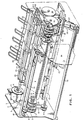
- a motor 1 capable of electronic control for operation at various speeds in both directions, such as a D.C. motor, is rigidly mounted to a left frame plate 2.
- a motor shaft position sensing assembly 3 such as a capacitive angular position sensing transducer, is mounted on one end of motor 1 to deliver to a system of control electronics (not shown) accurate information relative to the angular position and number of turns of the shaft 4 of motor 1.
- a motor drive pulley 5 which, in the preferred embodiment, has timing teeth to drive a timing belt 6 with no slippage.
- all belts and pulleys have timing teeth and it will be assumed that no slippage occurs relative to the belts and pulleys.
- Belt 6 drives a document drum drive pulley 7.
- Pulley 7 is pinned to a document drum drive shaft 8, and shaft 8 is pinned to a document drum 9 so that any angular movement of motor shaft 4 causes corresponding angular movement, according to the ratio of the diameters of pulleys 5 and 7, of drum 9.
- carrier lead screw pulley (not shown) which drives carrier lead screw belt 10 and carrier lead screw pulley 11.
- a carrier lead screw 12 is pinned to pulley 11 so that any angular movement of motor shaft 4 causes angular movement of lead screw 12 according to the ratios of the diameters of the two pairs of pulleys between motor shaft 4 and lead screw 12.
- a lead screw follower 13 is associated with the lead screw 12 to move left or right according to the rotation of lead screw 12.
- Lead screw follower 13 is rigidly attached to a printing or scanning carrier 14 to provide left or right movement of carrier 14 along frame rails 15 and 16 in accordance with lead screw motion.
- carrier 14 has mounted thereon a printing transducer 17 which may be selected from a number of printing technologies.
- printing technologies may include, but are not limited to, drop-on-demand ink jet printing, wire matrix printing, resistive, ribbon printing, and thermal printing.
- an appropriate light source and light sensitive detector assembly would be mounted on carrier 14 for translation relative to an intelligence bearing document mounted on drum 9. It will be understood by those skilled in the art that the choice of appropriate printing or scanning transducers is not a part of the paper handling system of this invention.
- a load dog clutch assembly 18 mounted concentric with and near the right end of drum shaft 8 is engageable with shaft 8 to turn gears 19 and 20 which rotate drive rollers to drive a sheet of paper to be loaded onto drum 9, as will be explained in detail hereinafter.
- An exit dog clutch assembly 21 is mounted concentric with shaft 8 just to the left of dog clutch assembly 18. The dog clutch assembly 21 is intermittently engaged relative to shaft 8 to drive belt 22 which turns paper exit rollers 23 for driving paper out of the system from drum 9, as will be explained in detail hereinafter.
- the clutches are engageable to turn gear 19 and to drive belt 22, respectively, one revolution after having been tripped and during counterclockwise rotation of shaft 8 relative to the right end of FIG. 1.
- Shaft 8 has mounted thereon single dog teeth associated with each of dog clutches 18 and 21.
- a load clutch latch lever 24 associated with dog clutch assembly 18 and an exit clutch latch lever 25 associated with dog clutch assembly 21 are separately pivotable about a shaft 26. Latch levers 24 and 25 are engaged and tripped by load clutch trip lever 27 and exit clutch trip lever 28, as will be described in more detail hereinafter. Trip levers 27 and 28 are mounted for movement along with movement of carrier 14.
- a pulley 29 is selectively engageable to shaft 8 through a spring clutch 30.
- the application of a radial force to the outside of spring clutch 30 toward the center of shaft 8 causes engagement of spring clutch 30 which drives pulley 29, belt 31, and pulley 32.
- a rotatable auxiliary shaft 33 is pinned to pulley 32.
- Pulley 34 is axially slidable along auxiliary shaft 33 but is angularly keyed to shaft 33.
- Pulley 36 has an axle (not shown) on carrier 14 and may be used to selectively impart rotational motion to carrier 14 for an auxiliary operation, for example escapement of an inked printing ribbon.
- a lever connected to a solenoid may be used to selectively engage clutch 30.
- FIG. 1 Also shown in FIG. 1 is a partial view of a paper cartridge 40 which is shown and described in greater detail hereinafter.
- FIG. 2 The rear perspective view of the system of this invention shown in FIG. 2 shows many of the aforementioned components of the system as were described relative to FIG. 1. For the purpose of clarity the same reference numerals are used for the elements described relative to FIG. 1.
- FIG. 2 a set of feed rollers 42 are shown which are pinned to a feed roller shaft 43.
- the feed roller shaft 43 is pinned to gear 20 so that rotation of rollers 42 occurs during the time of engagement of the load clutch 18, FIG. 1.
- a paper guide 41 is shown in FIG. 2, spaced from drum 9 by a suitable gap to maintain a document loaded onto drum 9 substantially in contact with the drum during the arc of the rotation enclosed by guide 41.
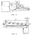
- FIG. 4 a sheet of paper 50 is shown clamped onto drum 9 by a plurality of spring loaded clamps 51. In their normal position, clamps 51 hold an edge of paper 50 onto the surface of drum 9. Clamps 51 may be simultaneously opened by rotation of a torque bar which runs the length of drum 9, inside the drum. An end of the torque bar is shown in FIG. 1 and is denoted by reference numeral 97.
- an actuation mechanism which will be described in more detail hereinafter is moved by a pin extending from gear 19 to engage the torque bar to rotate and provide for momentary opening of clamps 51.
- FIG. 4 shows, in an exaggerated manner, the skewed relationship of the edges of the rectangular sheet of paper 50 relative to the axis of drum 9.
- Carrier 14 is also shown schematically to be representative of any choice of printing or scanning technology.
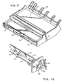
- FIG. 5 shows a more detailed view of the paper cartridge 40.
- Cartridge 40 is known in the paper handling art as a "corner buckling" cartridge in view of the paper corner retaining clips 44 which normally retain the paper in the cartridge.
- a spring loaded plate 45 upwardly biases the stack of papers 55. Clockwise engagement of feed rollers 42, FIG. 3, with the top sheet of papers 55 causes the exposed edge of the top sheet of sheets 55' to buckle upwardly as the sheet is driven out of the cartridge until the two corners release themselves from the retaining clips 44. After these corners are released the top sheet can continue to be fed onto drum 9 by further movement of feed rollers 42.
- Cartridge 40 also includes a paper stacking tray 47 and associated paper stacking extension rack 48 on which sheets of paper are supported after they are exited from the printing or scanning operation that occurs while the paper is clamped on drum 9.
- Cartridge 40 is so designed and mounted as to present the sheets of paper in a skewed way corresponding substantially to the skew of the sheet on the drum.
- FIGS..1, 2, and 3 the paper handling paths of the system are described. Looking from the right end of the drum back toward the left, counterclockwise rotation of drum 9 causes the print carrier 14 to traverse toward its first, rightmost, limit. Just before it reaches its rightmost limit feed rollers 42 are engaged to rotate one revolution in a clockwise direction. This drives the top sheet of paper in cartridge 40 out of cartridge 40 toward the drum as indicated by arrow 60 (FIG. 3). At this time, paper clamps 51 and the leading edge of the paper (not shown) being driven out of cartridge 40 are converging. At this convergence paper clamps 51 are opened against their normally self-closing spring tension.
- drum 9 When this convergence has continued to the point that the leading edge of the paper is positioned underneath the opened leading edges of paper clamps 51, rotation of drum 9 is reversed into a clockwise direction. Paper clamps 51 close upon this reversal and the paper is now engaged by paper clamps 51 to be wrapped around drum 9 and rotate in a clockwise direction as viewed from the nearest end of drum 9 shown in FIGS. 1-2.
- clockwise rotation of drum 9 carrier 14 traverses to the left (when viewed from FIG. 1, and away from the viewer with respect to FIG. 3), first to a joint where the printing or scanning operation will start, then to a second, leftmost, limit, where the printing or scanning operation ends.
- lever 95 mounted to shaft 94 can now engage lever 96 which is pivotable relative to the right end of drum 9.
- lever 96 is caused to rotate in a clockwise arc and engages tab 97 on torque bar 98.
- Torque bar 98 runs the length of drum 9 and has a plate 99 mounted thereto which engages paper clamps 51 to open paper clamps 51 upon counterclockwise rotation of bar 98.
- drum 9 has rotated counterclockwise and paper clamps 51 are open.
- a sheet of paper has been driven by feed rollers 42 far enough to have the leading edge thereof positioned under paper clamps 51.
- the rotation of drum 9 is now reversed so that drum 9 rotates clockwise as viewed from the right end of FIG. 1.
- the sheet of paper is now clamped onto drum 9.
- Clockwise rotation of drum 9 also reverses the direction of lead screw 12 and causes carrier 14 to traverse toward the left end of the paper handling system shown in FIG. 1.
- the assembly of trip levers 27 and 28 have progressed as far right as possible during operation of the paper handling system.
- the left side of trip lever 27 was positioned just to the right of latch lever 24.
- trip levers 27 and 28 are rotatable about pins 101 and 102, respectively.
- tabs 103 and 104 on trip levers 27 and 28, respectively interfere with the trip lever support 105 such that only clockwise rotation of trip lever 27 is possible and only counterclockwise rotation of trip lever 28 is possible.
- spring 106 biases both trip levers to the positions shown in FIG. 6.
- trip lever 27 rotates clockwise as it passes the load clutch latch lever 24 and does not trip, this latch lever during clockwise rotation of drum 9 with carrier 14 traversing to the left.
- this exit clutch latch lever is tripped relative to the exit dog clutch 21 to arm clutch 21 for paper unloading when drum rotation reverses again to a counterclockwise direction.
- both of the dog clutches 21 and 18 engage for driving the pulley or gear, respectively, connected thereto only when drum 9 is rotated in a counterclockwise direction and only for one revolution after these clutches have been tripped.
- carrier 14 With the paper loaded, the drum rotating clockwise and the exit clutch having been tripped as described above relative to FIG. 7, carrier 14 continues to traverse to the left during which time printing or scanning operations can occur. It will be understood by those skilled in the art that relatively high speed printing or scanning can take place because the drum is rotating continuously, without having to reverse direction, in a high speed manner relative to carrier 14 and the printing or scanning element 17 rigidly attached thereto, which also move continuously. Further, in view of the skewed mounting of the sheet of paper on drum 9, the carrier 14 can be continuously indexed with any requirement for movement only between printed lines. Various printing technologies can be employed such as resistive ribbon printing, wire matrix printing, and drop-on-demand inkjet printing, as examples.
- clutch 30 can be engaged to rotate pulley 29 relative to rotation of shaft 8 which, in turn, causes rotation of pulley 32, shaft 33, and pulleys 34. Belt 35 then transfers this rotation to pulley 36 mounted on carrier 14 which can be connected to a ribbon transport mechanism as will be understood by those skilled in the art.
- Clutch 30 can be an overrunning spring clutch to cause rotation of shaft 33 at any time that shaft 8 and drum 9 are rotated in a clockwise direction.
- clutch 30 can be a non-overrunning spring clutch selectively activated by an arm connected to an electromagnetic solenoid (not shown).
- the paper handling system can be operated to cause the paper document to be removed from drum 9 and stacked on the stacking tray 47 of cartridge 40.
- An optical sensor (not shown) on carrier 14 senses the passage of the trailing edge of the document mounted on drum 9. Clockwise rotation continues for approximately one-half of a rotation more at which time the direction of drum 9 is reversed for rotation in a counterclockwise direction. This delay in reversing the direction of rotation allows the trailing edge of the paper to be positioned at the lower right quadrant of drum 9 as viewed in FIG. 3 so that counterclockwise rotation of drum 9 allows the trailing edge of the paper to travel in a direction indicated by arrows 61 instead of jamming against other components of the paper handling system when rotation of drum is reversed.
- exit clutch 21 engages to drive pulley 110 (FIG. 1), belt 22, pulley 111, and exit roller shaft 112 in counterclockwise rotation as viewed from the right end of FIG. 1.
- this rotation of the exit roller shaft 112 causes exit rollers 23 to engage the trailing edge of the paper unwrapping from drum 9 and transports the paper toward the stacking tray 47 of cartridge 40.
- the speed ratio of rollers 23 relative to drum 9 is such that rollers 23 pull the paper out of the paper clamps 51 of drum 9 without the necessity of reopening these spring loaded paper clamps for paper removal.
- trip lever 28 rotates counterclockwise past the exit clutch latch lever 25 without tripping the latch lever.
- a single priority page of paper can be inserted into the rear of this paper handling system at any time immediately above the top sheet of paper in the cartridge 40 without clamping the leading edges of this page under the corner buckling clamps 44 of cartridge 40.
- the page entered in this priority manner will be the page fed to drum 9 rather than the top sheet in the cartridge.
- cam 120 pinned to shaft 43, causes a corresponding counterclockwise rotation in shaft 121 to which is connected a paper aligning gate 122.
- this counterclockwise rotation is caused by the engagement of pin 124 (on bell crank 123) with cam 120 during rotation of shaft 43.
- Bell crank 123 is pinned to shaft 121 and is normally biased to the position shown in FIG. 10 by spring 125.
- the initial position of the paper aligning gate 122 is down as shown in FIG.
- tabs 127 are a gating surface for the front edge of a priority sheet of paper to be loaded.
- Tabs 127 position the leading edge of a priority sheet over the top sheet of the stack of pages retained in the cartridge 40.
- the counterclockwise rotation of shaft 43 and the corresponding counterclockwise rotation of the paper aligning gate 122 removes the restraint provided by tabs 127 after their gating function ' has been provided, so that loading of the priority sheet can continue.
Landscapes
- Handling Of Cut Paper (AREA)
- Facsimile Scanning Arrangements (AREA)
- Character Spaces And Line Spaces In Printers (AREA)
- Feeding Of Articles By Means Other Than Belts Or Rollers (AREA)
Claims (10)
Applications Claiming Priority (2)
| Application Number | Priority Date | Filing Date | Title |
|---|---|---|---|
| US45165082A | 1982-12-20 | 1982-12-20 | |
| US451650 | 1995-05-26 |
Publications (3)
| Publication Number | Publication Date |
|---|---|
| EP0111667A2 EP0111667A2 (de) | 1984-06-27 |
| EP0111667A3 EP0111667A3 (en) | 1985-10-23 |
| EP0111667B1 true EP0111667B1 (de) | 1989-01-04 |
Family
ID=23793121
Family Applications (1)
| Application Number | Title | Priority Date | Filing Date |
|---|---|---|---|
| EP19830110303 Expired EP0111667B1 (de) | 1982-12-20 | 1983-10-17 | Hochgeschwindigkeitsdrucker |
Country Status (4)
| Country | Link |
|---|---|
| EP (1) | EP0111667B1 (de) |
| JP (1) | JPS59115879A (de) |
| CA (1) | CA1221871A (de) |
| DE (1) | DE3378820D1 (de) |
Family Cites Families (6)
| Publication number | Priority date | Publication date | Assignee | Title |
|---|---|---|---|---|
| FR1428363A (fr) * | 1964-03-13 | 1966-02-11 | Bosch Gmbh Robert | Procédé et dispositif pour l'impression d'un texte en clair |
| CH493889A (de) * | 1968-07-17 | 1970-07-15 | Zentronik Betr Karl Marx Stadt | Einrichtung zum Bearbeiten von Magnetkarten |
| GB1406482A (en) * | 1972-01-14 | 1975-09-17 | Marconi Co Ltd | Teleprinters |
| US4030588A (en) * | 1972-06-19 | 1977-06-21 | Canon Kabushiki Kaisha | Printer |
| DE3067272D1 (en) * | 1979-08-31 | 1984-05-03 | Xerox Corp | Methods of pre-collation copying |
| US4346880A (en) * | 1980-10-02 | 1982-08-31 | Xerox Corporation | Apparatus for inverting substrates |
-
1983
- 1983-10-05 CA CA000438443A patent/CA1221871A/en not_active Expired
- 1983-10-17 DE DE8383110303T patent/DE3378820D1/de not_active Expired
- 1983-10-17 EP EP19830110303 patent/EP0111667B1/de not_active Expired
- 1983-11-04 JP JP20606683A patent/JPS59115879A/ja active Pending
Also Published As
| Publication number | Publication date |
|---|---|
| EP0111667A3 (en) | 1985-10-23 |
| EP0111667A2 (de) | 1984-06-27 |
| JPS59115879A (ja) | 1984-07-04 |
| DE3378820D1 (en) | 1989-02-09 |
| CA1221871A (en) | 1987-05-19 |
Similar Documents
| Publication | Publication Date | Title |
|---|---|---|
| EP0529538B1 (de) | Blattführungsvorrichtung und Bilderzeugungssystem | |
| US4268021A (en) | Transportation arrangement for sheetlike recording carriers | |
| EP0580184B1 (de) | Drucker | |
| US6042109A (en) | Sheet feeding device with compact media path for paper-based and photographic media | |
| EP0111668B1 (de) | Verfahren zur beidseitigen Behandlung von Papierbögen | |
| EP0888895A2 (de) | Aufzeichnungsträgerhandhabung für beidseitiges Drucken | |
| US5124800A (en) | Apparatus for reading and recording image | |
| US4822019A (en) | Electronic equipment utilizing forward/reverse rotation of motor | |
| US5547183A (en) | Imaging device | |
| US4547783A (en) | Image forming apparatus | |
| US6463256B2 (en) | Duplexing module for printer | |
| EP0111667A2 (de) | Hochgeschwindigkeitsdrucker | |
| US6443446B1 (en) | Media transport mechanism for information transfer devices | |
| JP4444876B2 (ja) | 画像読取記録装置 | |
| JPS63134269A (ja) | カラ−記録方法および装置 | |
| JP3475561B2 (ja) | 小型プリンタ | |
| US7479976B2 (en) | Reversed thermal head printing | |
| JPS61291372A (ja) | プリンタ用の自動給紙装置 | |
| GB2297315A (en) | Removing skew from paper fed to a printer | |
| KR970005392Y1 (ko) | 열전사 기록장치 | |
| JPH0441267A (ja) | 熱転写記録装置 | |
| JP2710436B2 (ja) | 冊子状媒体用印字装置 | |
| JP3147958B2 (ja) | シート搬送装置 | |
| JPS6351230A (ja) | 記録装置 | |
| JPS6019625A (ja) | 記録装置 |
Legal Events
| Date | Code | Title | Description |
|---|---|---|---|
| PUAI | Public reference made under article 153(3) epc to a published international application that has entered the european phase |
Free format text: ORIGINAL CODE: 0009012 |
|
| AK | Designated contracting states |
Designated state(s): DE FR GB IT |
|
| 17P | Request for examination filed |
Effective date: 19841029 |
|
| PUAL | Search report despatched |
Free format text: ORIGINAL CODE: 0009013 |
|
| AK | Designated contracting states |
Designated state(s): DE FR GB IT |
|
| 17Q | First examination report despatched |
Effective date: 19861028 |
|
| R17C | First examination report despatched (corrected) |
Effective date: 19870626 |
|
| GRAA | (expected) grant |
Free format text: ORIGINAL CODE: 0009210 |
|
| AK | Designated contracting states |
Kind code of ref document: B1 Designated state(s): DE FR GB IT |
|
| REF | Corresponds to: |
Ref document number: 3378820 Country of ref document: DE Date of ref document: 19890209 |
|
| ET | Fr: translation filed | ||
| ITF | It: translation for a ep patent filed | ||
| PLBE | No opposition filed within time limit |
Free format text: ORIGINAL CODE: 0009261 |
|
| STAA | Information on the status of an ep patent application or granted ep patent |
Free format text: STATUS: NO OPPOSITION FILED WITHIN TIME LIMIT |
|
| 26N | No opposition filed | ||
| PGFP | Annual fee paid to national office [announced via postgrant information from national office to epo] |
Ref country code: GB Payment date: 19910923 Year of fee payment: 9 |
|
| PGFP | Annual fee paid to national office [announced via postgrant information from national office to epo] |
Ref country code: FR Payment date: 19911001 Year of fee payment: 9 |
|
| ITTA | It: last paid annual fee | ||
| PGFP | Annual fee paid to national office [announced via postgrant information from national office to epo] |
Ref country code: DE Payment date: 19911102 Year of fee payment: 9 |
|
| PG25 | Lapsed in a contracting state [announced via postgrant information from national office to epo] |
Ref country code: GB Effective date: 19921017 |
|
| GBPC | Gb: european patent ceased through non-payment of renewal fee |
Effective date: 19921017 |
|
| PG25 | Lapsed in a contracting state [announced via postgrant information from national office to epo] |
Ref country code: FR Effective date: 19930630 |
|
| PG25 | Lapsed in a contracting state [announced via postgrant information from national office to epo] |
Ref country code: DE Effective date: 19930701 |
|
| REG | Reference to a national code |
Ref country code: FR Ref legal event code: ST |