EP0111782A2 - Turbosuflante avec un élément rétenteur pour fixer la roue du compresseur sur l'axe - Google Patents
Turbosuflante avec un élément rétenteur pour fixer la roue du compresseur sur l'axe Download PDFInfo
- Publication number
- EP0111782A2 EP0111782A2 EP83111915A EP83111915A EP0111782A2 EP 0111782 A2 EP0111782 A2 EP 0111782A2 EP 83111915 A EP83111915 A EP 83111915A EP 83111915 A EP83111915 A EP 83111915A EP 0111782 A2 EP0111782 A2 EP 0111782A2
- Authority
- EP
- European Patent Office
- Prior art keywords
- shaft
- sleeve
- compressor
- compressor rotor
- rotor
- Prior art date
- Legal status (The legal status is an assumption and is not a legal conclusion. Google has not performed a legal analysis and makes no representation as to the accuracy of the status listed.)
- Granted
Links
Images

Classifications
-
- F—MECHANICAL ENGINEERING; LIGHTING; HEATING; WEAPONS; BLASTING
- F01—MACHINES OR ENGINES IN GENERAL; ENGINE PLANTS IN GENERAL; STEAM ENGINES
- F01D—NON-POSITIVE DISPLACEMENT MACHINES OR ENGINES, e.g. STEAM TURBINES
- F01D5/00—Blades; Blade-carrying members; Heating, heat-insulating, cooling or antivibration means on the blades or the members
- F01D5/02—Blade-carrying members, e.g. rotors
- F01D5/025—Fixing blade carrying members on shafts
-
- F—MECHANICAL ENGINEERING; LIGHTING; HEATING; WEAPONS; BLASTING
- F04—POSITIVE - DISPLACEMENT MACHINES FOR LIQUIDS; PUMPS FOR LIQUIDS OR ELASTIC FLUIDS
- F04D—NON-POSITIVE-DISPLACEMENT PUMPS
- F04D29/00—Details, component parts, or accessories
- F04D29/26—Rotors specially for elastic fluids
- F04D29/266—Rotors specially for elastic fluids mounting compressor rotors on shafts
-
- F—MECHANICAL ENGINEERING; LIGHTING; HEATING; WEAPONS; BLASTING
- F16—ENGINEERING ELEMENTS AND UNITS; GENERAL MEASURES FOR PRODUCING AND MAINTAINING EFFECTIVE FUNCTIONING OF MACHINES OR INSTALLATIONS; THERMAL INSULATION IN GENERAL
- F16D—COUPLINGS FOR TRANSMITTING ROTATION; CLUTCHES; BRAKES
- F16D1/00—Couplings for rigidly connecting two coaxial shafts or other movable machine elements
- F16D1/06—Couplings for rigidly connecting two coaxial shafts or other movable machine elements for attachment of a member on a shaft or on a shaft-end
-
- F—MECHANICAL ENGINEERING; LIGHTING; HEATING; WEAPONS; BLASTING
- F16—ENGINEERING ELEMENTS AND UNITS; GENERAL MEASURES FOR PRODUCING AND MAINTAINING EFFECTIVE FUNCTIONING OF MACHINES OR INSTALLATIONS; THERMAL INSULATION IN GENERAL
- F16C—SHAFTS; FLEXIBLE SHAFTS; ELEMENTS OR CRANKSHAFT MECHANISMS; ROTARY BODIES OTHER THAN GEARING ELEMENTS; BEARINGS
- F16C2360/00—Engines or pumps
- F16C2360/23—Gas turbine engines
- F16C2360/24—Turbochargers
Definitions
- turbomachinery e.g. a turbocharger, a turbojet or a turbofan engine
- turbomachinery comprising a compressor rotor mounted for rotation on a compressor shaft, a retainer for securing the compressor rotor to the compressor shaft, wherein the compressor rotor has an aperture therethrough for receiving the compressor shaft therein.
- turbomachinery as mentioned above is improved by a retaining sleeve having a bore therethrough for mounting said sleeve onto said shaft adjacent the compressor rotor, said sleeve bore having a diameter to form an interference fit over the shaft such that the sleeve alone prevents axial movement of the compressor rotor on the shaft in the direction of the sleeve, said sleeve having an engagement surface for engaging said compressor rotor to transmit torque from said shaft to said compressor rotor through said retaining sleeve.
- the compressor rotor is mounted on the shaft by pressing a retainer sleeve onto the shaft with minimal engagement between the nut and the rotor to transmit torque from the shaft to the rotor by way of the press-on of the sleeve with the shaft and its engagement with the rotor.
- the turbomachinery may further comprise a spring means positioned between said retaining sleeve and the compressor rotor for applying a force between the compressor and said retaining sleeve for maintaining an axial force on the compressor rotor.
- the spring means is a Belville spring. The spring means maintain an engagement force between the retainer sleeve and the compressor rotor even if in operation of the turbomachinery contractions or expansions in the shaft or the compressor rotor should occur.
- the sleeve may be formed with threads around the outer circumference so that an internally threaded tool can be brought into engagement with the sleeve for mounting or removal.
- the shaft may be hardened to facilitate retentinon of the retaining sleeve thereon but to permit removal of the sleeve without damage to the shaft.
- FIGURE 1 is a perspective view of a turbocharger 20 embodying the present invention.
- the turbocharger includes an outer structure 22 consisting of a compressor housing unit 24 coupled to a turbine housing unit 26 by a V-clamp band 28.
- compressor housing unit 24 includes a tubular inlet port 40 with a transverse wall 42 attached to one end of port 40 and extending outwardly therefrom.
- a circumferential chamber 44 is attached from wall 42.
- Inlet port 40 defines a compressor air inlet 50 and circumferential chamber 44 defines a compressor exhaust 52.
- Turbine housing 26 defines a turbine air inlet 54 and a turbine exhaust 56.
- turbocharger air is drawn into inlet 50 and compressed air is discharged from exhaust 52 to an internal combustion engine to which the turbocharger is mounted. Exhaust air from the engine is channeled into turbine air inlet 54 to drive the turbocharger turbine and is exhausted through turbine exhaust 56.
- a bearing support cylinder 60 is mounted within inlet port 40 by a plurality of vanes 62 extending from the inside wall surface 64 of inlet port 40.
- a cap 66 is mounted over the end of support cylinder 60.
- a piston type actuator 80 is mounted by bracket 82 (FIGURE 1) to turbine housing 26.
- Actuator 80 includes a controller 84 operated to extend and retract control rod 86 as will be discussed hereinafter in greater detail. Air lines 88 and 89. provide air to controller 84 as necessary to operate rod 86.
- An oil reservoir cover plate 90 is attached to compressor housing unit 24 by a plurality of screws 92.
- compressor housing unit 24 includes a tubular inlet port 40 with a transverse wall 42 attached to one end thereof to one of the inlet ports and extending outwardly therefrom.
- a circumferential chamber 44 is attached to the end of wall 42 remote from inlet port 40 and has a varying area around its circumference increasing to the discharge provided by compressor exhaust 52 (FIGURE 1).
- Inlet port 40 has a first inside wall portion 110 having a converging diameter toward wall 42 and a second inside wall portion 112 joined to first inside wall portion 110 by a step 114.
- the second inside wall portion 112 has a diverging diameter toward wall 42.
- Wall 42 has a plurality of circumferentially spaced apertures 116 therethrough.
- Chamber 44 has an opening 118 substantially in the plane of wall 42 in addition to compressor exhaust 52.
- a forward compressor wall insert 126 includes a tubular throat 128 and a circular disc 130 attached transversely from one end of throat 128.
- Throat 128 has an inside wall surface 131 having a diameter converging toward disc 130 and an outer surface 132 having a diameter diverging toward disc 130.
- the diverging diameter surface 132 corresponds to the diverging surface of inside wall portion 112 of inlet port 40 such that throat 128 may be inserted within and mated with inlet port 40.
- the converging diameter inside wall surface 131 of throat 128 corresponds to the extension of converging diameter of first inside wall portion 110 of inlet port 40.
- a plurality of rivet-like protrusions 140 extend from disc 130 and correspond to apertures 116 in wall 42. With the insert engaged to compressor housing 24 with the end of throat 128 engaging step l14 of inlet port 40, protrusions 140 are engaged through apertures 116 with disc 130 abutting the corresponding surface of wall 42. As is shown in FIGURE 2, protrusions 140 have been inserted into apertures 116 and the heads thereof deformed to attach insert 126 to housing 24. Disc 130 extends beyond wall 42 to partially cover opening 118 of chamber 44. A circumferential gap 146 is formed between the outer tip of disc 130 and the wall of chamber 44, and a diffuser area 148 is formed between disc 130 and compressor backwall 100 between centrifugal flow compressor rotor 172 and gap 146 leading to chamber 44.
- bearing support cylinder 60 is supported concentrically within inlet port 40 by a plurality of vanes 62 extending inwardly from wall surface 64 of port 40.
- Turbocharger 20 further includes a shaft 160 supported for rotation in bearing support cylinder 60 by two ball bearing assemblies 162 and 164.
- a radial flow turbine rotor 170 is mounted at one end of shaft 160 and a centrifugal flow compressor rotor 172 is mounted intermediate of turbine rotor 170 and bearing assemblies 162 and 164.
- Shaft 160 passes through aperture 176 in compressor backwall 100 and labyrinth seal 174 in turbine backwall 102.
- Turbine rotor 170 is fixedly attached to shaft 160, such as by welding, and compressor rotor 172 is retained in position on shaft 160-by retainer nut 180.
- Compressor rotor 172 is drilled to receive shaft 160 and counterbored to form a bore 182.
- Bore 182 has a diameter larger than the outer diameter of retainer nut 180 such that retainer nut 180 may be pressed onto shaft 160 into engagement with the botom wall 184 of bore 182 to retain the compressor rotor in position on shaft 160.
- a compressor rotor shim 186 is positioned between compressor rotor 172 and a step 188 in shaft 160 to accurately position the compressor rotor in the axial direction.
- a ring 200 is fitted within the end of cylinder 60 adjacent compressor rotor 172 and is prevented from moving into cylinder 60 by a retaining ring 202 attached to cylinder 60.
- Outer raceway 204 of bearing assembly 164 is formed in ring 200, the inner raceway 206 being integrally formed in shaft 160.
- Balls 208 are engaged between the inner and outer raceways to form bearing assembly 164.
- Bearing assembly 162 includes inner raceway 210 formed integrally in shaft 160 and an outer ring 212 slidable within cylinder 60 with an outer raceway 214 formed therein for receiving balls 216.
- a compression spring 218 is engaged between ring 212 and a retaining ring 220 fixed within cylinder 60 and biases ring 212 outwardly to fix the position of balls 216 and 208 in bearing assemblies 162 and 164, respectively, thereby fixing the position of shaft 160.
- the outer raceway 204 is formed in ring 200 with the ball radius on only one side.
- the assembly of bearing assembly 164 is made by positioning a full complement of balls 208 in raceway 206, and engaging ring 200 therearound.
- outer raceway 214 is formed in ring 212 with the ball radius on only one side.
- Balls 216 of bearing assembly 162 are assembled by moving outer ring 212 to compress spring 218 and inserting a full complement of balls 216 in raceway 214 of shaft 160. By releasing ring 212, spring 218 automatically forces the ring into engagement with balls 216 to form bearing assembly 162 while simultaneously engaging ring 200 against balls 208 of bearing assembly 164.
- bearing assemblies 162 and 164 may be used in bearing assemblies 162 and 164 by the use of an appropriate retainer.
- an oil impregnated retainer or a sacrificial retainer which replenishes a self-lubricating coating to the balls may be used.
- the mounting of shaft 160 within cylinder 60 is completed by the engagement of cap 66 on the end of cylinder 60 to close the opening in cylinder 60 remote from compressor rotor 172.
- the use in the present bearing system of the ball bearing arrangement employing integral inner raceways permits a larger diameter shaft and thus provides a very "stiff" shaft. Additionally, this bearing arrangement provides a very tight bearing system permitting very little radial or axial movement. As a result, the present bearing system substantially reduces the clearance required between the compressor and turbine and surrounding housing, and concentricity problems are minimized.
- bearing assemblies 162 and 164 are "starved" of oil.
- the only lubrication provided to the bearing assemblies is through wicks 222'and 224 which transfer oil from a reservoir R by capillary action to ramps or slingers 226. Oil supplied to slingers 226 is projected by centrifugal force to bearing assemblies 162 and 164 during rotation of shaft 160.
- the bearing assemblies may be permanently lubricated with a heavy consistency oil or grease which is packed into the raceways and around the balls of the bearing assemblies.
- an oil impregnated phenolic retainer may be used to provide lubricant to the balls for a considerable period. In either of these cases, the need for wicks 222 and 224 and slingers 226 would be eliminated although with a reduced bearing life.
- journal and disc bearings of conventional turbochargers are replaced by the more precise ball type bearing assemblies, thereby eliminating the need for a continuous flow of lubrication for the bearings.
- both the compressor and the turbine of the present turbocharger are overhung to one side of the bearing assemblies, and the turbine is maximally removed from the bearing assemblies with the compressor positioned between the bearing assemblies and the turbine. As this arrangement provides sufficient thermal insulation between the turbine and the bearing assemblies, the bearings will not be sufficiently heated as to require conventional lubrication methods.
- the back to back compressor/turbine arrangement of the present invention not only reduces substanstantially the heat conducted to the bearing assemblies but also minimizes the thermal expansion effects, thereby lowering the blade tip clearances required.
- This arrangement further eliminates the conventional bearing housing and provides a more compact package than present straddle mounted rotors having the support bearings intermediate of the compressor and turbine.
- antifriction ball bearing assemblies 162 and 164 provides much better control over the radial and axial movement of the compressor and turbine, thereby allowing reduced blade tip clearance. This in turn appreciably improves the compressor and turbine efficiency.
- the use of the antifriction ball bearing assemblies 162 and 164 also reduces the turbine work required to drive the bearings. This in turn reduces the engine back pressure resulting in the improvement of the specific fuel consumption as well as enhancing the ability to accelerate the rotor.
- the present turbocharger is also provided with a nozzle area control structure 228 for selectively varying the turbine nozzle area to control the speed or pressure output of the turbocharger.
- a nozzle area control structure 228 for selectively varying the turbine nozzle area to control the speed or pressure output of the turbocharger.
- exhaust gas from the internal combustion engine on which the turbocharger is mounted is injected into the turbocharger through turbine air inlet 54 and channeled against the blades of turbine rotor 170 through a nozzle area 230 formed by turbine backwall 102, a wall 232 parallel thereto f and the nozzle vanes 234.
- This nozzle area is controlled by structure 228 including a plurality of movable nozzle vanes 234 positioned circumferentially about the nozzle area and rotatable to vary flow velocity and amgle of exhaust gas to turbine rotor 170.
- vanes 234 include trunnions 236 and 238 extending from opposite sides thereof. Trunnion 236 extends through turbine backwall 102 and is attached to actuation lever 240. Trunnion 238 extends into wall 232.
- a nipple 242 is formed on one end of each actuation lever. These nipples extend into radial slots 244 formed in a control ring 246. Control ring 246 and actuation levers 240 are situated in air space gap 247 intermediate of compressor rotor 172 and turbine rotor 170. Control ring 246 is concentrically positioned about the axis of shaft 160 and is received on a cylindrical surface 248 extending from compressor backwall 100.
- the control ring 246 includes an inner ring 250 and an outer ring 252 formed with an inner and outer raceway, respectively, for receiving a plurality of balls 254 therebetween.
- Inner ring 250 is fixedly attached to the cylindrical surface 248 extending from compressor backwall 100, and outer ring 252 rotates angularly relative to the inner ring.
- outer ring 252 rotates angularly relative to the inner ring.
- each of the actuation levers 240 is rotated about the axes of trunnions 236 and 238, resulting in the simultaneous rotation of each nozzle vane 234.
- One of the actuation levers 240 is provided with an extension 262.
- Control rod 86 is attached to the end of extension 262 remote from nipple 242. By the movement of control rod 86, actuation lever 240 is pivoted to angularly rotate outer ring 252 of control ring 246 thereby rotating each of the other actuation levers 240 and nozzle vanes 234 attached thereto.
- Controller 84 is designed to extend control rod 86 to open nozzle vanes 234 to turbine rotor 170 at low and high manifold pressures and to retract control rod 86 to close these nozzle vanes at intermediate pressures. More specifically, while operating at a closed throttle position where the intake manifold is under a vacuum condition, for example with manifold pressures of 5 to 8 pounds per square inch absolute, the controller operates to extend rod 86 to open nozzle vanes 234 permitting the engine to operate with as little back pressure as possible.
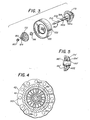
- FIGURE 3 illustrates compressor rotor 172 and retainer nut 180 separated from turbine rotor 170 and compressor-turbine shaft 160.
- turbine rotor 170 is attached to one end of shaft 160, such as by welding or other suitable permanent attachment means.
- the shaft prior to its attachment to turbine rotor 170, is formed with an enlarged bearing surface 160a, and a step 188 to a narrower diameter shaft portion 160b.
- raceways 206 and 210 are formed directly in shaft 160.
- shaft 160 is inserted through apertures in compressor backwall 100 and turbine backwall 102.
- Shim 186 is positioned over shaft 160 into engagement with step 188 on shaft 160.
- Compressor rotor 172 is engaged over shaft 160 and rests on shaft portion 160b.
- Retainer nut 18 0 is then pressed onto portion 160b into bore 182 of compressor rotor 172 and into engagement with bottom wall 184 of bore 182.
- Nut 180 consists of a sleeve having a smooth inner bore 180a therethrough. The bore through nut 180 forms an interference fit with portion 160b of shaft 160.
- the interference in one embodiment of the invention, is on the order of .001 of an inch.
- the shaft must be heat treated to extremely high degrees of hardness.
- the present retaining sleeve secures compressor rotor 172 to shaft 160 without necessitating the grinding or cutting of threads into the hardened shaft.-
- the cost and problems associated with forming threads on a heat treated shaft are eliminated.
- the retaining nut 180 may be pressed onto the shaft and withdrawn without damage to the shaft surface.
- nut 180 is formed with threads around the outer facing surface thereof.
- Bore 182 is of a sufficient diameter as to provide a gap 420 (FIGURE 4) between bore 182 and the threads on the outer surface of nut 180. This gap permits the insertion of an appropriate internally threaded tool for withdrawing the nut from the shaft for removal of the compressor rotor.
- a spring device may be required between the retainer nut and the compressor rotor to maintain an axial force on the compressor rotor during expansion and contraction of components of the turbocharger.
- the retainer nut of the present invention does not have the capability of developing high compressive loading in the compressor rotor or tension in the compressor-turbine shaft when mounted in position. Therefore, in the alternative embodiment illustrated in FIGURE 5, a cone shape or Belville spring 422 is inserted between the retainer nut 180 and the compressor rotor 172.
- FIGURE 5 Because the components in the embodiment illustrated in FIGURE 5 are identical or correspond to elements in the embodiment illustrated in FIGURES 2 and 3-4, the same numeral, with the designation prime (') will be used to identify like or corresponding parts to those in the embodiment illustrated in FIGURES 2 and 3-4.
- shaft 160' is engaged through compressor rotor 172'.
- Retainer nut 180' is engaged over the end of shaft 160' with Belville spring 422 mounted on shaft 160' between nut 180' and wall 184' of bore 182' in compressor rotor 172'.
- Belville spring 422 is initially compressed as retainer nut 180' is mounted on shaft 160'.
Landscapes
- Engineering & Computer Science (AREA)
- General Engineering & Computer Science (AREA)
- Mechanical Engineering (AREA)
- Supercharger (AREA)
Priority Applications (1)
| Application Number | Priority Date | Filing Date | Title |
|---|---|---|---|
| EP19830111915 EP0111782B1 (fr) | 1979-05-14 | 1979-05-14 | Turbosuflante avec un élément rétenteur pour fixer la roue du compresseur sur l'axe |
Applications Claiming Priority (1)
| Application Number | Priority Date | Filing Date | Title |
|---|---|---|---|
| EP19830111915 EP0111782B1 (fr) | 1979-05-14 | 1979-05-14 | Turbosuflante avec un élément rétenteur pour fixer la roue du compresseur sur l'axe |
Related Parent Applications (1)
| Application Number | Title | Priority Date | Filing Date |
|---|---|---|---|
| EP79901419.6 Division | 1980-12-01 |
Publications (3)
| Publication Number | Publication Date |
|---|---|
| EP0111782A2 true EP0111782A2 (fr) | 1984-06-27 |
| EP0111782A3 EP0111782A3 (en) | 1984-11-28 |
| EP0111782B1 EP0111782B1 (fr) | 1988-08-10 |
Family
ID=8190834
Family Applications (1)
| Application Number | Title | Priority Date | Filing Date |
|---|---|---|---|
| EP19830111915 Expired EP0111782B1 (fr) | 1979-05-14 | 1979-05-14 | Turbosuflante avec un élément rétenteur pour fixer la roue du compresseur sur l'axe |
Country Status (1)
| Country | Link |
|---|---|
| EP (1) | EP0111782B1 (fr) |
Cited By (1)
| Publication number | Priority date | Publication date | Assignee | Title |
|---|---|---|---|---|
| WO2007009766A1 (fr) * | 2005-07-20 | 2007-01-25 | Gardner Denver Schopfheim Gmbh | Compresseur radial |
Families Citing this family (1)
| Publication number | Priority date | Publication date | Assignee | Title |
|---|---|---|---|---|
| DE102018008934A1 (de) | 2018-11-12 | 2020-05-14 | Daimler Ag | Befestigungsanordnung eines Verdichterrads an einer Welle eines Abgasturboladers, insbesondere für ein Kraftfahrzeug |
Family Cites Families (6)
| Publication number | Priority date | Publication date | Assignee | Title |
|---|---|---|---|---|
| FR613632A (fr) * | 1925-05-22 | 1926-11-25 | Anciens Ets Skoda | Dispositif de fixation élastique de roues sur des arbres, notamment de rotors de turbines |
| DE1017320B (de) * | 1953-09-21 | 1957-10-10 | Maschf Augsburg Nuernberg Ag | Befestigung eines auf der Welle fliegend angeordneten Laufrades von Kreiselradmaschinen |
| GB770004A (en) * | 1954-05-11 | 1957-03-13 | Rover Co Ltd | Means for mounting a rotor on a shaft |
| DE1036273B (de) * | 1955-12-21 | 1958-08-14 | Kopp & Kausch | Befestigung eines fliegend angeordneten Turbomaschinen-Laufrades auf der Welle |
| GB1312528A (en) * | 1970-09-05 | 1973-04-04 | Concentric Pumps Ltd | Coolant pumps for internal combustion engines |
| DE2457231C2 (de) * | 1974-12-04 | 1976-11-25 | Motoren Turbinen Union | Laufrad fuer eine schnellaufende turbomaschine |
-
1979
- 1979-05-14 EP EP19830111915 patent/EP0111782B1/fr not_active Expired
Cited By (1)
| Publication number | Priority date | Publication date | Assignee | Title |
|---|---|---|---|---|
| WO2007009766A1 (fr) * | 2005-07-20 | 2007-01-25 | Gardner Denver Schopfheim Gmbh | Compresseur radial |
Also Published As
| Publication number | Publication date |
|---|---|
| EP0111782A3 (en) | 1984-11-28 |
| EP0111782B1 (fr) | 1988-08-10 |
Similar Documents
| Publication | Publication Date | Title |
|---|---|---|
| EP3719265B1 (fr) | Joint de segment de piston rotatif en carbone | |
| US4179247A (en) | Turbocharger having variable area turbine nozzles | |
| EP1724445B1 (fr) | Dispositif pour l'évacuation de l'huile de graissage | |
| US4358253A (en) | Turbocharger for use in an internal combustion engine | |
| US8186886B2 (en) | Turbocharger shaft bearing system | |
| US7371011B2 (en) | Turbocharger shaft bearing system | |
| EP1740807B1 (fr) | Turbocompresseur avec paliers à feuille hydrodynamiques | |
| US7677041B2 (en) | Bearing systems for high-speed rotating machinery | |
| EP2208903B1 (fr) | Palier et mécanismes de rétention | |
| US10669882B2 (en) | Variable stator blade operating device | |
| US4482303A (en) | Turbo-compressor apparatus | |
| GB2564537A (en) | Fan module with variable-pitch blades | |
| US11199103B2 (en) | Seal assembly for a turbomachine | |
| EP0030230B2 (fr) | Turbochargeur utilise dans un moteur a combustion interne ou turboreacteur | |
| US4353685A (en) | Turbocharger compressor rotor retainer | |
| CN112345243B (zh) | 一种滚动轴承超低温工况环境模拟装置 | |
| US20030072509A1 (en) | Bearing system for high-speed rotating machinery | |
| EP1988256A2 (fr) | Joints, systèmes étanches et procédés pour étanchéifier un arbre | |
| EP0111782A2 (fr) | Turbosuflante avec un élément rétenteur pour fixer la roue du compresseur sur l'axe | |
| EP3835606A1 (fr) | Ressort de centrage incurvé pour un palier de butée | |
| EP0121670B1 (fr) | Dispositif de roulement | |
| EP0111781B1 (fr) | Dispositif de contrôle pour turbosuflante | |
| EP4060209B1 (fr) | Système de joint de carbone d'autoguidage | |
| EP0185515A1 (fr) | Agencement et système de montage pour le rotor d'une turbosoufflante | |
| EP0122328B1 (fr) | Carter de compresseur pour une turbosoufflante ainsi que méthode de production d'un tel carter |
Legal Events
| Date | Code | Title | Description |
|---|---|---|---|
| PUAI | Public reference made under article 153(3) epc to a published international application that has entered the european phase |
Free format text: ORIGINAL CODE: 0009012 |
|
| AC | Divisional application: reference to earlier application |
Ref document number: 30230 Country of ref document: EP |
|
| AK | Designated contracting states |
Designated state(s): DE FR |
|
| PUAL | Search report despatched |
Free format text: ORIGINAL CODE: 0009013 |
|
| RHK1 | Main classification (correction) |
Ipc: F04D 29/20 |
|
| AK | Designated contracting states |
Designated state(s): DE FR |
|
| 17P | Request for examination filed |
Effective date: 19850419 |
|
| GRAA | (expected) grant |
Free format text: ORIGINAL CODE: 0009210 |
|
| AC | Divisional application: reference to earlier application |
Ref document number: 30230 Country of ref document: EP |
|
| AK | Designated contracting states |
Kind code of ref document: B1 Designated state(s): DE FR |
|
| REF | Corresponds to: |
Ref document number: 2967680 Country of ref document: DE Date of ref document: 19880915 |
|
| ET | Fr: translation filed | ||
| PLBE | No opposition filed within time limit |
Free format text: ORIGINAL CODE: 0009261 |
|
| STAA | Information on the status of an ep patent application or granted ep patent |
Free format text: STATUS: NO OPPOSITION FILED WITHIN TIME LIMIT |
|
| 26N | No opposition filed | ||
| PGFP | Annual fee paid to national office [announced via postgrant information from national office to epo] |
Ref country code: FR Payment date: 19920511 Year of fee payment: 14 |
|
| PG25 | Lapsed in a contracting state [announced via postgrant information from national office to epo] |
Ref country code: FR Effective date: 19940131 |
|
| REG | Reference to a national code |
Ref country code: FR Ref legal event code: ST |
|
| PGFP | Annual fee paid to national office [announced via postgrant information from national office to epo] |
Ref country code: DE Payment date: 19950511 Year of fee payment: 17 |
|
| PG25 | Lapsed in a contracting state [announced via postgrant information from national office to epo] |
Ref country code: DE Effective date: 19970201 |