EP0111865A2 - Laminoir à vitesses circonférentielles différentes - Google Patents
Laminoir à vitesses circonférentielles différentes Download PDFInfo
- Publication number
- EP0111865A2 EP0111865A2 EP83112482A EP83112482A EP0111865A2 EP 0111865 A2 EP0111865 A2 EP 0111865A2 EP 83112482 A EP83112482 A EP 83112482A EP 83112482 A EP83112482 A EP 83112482A EP 0111865 A2 EP0111865 A2 EP 0111865A2
- Authority
- EP
- European Patent Office
- Prior art keywords
- rolling
- strip
- tension
- roll
- rolls
- Prior art date
- Legal status (The legal status is an assumption and is not a legal conclusion. Google has not performed a legal analysis and makes no representation as to the accuracy of the status listed.)
- Withdrawn
Links
- 238000005096 rolling process Methods 0.000 title claims abstract description 271
- 230000007423 decrease Effects 0.000 claims abstract description 4
- 230000009467 reduction Effects 0.000 description 24
- 238000004519 manufacturing process Methods 0.000 description 6
- 239000002826 coolant Substances 0.000 description 5
- 230000000694 effects Effects 0.000 description 5
- 238000000137 annealing Methods 0.000 description 4
- 238000005097 cold rolling Methods 0.000 description 4
- 238000010276 construction Methods 0.000 description 4
- 238000000034 method Methods 0.000 description 4
- 230000003247 decreasing effect Effects 0.000 description 3
- 239000003921 oil Substances 0.000 description 3
- 238000004804 winding Methods 0.000 description 3
- 230000008901 benefit Effects 0.000 description 2
- 230000007547 defect Effects 0.000 description 2
- 230000010354 integration Effects 0.000 description 2
- 239000000463 material Substances 0.000 description 2
- 230000007935 neutral effect Effects 0.000 description 2
- 239000007921 spray Substances 0.000 description 2
- 229910001209 Low-carbon steel Inorganic materials 0.000 description 1
- 229910000831 Steel Inorganic materials 0.000 description 1
- 230000001133 acceleration Effects 0.000 description 1
- 235000015278 beef Nutrition 0.000 description 1
- 238000004140 cleaning Methods 0.000 description 1
- 238000001816 cooling Methods 0.000 description 1
- 238000009826 distribution Methods 0.000 description 1
- 238000002474 experimental method Methods 0.000 description 1
- 239000012530 fluid Substances 0.000 description 1
- 238000009434 installation Methods 0.000 description 1
- 238000005461 lubrication Methods 0.000 description 1
- 239000002480 mineral oil Substances 0.000 description 1
- 235000010446 mineral oil Nutrition 0.000 description 1
- 238000012806 monitoring device Methods 0.000 description 1
- 238000009877 rendering Methods 0.000 description 1
- 238000010008 shearing Methods 0.000 description 1
- 238000005507 spraying Methods 0.000 description 1
- 239000010959 steel Substances 0.000 description 1
- 239000003760 tallow Substances 0.000 description 1
Images


Classifications
-
- B—PERFORMING OPERATIONS; TRANSPORTING
- B21—MECHANICAL METAL-WORKING WITHOUT ESSENTIALLY REMOVING MATERIAL; PUNCHING METAL
- B21B—ROLLING OF METAL
- B21B1/00—Metal-rolling methods or mills for making semi-finished products of solid or profiled cross-section; Sequence of operations in milling trains; Layout of rolling-mill plant, e.g. grouping of stands; Succession of passes or of sectional pass alternations
- B21B1/22—Metal-rolling methods or mills for making semi-finished products of solid or profiled cross-section; Sequence of operations in milling trains; Layout of rolling-mill plant, e.g. grouping of stands; Succession of passes or of sectional pass alternations for rolling plates, strips, bands or sheets of indefinite length
- B21B1/222—Metal-rolling methods or mills for making semi-finished products of solid or profiled cross-section; Sequence of operations in milling trains; Layout of rolling-mill plant, e.g. grouping of stands; Succession of passes or of sectional pass alternations for rolling plates, strips, bands or sheets of indefinite length in a rolling-drawing process; in a multi-pass mill
-
- B—PERFORMING OPERATIONS; TRANSPORTING
- B21—MECHANICAL METAL-WORKING WITHOUT ESSENTIALLY REMOVING MATERIAL; PUNCHING METAL
- B21B—ROLLING OF METAL
- B21B1/00—Metal-rolling methods or mills for making semi-finished products of solid or profiled cross-section; Sequence of operations in milling trains; Layout of rolling-mill plant, e.g. grouping of stands; Succession of passes or of sectional pass alternations
- B21B1/22—Metal-rolling methods or mills for making semi-finished products of solid or profiled cross-section; Sequence of operations in milling trains; Layout of rolling-mill plant, e.g. grouping of stands; Succession of passes or of sectional pass alternations for rolling plates, strips, bands or sheets of indefinite length
Definitions
- This invention relates to different circumferential speed continuous rolling mill capable of increasing the rolling reduction.
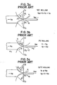
- F ig. 1 shows a four-high rolling mill (hereinafter 4H mill) typical of rolling mills of the prior art.
- the 4H mill comprises upper and lower working rolls 1 and 2 supported by backing-up rolls 4 and 5 respectively to perform rolling between the upper and lower working rolls .1 and 2.
- the 4H mill further comprises other expensive equipment, including a roll stand, a screw-down device, a roll drive, etc.
- an additional working roll were used with a 4H mill to enable rolling simultaneously at two rolling points as shown in Fig. 2, excellent economic effects could be achieved.
- there is some snag which stands in the way of realizing benefits from use of an additional roll for the aforesaid purpose.
- the working rolls 1 and 2 or 2 and 3 which form a set have the same circumfernetial speed which is substantially equal to the delivery speed of a rolled strip and the entering speed of the roller strip is lower than the circumferential speed of the rolls by a magnitude substantially corresponding to the rolling reduction rate y.
- circumferential speeds v 1 , v 2 and v 3 of the upper and lower working rolls 1, 2 and 3 respectively are equal to one another.
- a strip to be rolled 10 by the working rolls 1 and 2 has a speed v s2 which has the following relation:
- the rolled strip 10 introduced to between the working rolls 2 and 3 has a speed v s2 ' which has the following relation:
- v s2 ' ⁇ v s2 and the rolled strip 10 will have a loop at the delivery end of the working rolls 1 and 2. This makes it necessary to use a loop car 6 for accommodating the loop of the rolled strip 10.
- the speed V at which the loop car 6 should move while rolling is being performed can be expressed as follows:
- the loop car should be moved at the speed of 75 m/min during rolling, making it impossible to use the loop car 6 with a production line for performing continuous rolling.
- Fig. 3a shows constant circumferential speed rolling (NR) of the prior art in which the circumferential speed of the roll becomes equal to the speed of the rolled strip at a neutral angle ⁇ in both the upper and lower working rolls.
- NR constant circumferential speed rolling
- a drive torque of the roll gives a tangential force F to a rolled strip by the friction between the rolls and the rolled strip.
- a rolling pressure P and a coefficient of friction p between the rolls and the rolled strip are approximately constant during the time they are in contact with each other. Then, the following relation holds:
- Fig. 3c shows NPV rolling which is intermediate between the NR rolling and PV rolling and intended to obviate the defects of the PV rolling while sacrificing its merits to a certain extent.
- Fig. 4 shows the manner in which continuous rolling is performed by the NPV rolling process, in which the strip 10 to be rolled is successively rolled by the rolls 1, 2, 3 and 4 and, following completion of rolling, the strip 10 is wound on the rolls 2 and 3 to be rolled again.
- the PV rolling process and NPV rolling process may be used. It is not possible to use the NR process, as aforesaid. Table 1 summarized the characteristics of continuous rolling performed by the PV and NPV rolling processes.
- the rolling reduction rate is about 30 - 50%. If it is desired to perform three pass rolling simultaneously, then a rolling reduction of 66 - 87% corresponding to three pass rolling performed at the rate of 30 - 50% is desirable. If this rolling reduction is to be achieved only by the difference in tension applied to the strip, then the following relation is obtained from equation (4) and rupture of the strip might result:
- Fig. 4 a rolling mill in which the NPV continuous rolling process is incorporated.
- the problem is that, since the rolling is not performed by the NR rolling process, the rolling energy supplied to the rolls is below that corresponding to one pass of the rolling process of the prior art in spite of the fact that three pass rolling is performed. Thus, it is necessary to provide means for supplying additional rolling energy to the rolls to enable the desired results to be achieved by the NPV continuous rolling process.
- Japanese Patent Laid-Open No. 39104/81 and Japanese Patent Laid-Open No. 111504/81 disclose a continuous rolling mill of the different circumferential speed type equipped with tension adjusting means for adjusting the magnitude of tension applied to the strip to be rolled between the rolling passes, to enable rolling to be performed at a high rolling reduction rate.
- the object of this invention is to provide a different circumferential speed continuous rolling mill capable of supplying rolling energy of high magnitude to a strip between rolling passes, to enable continuous rolling with a high degree of efficiency.
- a different circumferential speed continuous rolling mill comprising a plurality of rolls including one roll cooperating with other rolls to roll a strip simultaneously at a plurality of rolling points so as to continuously roll the strip by rotating the one roll at a circumferential speed distinct from the circumferential speed of other rolls, and tension difference applying means located in a path of travel of the strip between a first rolling point at which the strip is brought into contact with the one roll and rolled thereby and a second rolling point at which the strip is brought into contact with the one roll again and rolled thereby after clearing the first rolling point, to produce a difference the temperature of the strip between an delivery end of the first rolling point and an entering end of the second rolling point.
- Fig. 5 shows one embodiment in which the different circumferential speed continuous rolling mill comprises working rolls 1, 2, 3 and 4 similar to the #1, #2, #3 and #4 rolls respectively shown in Table 2, backing-up rolls 5 and 6, rollers (which may be bridle rollers) 7 and 8 for avoiding winding of a strip 10 on the rolls, and roll coolant spray means 9 for spraying the rolls with a coolant to cool and lubricate the rolls.
- the numeral 11 is a support lever for supporting the bridle roller 7 which also supports a load cell 12 for measuring a tension T 2 of the strip 10.
- Drives 15 and 16 are provided to the bridle rollers 7 and 8 respectively for increasing the tension applied to the strip 10 by actuating the drives 15 and 16, as shown in Table 3.
- the working rolls 1, 2, 3 and 4 have circumferential speeds v 1 , v 2 , v 3 and v 4 respectively which are set at values distinct from one another.
- the working rolls 2 and 3 each serves as one roll cooperating with other working rolls to continuously perform rolling on the strip 10 at two rolling points at the same time.
- the function of the bridle rollers 7 and 8 as tension applying means will be described.
- the rolling rolls can exert a sufficiently high tangential force F to the strip to impart rolling energy sufficiently high.
- F shown in equation (1) is sufficiently even if the value of F is reduced by, for example, making the value of ⁇ 1 large in comparison with the maximum tangential force F obtained by NR rolling.
- the coefficient of friction p becomes smaller in value, then a slip occurs between the rolls and the strip, making, it impossible to continue a rolling operation.
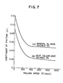
- the higher the rolling speed becomes the lower the coefficient of friction becomes. This relationship is shown in Fig.
- curves A and B represent rolling operations using as a roll coolant a mineral oil base soluble oil and a beef tallow base soluble oil, respectively, which are usually used when a steel strip is subjected to cold rolling.
- the curves A and B indicate that coefficient of friction p is greatly changed in compliance with the rolling speed.
- the idea of using a roll coolant of high coefficient of friction to avoid the occurrence of a slip might come to mind. However, when such idea is put into practice, galling would occur between the rolls and the strip and it would be impossible to continue the rolling operation. To obviate this problem, the invention imparts rolling energy to a strip in the form of a difference in tension between one rolling point and another. In the system of the prior art shown in Fig.
- the strip to be rolled wound on the rolling rolls has rolling energy imparted thereto by the frictional force exerted by the rolling rolls.
- a slip occurs in this system, there is a care of causing the roll marks.
- the invention aims at imparting a difference in tension to the strip without relying on the rolling rolls as has been the case with the prior art. The end is attained by increasing tension at the delivery end of one rolling point and decreasing the tension at the entering end of the next following rolling point. Operation of the system of the invention with a marked increase in rolling reduction and a greatly improved efficiency of multiple pass rolling will now be described.
- Fig. 8 shows the balancing of forces.
- a force urging the strip to move rearwardly is obtained by T 2 ' - T 3 + 2 x P sin because there is no acceleration.
- the force with which the rolling rolls urge the strip to move forwardly is expressed by F shown by equation (1).
- F is 2 ⁇ P, and 6 is small in value.
- means is provided for varying the tension applied to the strip so as to effect a rolling reduction of large magnitude at each of the first, second and third rolling points as described hereinabove and perform three pass rolling with a high degree of efficiency at a single stand rolling mill by increasing the delivery side tension T 2 at the first rolling point and decreasing the entering side tension T 2 ' at the second rolling point.
- the tensions at the delivery end and the entering end of the bridle roller 7 are distinct from each other as designated by T 2 and T 2 '.
- T 2 and T 2 ' are compared with set values 21 to see whether they are optimum values, and a command signal is issued based on the result of comparison and fed into the drive 15 for the bridle roller 7, to positively control the tension of the strip 10.
- the speed of the strip 10 can be sensed by speed sensors 17 and 18 attached to the bridle rollers 7 and 8 respectively.
- the ability to apply tension to the strip can be increased by increasing the coefficient of friction of the surfaces of the bridle rollers and increasing the angle at which the strip is wound on each roller.
- An increase in the coefficient of friction of the surfaces of the bridle rollers can be achieved by coarsening the surfaces of the bridle rollers by applying a shot blast thereto or by applying to the surfaces of the bridle rollers a material tending to increase the coefficient of friction.
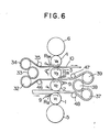
- An increase in the strip winding angle may be achieved by using a plurality of sets of bridle rollers 37, 38 and 39 and 32, 33 and 34 as shown in Fig. 6 which shows another embodiment of the invention.
- the numerals 46, 47 and 48 designate guide rollers. However, these are not restrictive and tension gauges may be used in place of the guide rollers. Also, a drive may be connected to each of the bridle rollers 32 - 39.
- the one rolling roll of the plurality of rolling rolls cooperating with other rolls to roll a strip simultaneously at a plurality of rolling points is two in number.
- the invention is not limited to this specific number of the one rolling roll and the number of the one rolling roll may be one as shown in Fig. 10 which shows still another embodiment in which rolling is performed simultaneously at two rolling points, in this case, the number of the rolling rolls performing rolling of the strip 10 includes three working rolls 1, 2 and 3.
- tension difference applying means is one in number which creates a difference in tension in a portion of the strop 10 disposed between a rolling point at which rolling is effected by the working rolls 1 and 2 of different circumferential speeds and the other rolling point at which rolling is effected by the working rolls 2 and 3 of different circumferential speed.
- the construction of the different circumferential speed continuous rolling mill shown in Fig. 10 having tension difference applying means attached to the bridle roller 7 is basically the same as the construction of the different circumferential speed continuous rolling mill shown in Fig. 5, so that the description of the construction shown in Fig. 10 will be omitted.
- the rolling points at which rolling is simultaneously effected by the one roll in cooperation with other rolling rolls are two in number.
- this is not restrictive and the invention may bave application in a continuous rolling system in which rolling is performed simultaneously at three or four rolling points by the one rolling roll cooperating with other rolling rolls.
- Fig. 11 shows a further embodiment in which an internal working roll 40 is surrounded by external working rolls 50a, 50b and 50c supported by respective backing-up rolls 60 and rotating at circumferential speeds v 2 , v3 and v 4 respectively which are distinct from the circumferential speed v I of the internal working roll 40, so that the strip 10 can be rolled simultaneously at three rolling points.
- a bridle roller 70a is located in a path of travel of the strip 10 between a first rolling point between the internal working roll 40 and first external working roll 50a and a second rolling point between the internal working roll 40 and second external working roll 50b.
- the bridle roll 70a is provided with a drive 15 and supplies rolling energy to the strip 10.
- Another bridle roll 70 provided with a drive 16 is located in a path of travel of the strip 10 between the second rolling point and a third rolling point between the internal working roll 40 and third external working roll 50c to supply rolling energy to the strip 10.
- the numerals 80 and 9 designate guide rollers for the strip 10 and fluid spray means for effecting cooling and lubrication of the strip 10, respectively.
- rolling energy of sufficiently high magnitude can be supplied to the strip between the rolling passes to enable the continuous rolling with a high degree of efficiency in the same way other embodiments of the invention.
- a different circumferential speed continuous rolling mill capable of supplying rolling energy to the strip between the rolling passes from means other than the rolling rolls, to thereby enable continuous rolling to be effected with a high degree of efficiency.
Landscapes
- Engineering & Computer Science (AREA)
- Mechanical Engineering (AREA)
- Metal Rolling (AREA)
- Control Of Metal Rolling (AREA)
Applications Claiming Priority (2)
| Application Number | Priority Date | Filing Date | Title |
|---|---|---|---|
| JP57218978A JPS59107703A (ja) | 1982-12-13 | 1982-12-13 | 異周速連続圧延機 |
| JP218978/82 | 1982-12-13 |
Publications (2)
| Publication Number | Publication Date |
|---|---|
| EP0111865A2 true EP0111865A2 (fr) | 1984-06-27 |
| EP0111865A3 EP0111865A3 (fr) | 1984-10-10 |
Family
ID=16728342
Family Applications (1)
| Application Number | Title | Priority Date | Filing Date |
|---|---|---|---|
| EP83112482A Withdrawn EP0111865A3 (fr) | 1982-12-13 | 1983-12-12 | Laminoir à vitesses circonférentielles différentes |
Country Status (2)
| Country | Link |
|---|---|
| EP (1) | EP0111865A3 (fr) |
| JP (1) | JPS59107703A (fr) |
Cited By (1)
| Publication number | Priority date | Publication date | Assignee | Title |
|---|---|---|---|---|
| CN115770788A (zh) * | 2022-12-29 | 2023-03-10 | 佛山市建创业精密钢带有限公司 | 一种多道轧制钢带设备及方法 |
Family Cites Families (3)
| Publication number | Priority date | Publication date | Assignee | Title |
|---|---|---|---|---|
| FR2049640A5 (fr) * | 1969-06-16 | 1971-03-26 | Ch Politekhnic | |
| SU687668A1 (ru) * | 1976-11-17 | 1981-06-30 | Челябинский Политехнический Институтим.Ленинского Комсомола | Способ неприрывной прокатки и стандл ЕгО ОСущЕСТВлЕНи |
| US4244203A (en) * | 1979-03-29 | 1981-01-13 | Olin Corporation | Cooperative rolling process and apparatus |
-
1982
- 1982-12-13 JP JP57218978A patent/JPS59107703A/ja active Granted
-
1983
- 1983-12-12 EP EP83112482A patent/EP0111865A3/fr not_active Withdrawn
Cited By (1)
| Publication number | Priority date | Publication date | Assignee | Title |
|---|---|---|---|---|
| CN115770788A (zh) * | 2022-12-29 | 2023-03-10 | 佛山市建创业精密钢带有限公司 | 一种多道轧制钢带设备及方法 |
Also Published As
| Publication number | Publication date |
|---|---|
| JPH0510161B2 (fr) | 1993-02-09 |
| EP0111865A3 (fr) | 1984-10-10 |
| JPS59107703A (ja) | 1984-06-22 |
Similar Documents
| Publication | Publication Date | Title |
|---|---|---|
| EP0615793B2 (fr) | Procédé de laminage à chaud | |
| RU2057601C1 (ru) | Способ горячей прокатки стальной полосы и установка для его осуществления | |
| US5448901A (en) | Method for controlling axial shifting of rolls | |
| EP0088443B1 (fr) | Laminoir | |
| US6076388A (en) | Rolling mill, hot rolling system, rolling method and rolling mill revamping method | |
| CA1147990A (fr) | Laminoir a rouleau profileur de configuration variable | |
| EP0745440B1 (fr) | Train à feuillards à chaud | |
| US3459019A (en) | Method of and apparatus for rolling flat strip | |
| JP3283823B2 (ja) | 板材圧延機 | |
| KR980008371A (ko) | 압연기용 구동 장치, 압연기 및 압연 방법 | |
| KR100226805B1 (ko) | 금속띠 부재의 냉간 압연방법 | |
| JPH11513937A (ja) | 形状計測装置を備えた熱間ストリップ可逆圧延機 | |
| EP0896840B1 (fr) | Laminoir, et procede et equipement de laminage | |
| EP0111865A2 (fr) | Laminoir à vitesses circonférentielles différentes | |
| US6463777B1 (en) | Method for the continuous production of a metal strip | |
| EP0142577A1 (fr) | Dispositif d'entraînement de décintreuses à galets | |
| JPH0217244B2 (fr) | ||
| JPS636282B2 (fr) | ||
| CN106269913A (zh) | 工作辊横移轧机防止带钢跑偏的方法 | |
| EP0110556A2 (fr) | Procédé de laminage pour train de laminoir à chaud duo et produit à feuillard étroit | |
| JPH0318411A (ja) | 形状制御性にすぐれた冷間圧延方法 | |
| EP0107970A1 (fr) | Conception de cylindre à centrage automatique pour laminoir à chaud | |
| JPS5916605A (ja) | 多段クラスタ−圧延機および板材圧延法 | |
| US2075273A (en) | Method of rolling metals | |
| JP3249313B2 (ja) | 圧延機及び圧延機の圧延方法並びに圧延機の使用方法 |
Legal Events
| Date | Code | Title | Description |
|---|---|---|---|
| PUAI | Public reference made under article 153(3) epc to a published international application that has entered the european phase |
Free format text: ORIGINAL CODE: 0009012 |
|
| AK | Designated contracting states |
Designated state(s): DE FR GB IT |
|
| PUAL | Search report despatched |
Free format text: ORIGINAL CODE: 0009013 |
|
| AK | Designated contracting states |
Designated state(s): DE FR GB IT |
|
| 17P | Request for examination filed |
Effective date: 19841011 |
|
| STAA | Information on the status of an ep patent application or granted ep patent |
Free format text: STATUS: THE APPLICATION HAS BEEN WITHDRAWN |
|
| 18W | Application withdrawn |
Withdrawal date: 19860117 |
|
| RIN1 | Information on inventor provided before grant (corrected) |
Inventor name: KAJIWARA, TOSHIYUKI |