EP0142577A1 - Dispositif d'entraînement de décintreuses à galets - Google Patents
Dispositif d'entraînement de décintreuses à galets Download PDFInfo
- Publication number
- EP0142577A1 EP0142577A1 EP83111678A EP83111678A EP0142577A1 EP 0142577 A1 EP0142577 A1 EP 0142577A1 EP 83111678 A EP83111678 A EP 83111678A EP 83111678 A EP83111678 A EP 83111678A EP 0142577 A1 EP0142577 A1 EP 0142577A1
- Authority
- EP
- European Patent Office
- Prior art keywords
- torque
- driving
- rolls
- roller leveler
- shafts
- Prior art date
- Legal status (The legal status is an assumption and is not a legal conclusion. Google has not performed a legal analysis and makes no representation as to the accuracy of the status listed.)
- Withdrawn
Links
Images


Classifications
-
- B—PERFORMING OPERATIONS; TRANSPORTING
- B21—MECHANICAL METAL-WORKING WITHOUT ESSENTIALLY REMOVING MATERIAL; PUNCHING METAL
- B21D—WORKING OR PROCESSING OF SHEET METAL OR METAL TUBES, RODS OR PROFILES WITHOUT ESSENTIALLY REMOVING MATERIAL; PUNCHING METAL
- B21D1/00—Straightening, restoring form or removing local distortions of sheet metal or specific articles made therefrom; Stretching sheet metal combined with rolling
- B21D1/02—Straightening, restoring form or removing local distortions of sheet metal or specific articles made therefrom; Stretching sheet metal combined with rolling by rollers
Definitions
- This invention relates to an apparatus for driving a roller leveler that levels such steel plates, especially heavier-gage ones than those which develop excess unbending reactive force and torque during leveling.
- the hot roller leveler for use in the continuous in-line quality control cooling process must have:
- Fig. 1 shows an example of a roller leveler driving apparatus of the conventional type which essentially comprises a drive motor 1,' speed reducer 2, distributor 3 and spindle (not shown).
- the rotation produced by the drive motor 1 is reduced by the reduction gears 4 in the speed reducer 2 and then transmitted to five intermediate shafts 6 via large distribution gears 5.
- the rotation is further transmitted to thirteen driving shafts 8 via small distribution gears 7 in the distributor 3.
- the power from the motor 1 is transmitted to each pair of top and bottom leveling rolls (not shown) through a spindle (not shown) coupled to each of the driving shafts 8.
- the object of this invention is to provide an apparatus for driving a roller leveler that permits steel plates to be leveled safely and smoothly, avoiding the development of excess torque that might lead to the fracture of the drive unit.
- a torque-limiting coupling is attached to all, or all but one, output shafts to which the motion of a single driving unit is transmitted in an apparatus for driving a roller leveler which comprises a plurality of bottom straightening rolls that are disposed at intervals below the pass line of the piece and top straightening rolls that are disposed, zigzagged with respect to the bottom rolls, above the same pass line.
- the apparatus sends the piece forward while flattening by driving the bottom and top rolls simultaneously.
- the torque control coupling absorbs the energy generated by it, so no torque greater than the predetermined level is transmitted to the driving unit. Also, conversely, even if the output of the driving unit works concentratedly on a single intermediate or distribution shaft, the torque transmitted is kept to the predetermined level.
- Figs. 2 and 3 briefly show the mechanism by which the friction torque is produced.
- the plate 11 is bent by the i-th leveling roll 10 arid gets curved to a radius R i at a point of contact with the roll. Since the center of curvature O can be an instantaneous one, the relationship between the velocity V . of the neutral plane in the direction of plate thickness and the peripheral velocity V o of the roll can be expressed as follows, if the peripheral velocity V is constant and, in addition, equal to the surface velocity of the plate or, in other words, if no slippage occurs between the surface of the plate and the roll:
- Equation (1) or the aforesaid condi-. tions do not hold. Then, slippage occurs between the plate and rolls in order to reduce the roll-to-roll speed difference as the neutral plane velocity V i of the plate 11 should essentially be constant.
- the re- a sult is the creation of/frictional force, as shown in Fig. 3.
- P a , P b and P c designate the reactive forces that are developed against the leveling action on the rolls 10a, 10b and 10c, ⁇ the coefficient of kinetic friction, fa and f c the frictional forces. If the roll radius is r, then the frictional torques T a and T c can be expressed as follows:
- Equations (2) and (3) show that the friction torque is proportional to the reactive force against the leveling action.
- the reactive force varies from roll to roll as it increases with an increase in the amount of pressing.
- equation (1) therefore, a group of rolls that provide heavier pressing cause the plate to move forward at a higher speed, thus producing a greater friction torque. Consequently, such a group of rolls tend to rotate other group or groups of rolls that provide lighter pressing (and, therefore, impart lower travelling speed and develop smaller reactive force). Therefore, a/ positive friction torque develops on the group of rolls providing heavier pressing whereby the plate is caused to move forward through the rolls while a being flattened, whereas/negative friction torque develops on the group of rolls providing lighter pressing whereby the rolls are rotated by the motion of the plate.
- the driving apparatus of the roller leveler is designed to drive groups of rolls through a mechanical coupling, positive and negative torques are exchanged among the individual groups. Being much greater than the flattening torque that is derived from an ordinary theoretical equation, the friction torque often causes the fracture of a spindle and other troubles. Even if the driving force for each roll is varied in advance depending on the roll-diameter, the development of the friction torque cannot be avoided since it arises if the amount of pressing and/or roll diameter varies, even slightly, from roll to roll. Providing a separate driving apparatus to each roll is also virtually meaningless because the friction torque develops in each unit. The foregoing may be summarized as follows:
- a friction torque can be caused also by other phenomena than those described above, such as:
- This invention perfectly eliminates the likelihood of the roller leveler driving apparatus of getting damaged or broken by the excess friction torque deve- lopped between the plate and leveler rolls and permits the plate to be straightened safely and smoothly.
- a roller leveler driving apparatus embodying the principle of this invention will be described in the following by reference to Fig. 4.
- the arrangement and structure of a motor 1, speed reducer 2 and distributor 3 are identical to those shown in Fig. 1.
- the driving method is of the mechanical coupling type whereby the rotation from the motor is transmitted to thirteen distribution shafts 8a through 8m by way of five intermediate shafts 6a through 6e.
- Couplings 12 and a torque-limiting coupling 13 are attached to the distribution shafts 8a through 8m on the output side of the distributor 3.
- the torque-limiting coupling is a generic name given to couplings such as hydraulic or friction clutch coupl- ingsthat keep substantially constant the torque that is transmitted from the driving side to the driven side, or in the opposite direction,
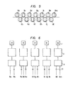
- Fig. 5 is a cross section
- the function of the torque-limiting coupling is to limit the amount of torque working on the individual distribution shafts 8a through 8m. Even if any excess friction torque is developed as a result of a slippage between the plate and roll, no torque greater than the predetermined one is transmitted to the driving unit. Even if, conversely, the power of the motor 1 works concentratedly on only one intermediate or distribution shaft, no torque greater than the predetermined one is allowed to develop. While the positive and negative friction torques are being eliminated, such an amount of torque as is necessary for flattening is transmitted through the torque-limiting coupling to ensure a smooth leveling operation.
- the roller leveler With all excess torque reduced to the predetermined level, the roller leveler is now able to perform its leveling function stably freed from the excess- torque-induced breakage of its driving unit or other troubles.
- the torque-limiting coupling may be equipped with a mechanism to vary, either stepwise or continuously, the level of the torque transmitted therethrough.
- one torque-limiting coupling 13 is attached to all distribution shafts 8a through 8m. Or otherwise, as shown in Fig. 6, an independent motor may be provided to each roll, with a torque-limiting coupling 13 attached to all or all but one distribution shafts in each driving unit.
- the driving apparatus according to this invention is suited for use with roller levelers that flatten steel plates and other plate-formed products, especially those products which develop excess reactive force and torque during leveling.
- the driving apparatus of this invention can be used not only with hot roller levelers but also with all kinds of roller levelers.
Landscapes
- Engineering & Computer Science (AREA)
- Mechanical Engineering (AREA)
- Straightening Metal Sheet-Like Bodies (AREA)
Priority Applications (1)
| Application Number | Priority Date | Filing Date | Title |
|---|---|---|---|
| EP83111678A EP0142577A1 (fr) | 1983-11-22 | 1983-11-22 | Dispositif d'entraînement de décintreuses à galets |
Applications Claiming Priority (1)
| Application Number | Priority Date | Filing Date | Title |
|---|---|---|---|
| EP83111678A EP0142577A1 (fr) | 1983-11-22 | 1983-11-22 | Dispositif d'entraînement de décintreuses à galets |
Publications (1)
| Publication Number | Publication Date |
|---|---|
| EP0142577A1 true EP0142577A1 (fr) | 1985-05-29 |
Family
ID=8190823
Family Applications (1)
| Application Number | Title | Priority Date | Filing Date |
|---|---|---|---|
| EP83111678A Withdrawn EP0142577A1 (fr) | 1983-11-22 | 1983-11-22 | Dispositif d'entraînement de décintreuses à galets |
Country Status (1)
| Country | Link |
|---|---|
| EP (1) | EP0142577A1 (fr) |
Cited By (9)
| Publication number | Priority date | Publication date | Assignee | Title |
|---|---|---|---|---|
| EP1584384A1 (fr) * | 2004-04-07 | 2005-10-12 | Sundwig GmbH | Machine à dresser avec cassette interchangeable |
| EP2058059A1 (fr) * | 2007-11-07 | 2009-05-13 | The Bradbury Company, Inc. | Procédés et appareil pour la commande de machines de conditionnement de matériaux |
| EP2116315B2 (fr) † | 2008-05-08 | 2013-03-13 | Arku Maschinenbau Gmbh | Machine de dressage à rouleaux avec système de changement de cassette |
| ITMI20130229A1 (it) * | 2013-02-19 | 2014-08-20 | I | Spianatrice a rulli per lamiere e procedimento per spianare con essa una lamiera |
| US9050638B2 (en) | 2010-10-06 | 2015-06-09 | The Bradbury Company, Inc. | Apparatus and methods to increase the efficiency of roll-forming and leveling systems |
| CN110762168A (zh) * | 2018-07-27 | 2020-02-07 | 江苏泰隆减速机股份有限公司 | 一种矫直机用减速机 |
| CN111558629A (zh) * | 2020-04-22 | 2020-08-21 | 中国重型机械研究院股份公司 | 一种辊式矫直机矫直辊独立传动组件和传动方法 |
| CN118357309A (zh) * | 2024-06-19 | 2024-07-19 | 中南大学 | 一种高筋壁板局部矫直装置及矫直方法 |
| CN120991037A (zh) * | 2025-10-16 | 2025-11-21 | 南京杰亚挤出装备有限公司 | 卧式三转子脱挥混合机用传动箱 |
Citations (4)
| Publication number | Priority date | Publication date | Assignee | Title |
|---|---|---|---|---|
| FR1522634A (fr) * | 1967-03-28 | 1968-04-26 | Wtz Feikeramischen Ind | Commande pour laminoirs et décintreuses à galets |
| FR1599475A (fr) * | 1968-12-27 | 1970-07-15 | ||
| GB1230860A (fr) * | 1968-12-23 | 1971-05-05 | ||
| DE2103892A1 (en) * | 1971-01-28 | 1972-08-24 | Schloemann AG, 4000 Düsseldorf | Sheet metal straightening - partic cold plate by a reverse bending method |
-
1983
- 1983-11-22 EP EP83111678A patent/EP0142577A1/fr not_active Withdrawn
Patent Citations (4)
| Publication number | Priority date | Publication date | Assignee | Title |
|---|---|---|---|---|
| FR1522634A (fr) * | 1967-03-28 | 1968-04-26 | Wtz Feikeramischen Ind | Commande pour laminoirs et décintreuses à galets |
| GB1230860A (fr) * | 1968-12-23 | 1971-05-05 | ||
| FR1599475A (fr) * | 1968-12-27 | 1970-07-15 | ||
| DE2103892A1 (en) * | 1971-01-28 | 1972-08-24 | Schloemann AG, 4000 Düsseldorf | Sheet metal straightening - partic cold plate by a reverse bending method |
Cited By (16)
| Publication number | Priority date | Publication date | Assignee | Title |
|---|---|---|---|---|
| EP1584384A1 (fr) * | 2004-04-07 | 2005-10-12 | Sundwig GmbH | Machine à dresser avec cassette interchangeable |
| EP2058059A1 (fr) * | 2007-11-07 | 2009-05-13 | The Bradbury Company, Inc. | Procédés et appareil pour la commande de machines de conditionnement de matériaux |
| US10537923B2 (en) | 2007-11-07 | 2020-01-21 | The Bradbury Company, Inc. | Methods to drive material conditioning machines |
| US8893537B2 (en) | 2007-11-07 | 2014-11-25 | The Bradbury Company, Inc. | Methods and apparatus to drive material conditioning machines |
| EP2116315B2 (fr) † | 2008-05-08 | 2013-03-13 | Arku Maschinenbau Gmbh | Machine de dressage à rouleaux avec système de changement de cassette |
| US11045850B2 (en) | 2010-10-06 | 2021-06-29 | The Bradbury Company, Inc. | Apparatus and methods to increase the efficiency of roll-forming and leveling systems |
| US9050638B2 (en) | 2010-10-06 | 2015-06-09 | The Bradbury Company, Inc. | Apparatus and methods to increase the efficiency of roll-forming and leveling systems |
| US10252306B2 (en) | 2010-10-06 | 2019-04-09 | The Bradbury Company, Inc. | Apparatus and methods to increase the efficiency of roll-forming and leveling systems |
| EP2958688B1 (fr) | 2013-02-19 | 2018-04-04 | F.I.M.I. - Fabbrica Impianti Machine Industriali - S.p.A. | Dispositif de mise à niveau de rouleau pour tôles métalliques et procédé de mise à niveau d'une tôle métallique avec celui-ci |
| US9901967B2 (en) | 2013-02-19 | 2018-02-27 | F.I.M.I.—Fabbrica Impianti Macchine Industriali—S.P.A. | Roll leveller for metal sheets and a process for levelling a metal sheet with it |
| WO2014128614A1 (fr) * | 2013-02-19 | 2014-08-28 | F.I.M.I. - Fabbrica Impianti Macchine Industriali - S.P.A. | Dispositif de mise à niveau de rouleau pour tôles métalliques et procédé de mise à niveau d'une tôle métallique avec celui-ci |
| ITMI20130229A1 (it) * | 2013-02-19 | 2014-08-20 | I | Spianatrice a rulli per lamiere e procedimento per spianare con essa una lamiera |
| CN110762168A (zh) * | 2018-07-27 | 2020-02-07 | 江苏泰隆减速机股份有限公司 | 一种矫直机用减速机 |
| CN111558629A (zh) * | 2020-04-22 | 2020-08-21 | 中国重型机械研究院股份公司 | 一种辊式矫直机矫直辊独立传动组件和传动方法 |
| CN118357309A (zh) * | 2024-06-19 | 2024-07-19 | 中南大学 | 一种高筋壁板局部矫直装置及矫直方法 |
| CN120991037A (zh) * | 2025-10-16 | 2025-11-21 | 南京杰亚挤出装备有限公司 | 卧式三转子脱挥混合机用传动箱 |
Similar Documents
| Publication | Publication Date | Title |
|---|---|---|
| US4385511A (en) | Method of rolling metal articles | |
| US11845117B2 (en) | Asynchronous rolling mill with a super large diameter ratio and sheet rolling method | |
| US4365496A (en) | Rolling process | |
| US3823593A (en) | Method of rolling metal sheet articles between the driven rolls of the roll mill | |
| US4194382A (en) | Rolling mill | |
| EP0188113B2 (fr) | Procédé de contrÔle de section de feuilles de tÔle et laminoir | |
| US5174144A (en) | 4-high rolling mill | |
| EP0142577A1 (fr) | Dispositif d'entraînement de décintreuses à galets | |
| US5448901A (en) | Method for controlling axial shifting of rolls | |
| Pan et al. | An experimental study of the effect of roll-speed mismatch on the rolling load during the cold rolling of thin strip | |
| EP0088443B1 (fr) | Laminoir | |
| US6216517B1 (en) | Precision-rolling process | |
| US4074557A (en) | Metal extrusion process with high reduction | |
| KR960013872B1 (ko) | 금속판표면의 광택부여방법 및 금속재의 냉간압연방법 | |
| JPH11347607A (ja) | 板材圧延機 | |
| EP0745440A1 (fr) | Dispositif auxiliaire pour enfiler, laminoir et installation de laminage | |
| JPH0217244B2 (fr) | ||
| JP7620734B2 (ja) | 作業ロールバランス力設定方法、および圧延機の運転方法、圧延機の運転切り替え方法、並びに圧延機 | |
| WO2020235199A1 (fr) | Laminoir, procédé de laminage et procédé de fonctionnement pour rouleau de travail | |
| JPS6147612B2 (fr) | ||
| Omori et al. | Analysis of rolling load generated by pair crossed rolling mill | |
| SU1555004A1 (ru) | Способ прокатки полос и лент | |
| EP0111865A2 (fr) | Laminoir à vitesses circonférentielles différentes | |
| JPH057081B2 (fr) | ||
| JPS5910843B2 (ja) | 異速圧延方法および異速圧延機 |
Legal Events
| Date | Code | Title | Description |
|---|---|---|---|
| PUAI | Public reference made under article 153(3) epc to a published international application that has entered the european phase |
Free format text: ORIGINAL CODE: 0009012 |
|
| AK | Designated contracting states |
Designated state(s): DE IT |
|
| 18D | Application deemed to be withdrawn |
Effective date: 19860130 |
|
| RIN1 | Information on inventor provided before grant (corrected) |
Inventor name: MIYAKAWA, HIROSHIC/O NIPPON STEEL CORPORATION Inventor name: TORIYAMA, YOSHIMIC/O NIPPON STEEL CORPORATION |