EP0112089A1 - Système d'admission d'un mélange air-carburant pour moteur à combustion interne à plusieurs cylindres - Google Patents
Système d'admission d'un mélange air-carburant pour moteur à combustion interne à plusieurs cylindres Download PDFInfo
- Publication number
- EP0112089A1 EP0112089A1 EP83307277A EP83307277A EP0112089A1 EP 0112089 A1 EP0112089 A1 EP 0112089A1 EP 83307277 A EP83307277 A EP 83307277A EP 83307277 A EP83307277 A EP 83307277A EP 0112089 A1 EP0112089 A1 EP 0112089A1
- Authority
- EP
- European Patent Office
- Prior art keywords
- engine
- fuel
- valves
- valve
- gaseous fuel
- Prior art date
- Legal status (The legal status is an assumption and is not a legal conclusion. Google has not performed a legal analysis and makes no representation as to the accuracy of the status listed.)
- Withdrawn
Links
- 239000000446 fuel Substances 0.000 title claims abstract description 68
- 230000006698 induction Effects 0.000 title claims abstract description 38
- 238000002485 combustion reaction Methods 0.000 title claims description 6
- 238000002347 injection Methods 0.000 claims abstract description 62
- 239000007924 injection Substances 0.000 claims abstract description 62
- 239000011159 matrix material Substances 0.000 claims abstract description 10
- 238000010304 firing Methods 0.000 claims abstract description 9
- 238000004891 communication Methods 0.000 claims description 12
- 239000000203 mixture Substances 0.000 claims description 6
- 238000010348 incorporation Methods 0.000 claims 1
- 238000010438 heat treatment Methods 0.000 abstract description 3
- 239000003915 liquefied petroleum gas Substances 0.000 description 18
- 238000004804 winding Methods 0.000 description 6
- 230000009977 dual effect Effects 0.000 description 4
- 230000001276 controlling effect Effects 0.000 description 3
- 230000001105 regulatory effect Effects 0.000 description 3
- 230000001360 synchronised effect Effects 0.000 description 3
- 238000010276 construction Methods 0.000 description 2
- 238000010586 diagram Methods 0.000 description 2
- 239000007789 gas Substances 0.000 description 2
- 230000005355 Hall effect Effects 0.000 description 1
- 238000006243 chemical reaction Methods 0.000 description 1
- 239000002826 coolant Substances 0.000 description 1
- 239000000498 cooling water Substances 0.000 description 1
- 230000003111 delayed effect Effects 0.000 description 1
- 230000006870 function Effects 0.000 description 1
- 239000007788 liquid Substances 0.000 description 1
- 238000000034 method Methods 0.000 description 1
- 238000002156 mixing Methods 0.000 description 1
- 238000012986 modification Methods 0.000 description 1
- 230000004048 modification Effects 0.000 description 1
- 230000000630 rising effect Effects 0.000 description 1
- 230000035945 sensitivity Effects 0.000 description 1
- 238000011144 upstream manufacturing Methods 0.000 description 1
Images




Classifications
-
- F—MECHANICAL ENGINEERING; LIGHTING; HEATING; WEAPONS; BLASTING
- F02—COMBUSTION ENGINES; HOT-GAS OR COMBUSTION-PRODUCT ENGINE PLANTS
- F02D—CONTROLLING COMBUSTION ENGINES
- F02D41/00—Electrical control of supply of combustible mixture or its constituents
- F02D41/30—Controlling fuel injection
- F02D41/32—Controlling fuel injection of the low pressure type
- F02D41/36—Controlling fuel injection of the low pressure type with means for controlling distribution
- F02D41/365—Controlling fuel injection of the low pressure type with means for controlling distribution with means for controlling timing and distribution
-
- F—MECHANICAL ENGINEERING; LIGHTING; HEATING; WEAPONS; BLASTING
- F02—COMBUSTION ENGINES; HOT-GAS OR COMBUSTION-PRODUCT ENGINE PLANTS
- F02D—CONTROLLING COMBUSTION ENGINES
- F02D19/00—Controlling engines characterised by their use of non-liquid fuels, pluralities of fuels, or non-fuel substances added to the combustible mixtures
- F02D19/02—Controlling engines characterised by their use of non-liquid fuels, pluralities of fuels, or non-fuel substances added to the combustible mixtures peculiar to engines working with gaseous fuels
- F02D19/021—Control of components of the fuel supply system
- F02D19/023—Control of components of the fuel supply system to adjust the fuel mass or volume flow
- F02D19/024—Control of components of the fuel supply system to adjust the fuel mass or volume flow by controlling fuel injectors
-
- F—MECHANICAL ENGINEERING; LIGHTING; HEATING; WEAPONS; BLASTING
- F02—COMBUSTION ENGINES; HOT-GAS OR COMBUSTION-PRODUCT ENGINE PLANTS
- F02D—CONTROLLING COMBUSTION ENGINES
- F02D41/00—Electrical control of supply of combustible mixture or its constituents
- F02D41/0025—Controlling engines characterised by use of non-liquid fuels, pluralities of fuels, or non-fuel substances added to the combustible mixtures
- F02D41/0027—Controlling engines characterised by use of non-liquid fuels, pluralities of fuels, or non-fuel substances added to the combustible mixtures the fuel being gaseous
-
- F—MECHANICAL ENGINEERING; LIGHTING; HEATING; WEAPONS; BLASTING
- F02—COMBUSTION ENGINES; HOT-GAS OR COMBUSTION-PRODUCT ENGINE PLANTS
- F02D—CONTROLLING COMBUSTION ENGINES
- F02D41/00—Electrical control of supply of combustible mixture or its constituents
- F02D41/02—Circuit arrangements for generating control signals
- F02D41/04—Introducing corrections for particular operating conditions
- F02D41/08—Introducing corrections for particular operating conditions for idling
-
- F—MECHANICAL ENGINEERING; LIGHTING; HEATING; WEAPONS; BLASTING
- F02—COMBUSTION ENGINES; HOT-GAS OR COMBUSTION-PRODUCT ENGINE PLANTS
- F02D—CONTROLLING COMBUSTION ENGINES
- F02D41/00—Electrical control of supply of combustible mixture or its constituents
- F02D41/02—Circuit arrangements for generating control signals
- F02D41/04—Introducing corrections for particular operating conditions
- F02D41/10—Introducing corrections for particular operating conditions for acceleration
-
- F—MECHANICAL ENGINEERING; LIGHTING; HEATING; WEAPONS; BLASTING
- F02—COMBUSTION ENGINES; HOT-GAS OR COMBUSTION-PRODUCT ENGINE PLANTS
- F02M—SUPPLYING COMBUSTION ENGINES IN GENERAL WITH COMBUSTIBLE MIXTURES OR CONSTITUENTS THEREOF
- F02M21/00—Apparatus for supplying engines with non-liquid fuels, e.g. gaseous fuels stored in liquid form
- F02M21/02—Apparatus for supplying engines with non-liquid fuels, e.g. gaseous fuels stored in liquid form for gaseous fuels
- F02M21/0203—Apparatus for supplying engines with non-liquid fuels, e.g. gaseous fuels stored in liquid form for gaseous fuels characterised by the type of gaseous fuel
- F02M21/0209—Hydrocarbon fuels, e.g. methane or acetylene
- F02M21/0212—Hydrocarbon fuels, e.g. methane or acetylene comprising at least 3 C-Atoms, e.g. liquefied petroleum gas [LPG], propane or butane
-
- F—MECHANICAL ENGINEERING; LIGHTING; HEATING; WEAPONS; BLASTING
- F02—COMBUSTION ENGINES; HOT-GAS OR COMBUSTION-PRODUCT ENGINE PLANTS
- F02M—SUPPLYING COMBUSTION ENGINES IN GENERAL WITH COMBUSTIBLE MIXTURES OR CONSTITUENTS THEREOF
- F02M21/00—Apparatus for supplying engines with non-liquid fuels, e.g. gaseous fuels stored in liquid form
- F02M21/02—Apparatus for supplying engines with non-liquid fuels, e.g. gaseous fuels stored in liquid form for gaseous fuels
- F02M21/0218—Details on the gaseous fuel supply system, e.g. tanks, valves, pipes, pumps, rails, injectors or mixers
- F02M21/0248—Injectors
- F02M21/0251—Details of actuators therefor
- F02M21/0254—Electric actuators, e.g. solenoid or piezoelectric
-
- F—MECHANICAL ENGINEERING; LIGHTING; HEATING; WEAPONS; BLASTING
- F02—COMBUSTION ENGINES; HOT-GAS OR COMBUSTION-PRODUCT ENGINE PLANTS
- F02M—SUPPLYING COMBUSTION ENGINES IN GENERAL WITH COMBUSTIBLE MIXTURES OR CONSTITUENTS THEREOF
- F02M21/00—Apparatus for supplying engines with non-liquid fuels, e.g. gaseous fuels stored in liquid form
- F02M21/02—Apparatus for supplying engines with non-liquid fuels, e.g. gaseous fuels stored in liquid form for gaseous fuels
- F02M21/0218—Details on the gaseous fuel supply system, e.g. tanks, valves, pipes, pumps, rails, injectors or mixers
- F02M21/0248—Injectors
- F02M21/0257—Details of the valve closing elements, e.g. valve seats, stems or arrangement of flow passages
- F02M21/026—Lift valves, i.e. stem operated valves
- F02M21/0263—Inwardly opening single or multi nozzle valves, e.g. needle valves
- F02M21/0266—Hollow stem valves; Piston valves; Stems having a spherical tip
-
- F—MECHANICAL ENGINEERING; LIGHTING; HEATING; WEAPONS; BLASTING
- F02—COMBUSTION ENGINES; HOT-GAS OR COMBUSTION-PRODUCT ENGINE PLANTS
- F02M—SUPPLYING COMBUSTION ENGINES IN GENERAL WITH COMBUSTIBLE MIXTURES OR CONSTITUENTS THEREOF
- F02M21/00—Apparatus for supplying engines with non-liquid fuels, e.g. gaseous fuels stored in liquid form
- F02M21/02—Apparatus for supplying engines with non-liquid fuels, e.g. gaseous fuels stored in liquid form for gaseous fuels
- F02M21/0218—Details on the gaseous fuel supply system, e.g. tanks, valves, pipes, pumps, rails, injectors or mixers
- F02M21/0248—Injectors
- F02M21/0278—Port fuel injectors for single or multipoint injection into the air intake system
-
- F—MECHANICAL ENGINEERING; LIGHTING; HEATING; WEAPONS; BLASTING
- F02—COMBUSTION ENGINES; HOT-GAS OR COMBUSTION-PRODUCT ENGINE PLANTS
- F02M—SUPPLYING COMBUSTION ENGINES IN GENERAL WITH COMBUSTIBLE MIXTURES OR CONSTITUENTS THEREOF
- F02M21/00—Apparatus for supplying engines with non-liquid fuels, e.g. gaseous fuels stored in liquid form
- F02M21/02—Apparatus for supplying engines with non-liquid fuels, e.g. gaseous fuels stored in liquid form for gaseous fuels
- F02M21/0218—Details on the gaseous fuel supply system, e.g. tanks, valves, pipes, pumps, rails, injectors or mixers
- F02M21/0284—Arrangement of multiple injectors or fuel-air mixers per combustion chamber
-
- F—MECHANICAL ENGINEERING; LIGHTING; HEATING; WEAPONS; BLASTING
- F02—COMBUSTION ENGINES; HOT-GAS OR COMBUSTION-PRODUCT ENGINE PLANTS
- F02M—SUPPLYING COMBUSTION ENGINES IN GENERAL WITH COMBUSTIBLE MIXTURES OR CONSTITUENTS THEREOF
- F02M21/00—Apparatus for supplying engines with non-liquid fuels, e.g. gaseous fuels stored in liquid form
- F02M21/02—Apparatus for supplying engines with non-liquid fuels, e.g. gaseous fuels stored in liquid form for gaseous fuels
- F02M21/0218—Details on the gaseous fuel supply system, e.g. tanks, valves, pipes, pumps, rails, injectors or mixers
- F02M21/023—Valves; Pressure or flow regulators in the fuel supply or return system
- F02M21/0239—Pressure or flow regulators therefor
-
- Y—GENERAL TAGGING OF NEW TECHNOLOGICAL DEVELOPMENTS; GENERAL TAGGING OF CROSS-SECTIONAL TECHNOLOGIES SPANNING OVER SEVERAL SECTIONS OF THE IPC; TECHNICAL SUBJECTS COVERED BY FORMER USPC CROSS-REFERENCE ART COLLECTIONS [XRACs] AND DIGESTS
- Y02—TECHNOLOGIES OR APPLICATIONS FOR MITIGATION OR ADAPTATION AGAINST CLIMATE CHANGE
- Y02T—CLIMATE CHANGE MITIGATION TECHNOLOGIES RELATED TO TRANSPORTATION
- Y02T10/00—Road transport of goods or passengers
- Y02T10/10—Internal combustion engine [ICE] based vehicles
- Y02T10/30—Use of alternative fuels, e.g. biofuels
Definitions
- This invention relates to an air/fuel induction system for a multi-cylinder internal combustion engine, comprising an air/fuel induction passage, a driver-operable throttle valve in the induction passage for controlling flow of air/fuel mixture to cylinders of the engine and a gaseous fuel system comprising a gaseous fuel injection valve, gaseous fuel supply means operable to supply gaseous fuel to the injection valve, and electrical control means responsive to certain operating conditions of the engine and operable to control operation of said fuel injection valve in accordance with those conditions whereby said fuel injection valve emits a metered output of gaseous fuel which is directed to a location in the induction passage for presentation to a stream of air flowing through the induction passage at that location.
- WO 81/00282 discloses an arrangement for use in conversion of an internal combustion engine, which was originally constructed for operation on petrol, to operation on liquefied petroleum gas either solely or as a dual fuel system. It includes injection valves which are designed to inject liquefied petroleum gas in the liquid state directly into an inlet air stream to the engine. The injection valves are operable alternately under the control of an electrical control unit which receives signals representative of engine induction air flow rate and engine speed. The same system may also be used if there is only high pressure vapour (at gas bottle pressure) fed to the injection valves.
- EP-A-0084219 describes a system in which gaseous fuel is supplied to a single injection valve. at a regulated superatmospheric pressure.
- the injection valve is spaced from the carburetter.
- the metered, pulsed output of the single injection valve is piped as a single supply to the carburetter induction passage for presentation to air flow to the engine.
- the injection valve can be situated spaced from the engine to avoid excessive heating because it is not mounted to inject directly into the carburetter induction passage as proposed in WO 81/00282. Furthermore, it is easier to connect a single supply of gaseous fuel to a carburetter induction passage when converting an engine to operation on gaseous fuel than it is to fit a plurality of gaseous fuel injection valves so that they inject directly into the air flow to the engine as proposed in WO 81/00282.
- the fuel injection valve of the system disclosed in EP-A-0084219 may be an analogue valve or a digital valve which is an on/off valve which is operable to control gaseous fuel flow by opening and shutting a respective orifice, the quantity of gaseous fuel injected by such a digital valve being determined by the frequency of opening and the duration of each opening of the orifice.
- a digital valve is preferred but fuel distribution difficulties follow from its use because it is difficult to synchronise operation of such a digital valve with the ignition firing sequence of a multi-cylinder engine. These difficulties are acknowledged in general terms in EP-A-0084219 and certain measures aimed at compensating for such non-synchronism are described.
- An object of this invention is to avoid the difficulties of the prior art proposals discussed above.
- an air fuel induction system for a multi-cylinder internal combustion engine comprising an air/fuel induction passage, a driver-operable throttle valve in the induction passage for controlling flow of air/fuel mixture to cylinders of the engine and a gaseous fuel system comprising a plurality of on/off injection valves each operable to control gaseous fuel flow by opening and shutting a respective orifice, the quantity of gaseous fuel injected by each valve being determined by the frequency of opening and the duration of each opening of the orifice, gaseous fuel supply means operable to supply gaseous fuel to the injection valves, and electrical control means responsive to certain operating conditions of the engine and operable to control operation of said on/off injection valves in accordance with those conditions so that they are operated sequentially and in synchronism with operation of the engine whereby each of said on/off injection valves emits a metered, pulsed output of gaseous fuel which is presented to a stream of air flowing through the induction passage, wherein there is provided a common outlet
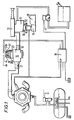
- Figure 1 shows a dual fuel supply system which is operable to supply metered quantities of either petrol or gaseous LPG to an induction passage 10 of a carburetter 11 at a location in that induction passage 10 upstream of a driver-operable throttle valve 12 in that passage 10 for mixture in that passage 10 with air which is drawn into the induction passage 10 through an air cleaner 13 by operation of a multi-cylinder internal combustion engine 20 to which the carburetter 11 is fitted, the carburetter induction passage 10 being in communication with the inlet manifold 15 of the engine 20.
- the present invention is concerned with the arrangement of the gaseous LPG injection means of the system shown in Figure 1 and operation of the gaseous fuel injection means to supply metered quantities of gaseous LPG to the carburetter induction passage 10. Accordingly, the following description will be concerned only with those parts of the system shown in Figure 1.
- Gaseous LPG injection means of the system shown in Figure 1 comprise an assembly 16 of injection valves having a common inlet 17 to which the supply of gaseous LPG at a regulated superatmospheric pressure is fed, and a common outlet 18 which is in conduit communication with the carburetter induction passage 10 through the air cleaner 13.
- the system shown in Figure 1 also includes an electronic control unit 19 which is generally similar to the electronic control unit of the system described in EP-A-0084219 in that it is a microprocessor based unit incorporating a memory matrix which is adapted to be addressed by signals indicative of the two main parameters of engine speed and absolute pressure in the inlet manifold of the engine and which stores pulse width information so that its output at any one instant is a pulse width signal which is the stored pulse width signal for the conditions of engine speed and engine inlet manifold absolute pressure prevailing.
- the electrical control unit 19 incorporates certain features not described in EP-A-0084219 and those differences will be described.
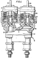
- Figures 2-4 show that the injection valve assembly 16 comprises two electromagnetic injection valves 21 and 22 mounted side by side in a common body 23.
- Each injection valve 21, 22 controls communication between a chamber 24 formed in the body 23 and a common outlet chamber 26.
- the common inlet 17 communicates with the chamber 24.
- the common outlet 18 communicates with the outlet chamber 26.
- the construction of the injection valve 21 will be described now with reference to Figure 3.
- the construction of the injection valve 22 is similar to that of the injection valve 21 and its parts will be identified in the following description by the reference numerals used to identify the corresponding parts of the injection valve 21, but they will be distinguished from the corresponding parts of the injection valve 21 by the addition of the suffix "A".
- Communication between the chamber 24 and the common outlet chamber 26 is via a respective one of two tubular bodies 28 and 28A, each of which is spigotted into a respective bore which extends between the chamber 24 and the outlet chamber 26.
- the tubular bodies 28 and 28A project into the chamber 24.
- An 0-ring 29, 29A is mounted in an annular shoulder formed at the end of the bore of each tubular body 28, 28A within the chamber 24.
- the 0-ring 29, 29A serves as a valve seat.
- a plunger 31, 31A is a sliding fit in a respective bore 32, 32A which is formed coaxially with the bore of the respective tubular body 28, 28A in the portion of the wall of the chamber 24 that faces the 0-ring 29 and 29A.
- each plunger 31, 31A nearer the respective tubular body 28, 28A is formed to seat on that 0-ring 29, 29A and each plunger 31, 31A is spring loaded by a respective spring 33, 33A to seat on the respective 0-ring 29, 29A and thereby close communication between the chambers 24 and 26.
- Each plunger 31, 31A is sufficiently long to project from the end of the respective bore 32, 32A that is further from the tubular body 28, 28A, even when it is seated on the O-ring 29. It has a radial flange 34, 34A at its end that is further from the respective tubular body 28, 28A.
- the radial flange 34, 34A slides within the bore of an annular solenoid core 35, 35A which carries solenoid windings 36, 36A which are connected between terminals 37 and 38, 37A and 38A.
- One of the terminals say the terminal 37, 37A is connected to the respective signal output of the electrical control unit 19, and the other terminal 38, 38A is earthed.
- the solenoid winding 36, 36A of the injection valve 21, 21A is energised for the duration of each pulse of the respective pulsed signal received from a respective solenoid drive circuit 39, 39A (see Figure 5) which is incorporated in the electrical control unit 19.
- Energisation of the solenoid winding 36, 36A unseats the respective plunger 31, 31A so that, for the duration of each pulse, communication is established between the chamber 24 and the outlet chamber 26 so that a volume of gaseous LPG related to the duration of the energising pulse is allowed to flow through the bore of the respective tubular body 28, 28A and the chamber to the common outlet 18.
- the plunger 31, 31A is reseated at the end of each pulse by the action of the respective coil spring 33, 33A.
- FIG. 5 shows that the electronic control unit receives signal indications of the main operating parameters of the engine 20 from respective transducers.
- a pressure transducer 41 which conveniently is mounted in the control unit 19 and is in communication with the inlet manifold 15 by a length of tubing 42, senses pressure in the inlet manifold 15 of the engine and derives therefrom an output signal indicative of the absolute pressure prevailing in the inlet manifold 15 which is a function of engine loading.
- An engine speed signal is derived from the vehicle ignition circuit by a suitable device 43, which may be a four vane switch of a Hall-effect distributor.
- An air flow meter 44 responsive to air flow to the engine through the induction passage 10 generates a signal indicative of that air flow.
- a temperature sensitive device 45 responsive to the engine cooling water temperature provides a signal indicative of that temperature.
- An air temperature sensor 46 provides a signal indicative of air temperature.
- a device 47 provides a signal which is indicative of the voltage output of the vehicle battery.
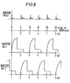
- the engine speed signal derived from the vehicle ignition circuit by the device 43 is shown at the top of Figure 6 and is fed via a pulse shaper 48 directly to a central processing unit 54 of a microprocessor 51.
- the signals from the other transducers 41 and 44-47 are fed to an in/out control device of the microprocessor 51 via a multiplexer 52 and an analogue to digital converter (A/D) 53.
- A/D analogue to digital converter
- the microprocessor 51 is connected to an erasable programmable read only memory (EPROM) 56 which is a memory matrix or look-up table which is operable under the control of the microprocessor 51.
- EPROM erasable programmable read only memory
- the microprocessor 51 has two signal outputs and is arranged to emit output pulse signals alternately from either output as described more fully in co-pending Patent Application No..83307236.6. Each output of the microprocessor 51 is connected to a respective one of the two solenoid drive circuits 39 and 39A.
- the EPROM 56 is addressed, under control of the central processing unit 54, by signals indicative of the two main parameters of engine speed and absolute pressure in the inlet manifold of the engine and fuel metering pulses are developed and are emitted from the signal outputs alternately to either of the solenoid drive circuits 39 and 39A.
- the output pulses emitted by the microprocessor assembly 51 and transmitted alternately to the solenoid drive circuits 39 and 39A are synchronised with the ignition firing sequence of the engine 20 so that the solenoid winding 36, 36A of each injection valve 21, 22 is energised once for every other ignition firing of the engine.
- the width of each fuel metering pulse determines the duration of the drive pulse from the solenoid drive circuit 39, 39A and the amount of fuel delivered by each injection.
- FIG 6 shows the relationship between the ignition firing sequence, which is shown at the top, and the solenoid energising pulses emitted by the respective solenoid drive circuits 39, 39A.
- Each solenoid energising pulse has a rising leading edge leading to a drive current of approximately 4 amps which is effective to displace the valve plunger 31, 31A from its seat 29, 29A, followed by a steady portion of approximately 1 amp during which the valve plunger 31, 31A is in its open position.
- Figure 4 shows the valve plunger 31 unseated whilst the valve plunger 31A is seated.
- valves Although the solenoid energising pulses cause the valves to open alternately at equivalent points in the engine cycle on alternate cylinder firings, it will be understood from Figure 6 that under certain engine operating conditions, e.g. at higher engine speeds, one valve may remain open whilst the other has opened.
- the two injection valves 21 and 22 are operated sequentially by the electrical control unit 19 so that the pulsed outputs from those two valves are collected in the common outlet chamber 26.
- the injection valve assembly 16 emits gaseous LPG from its common outlet 18 at a frequency which is synchronised with engine speed.
- the resultant gaseous LPG supply may be a pulsed output at lower engine speeds and may merge into a substantially continuous stream at higher engine speeds.
- the output of gaseous LPG from the common outlet 18 is conveyed to the carburettor induction passage 10 and is introduced to the interior of the induction passage 10 through the air cleaner 13 whereby it is presented to the air flow through the induction passage 10 to the engine as a single supply of gaseous fuel.
- the injection valve assembly 16 is conveniently situated to avoid excessive heating of the injection valves and it is conveniently mounted so as to minimise operating noise.
- the memory matrix 56 incorporated in the electrical control unit 19 conveniently consists of two hundred and fifty six values of pulse width in a range of 0 to 10 milliseconds. Between each value location, a process of arithmetic linear interpolation is to be applied in sixteen steps.
- the engine speed address steps are applied to the memory matrix 56 on a geometric series to provide suitable sensitivity for low values.
- the engine load address may be arithmetic steps.
- the moment of injection may be phase delayed after each instant of ignition firing by the inclusion of a delay device 58, 58A, between the microprocessor 51 and each solenoid drive circuit 39, 39A as shown in Figure 7.
- Various means for modifying the pulse width output signal from the microprocessor assembly 51 may be provided in the electrical control unit 19 for various reasons.
- zero values may be placed in the matrix at engine load addresses below a predetermined minimum absolute manifold pressure, say 0.2 bar.
- An independent pulse width generator 59 (See Figure 8) responsive to the ignition pulse signal, or other engine speed signal, may be used to give very large pulse widths in the region of 75 milliseconds synchronised to the engine cranking speed for engine cranking.
- the values may need to be modified with engine coolant temperature.
- provision may be made for protecting against excessive gas being delivered during cranking in the event of the engine failing to start. This may be achieved by incorporating in a signal source that would serve as the generator 59, means for reducing the cranking pulse width from the initial large pulse width of say 75 milliseconds to zero over a period of twenty seconds cranking.
- the two injection valves 21 and 22 need not be mounted side by side as shown in Figures 2 and 4. They may be mounted substantially coaxially so that they inject towards one another, or in a vee arrangement so that they inject along convergent paths. Alternatively, they may be staggered, being displaced laterally relative to one another and arranged to inject in opposite directions along parallel paths into passages which are interconnected.
- Figure 9 illustrates an alternative form of injection valve for use instead of the plunger type injection valve described above with reference to Figures 2 to 4.
- the plunger type injection valve 21 communication between the chamber 24 and the outlet chamber 26 is through the bore of a tubular body 28.
- Figure 9 shows that the bore is stepped, reducing in diameter in the downstream direction whereas the diameter of the stepped bore of the tubular body 28 of the plunger type injection valve 21 increases in the downstream direction.
- the valve member of the injection valve shown in Figure 9 is a disc 61 which has a central flat surface of a larger diameter than the diameter of the O-ring 29 with which it co-operates to close communication between the chambers 24 and 26.
- a spring 62 which is located in a bore 63 formed in the body 23 coaxially with the bore of the tubular body 28, acts through a ball 64 to urge the disc 61 to seat on the 0-ring 29 and close communication between the chamber 24 and the chamber 26.
- the ball 64 is also located in the bore 63.
- the disc 61 is unseated, as shown in Figure 9, when the solenoid winding 36 is energised by a pulse signal received from the electrical control unit 19.
- the moving parts of the valve shown in Figure 9, viz. the disc 61 and the ball 64, may be lighter than corresponding parts of the plunger type valve 21 so that the disc type valve may be operated at a higher frequency than the plunger type valve.
- Such a multiple injection valve assembly which is operated sequentially in synchronism with operation of an engine and which has its metered pulsed outputs collected and fed as a single supply for presentation to a stream of air which is inducted into the engine, is not limited in its application to dual petrol/LPG systems. It is applicable to any gaseous fuel system for a multi-cylinder i.c. engine where the metered supply of gaseous fuel is mixed with a stream of air which is inducted to an i.c. engine through an induction passage having a driver operable throttle valve in it for controlling flow of the air/fuel mixture to the engine.
Landscapes
- Engineering & Computer Science (AREA)
- Chemical & Material Sciences (AREA)
- Combustion & Propulsion (AREA)
- Mechanical Engineering (AREA)
- General Engineering & Computer Science (AREA)
- Chemical Kinetics & Catalysis (AREA)
- General Chemical & Material Sciences (AREA)
- Oil, Petroleum & Natural Gas (AREA)
- Analytical Chemistry (AREA)
- Output Control And Ontrol Of Special Type Engine (AREA)
- Electrical Control Of Air Or Fuel Supplied To Internal-Combustion Engine (AREA)
Applications Claiming Priority (4)
| Application Number | Priority Date | Filing Date | Title |
|---|---|---|---|
| GB8234310 | 1982-12-01 | ||
| GB8234310 | 1982-12-01 | ||
| GB8235448 | 1982-12-13 | ||
| GB8235448 | 1982-12-13 |
Publications (1)
| Publication Number | Publication Date |
|---|---|
| EP0112089A1 true EP0112089A1 (fr) | 1984-06-27 |
Family
ID=26284553
Family Applications (2)
| Application Number | Title | Priority Date | Filing Date |
|---|---|---|---|
| EP83307236A Withdrawn EP0110699A1 (fr) | 1982-12-01 | 1983-11-28 | Système d'induction de mélange dans un moteur à combustion interne, à plusieurs cylindres |
| EP83307277A Withdrawn EP0112089A1 (fr) | 1982-12-01 | 1983-11-29 | Système d'admission d'un mélange air-carburant pour moteur à combustion interne à plusieurs cylindres |
Family Applications Before (1)
| Application Number | Title | Priority Date | Filing Date |
|---|---|---|---|
| EP83307236A Withdrawn EP0110699A1 (fr) | 1982-12-01 | 1983-11-28 | Système d'induction de mélange dans un moteur à combustion interne, à plusieurs cylindres |
Country Status (2)
| Country | Link |
|---|---|
| US (2) | US4545345A (fr) |
| EP (2) | EP0110699A1 (fr) |
Cited By (1)
| Publication number | Priority date | Publication date | Assignee | Title |
|---|---|---|---|---|
| EP0157430A3 (en) * | 1984-04-04 | 1987-07-08 | Medardo Reggiani | Injection unit for internal combustion engines fed with gaseous fuels such as liquefied petroleum gas or methane |
Families Citing this family (58)
| Publication number | Priority date | Publication date | Assignee | Title |
|---|---|---|---|---|
| EP0183879A1 (fr) * | 1984-12-05 | 1986-06-11 | 317921 Alberta Ltd. | Système de régulation électronique du débit d'un fluide |
| JPS61229947A (ja) * | 1985-04-02 | 1986-10-14 | Nippon Soken Inc | デイ−ゼルエンジンの燃料噴射制御装置 |
| AT384279B (de) * | 1986-03-05 | 1987-10-27 | Jenbacher Werke Ag | Einrichtung zur regelung des verbrennungsluftverh|ltnisses bei einem gasmotor mit magerer betriebsweise |
| DE3612994A1 (de) * | 1986-04-17 | 1987-10-29 | Hi Tec Gas International Gmbh | Dosiervorrichtung fuer gasfoermigen kraftstoff |
| US4846134A (en) * | 1988-03-30 | 1989-07-11 | V. R. Systems, Inc. | Apparatus and method for removing and burning hydrocarbon vapors using an internal combustion engine |
| NL8801554A (nl) * | 1988-06-17 | 1990-01-16 | Necam Bv | Intelligente besturing van autogasapparatuur. |
| JPH0223258A (ja) * | 1988-07-11 | 1990-01-25 | Yamaha Motor Co Ltd | ガスエンジン |
| US4953515A (en) * | 1988-11-28 | 1990-09-04 | Fehr William A | Diesel engine secondary fuel injection system |
| JPH03107568A (ja) * | 1989-09-22 | 1991-05-07 | Aisin Seiki Co Ltd | 燃料噴射装置 |
| CA1326794C (fr) * | 1989-09-29 | 1994-02-08 | Ortech Corporation | Systeme de regulation du debit |
| US5010868A (en) * | 1990-04-03 | 1991-04-30 | Jerry Clements | Gas-phase propane fuel delivery system |
| DE4020453A1 (de) * | 1990-06-27 | 1992-01-02 | Motoren Werke Mannheim Ag | Gasmotor |
| WO1992008886A1 (fr) * | 1990-11-20 | 1992-05-29 | Biocom Pty. Ltd. | Procede d'injection de carburant |
| US5101794A (en) * | 1991-07-22 | 1992-04-07 | Blaricom Terry M Van | Internal combustion engine |
| US5203305A (en) * | 1991-09-11 | 1993-04-20 | Porter Fred C | Apparatus and methods for converting conventionally fueled engines to operate on an alternative fuel |
| US5150685A (en) * | 1991-09-11 | 1992-09-29 | Porter Fred C | Apparatus and method for converting conventionally fueled engines to operate on an alternative fuel |
| US5237981A (en) * | 1992-02-21 | 1993-08-24 | Pas, Inc. | Fuel injection apparatus for vehicles |
| US5322046A (en) * | 1992-10-08 | 1994-06-21 | Microfuels, Inc. | Electronic fuel injector control for rotary vacuum fuel conversion device |
| US5275145A (en) * | 1992-12-07 | 1994-01-04 | Walbro Corporation | Vapor recovery system for motor vehicles |
| US5411058A (en) * | 1992-12-22 | 1995-05-02 | Welsh; James W. | Method and apparatus for utilizing gaseous and liquid fuels in an internal combustion device |
| US5378114A (en) * | 1993-02-01 | 1995-01-03 | Howe; William H. | Gaseous fuel injection pump |
| US5408978A (en) * | 1993-05-03 | 1995-04-25 | Davis Family Trust | Gaseous fuel entrainment apparatus and process |
| US5325838A (en) * | 1993-05-28 | 1994-07-05 | Bennett David E | Liquified petroleum gas fuel injector |
| US5329908A (en) * | 1993-06-08 | 1994-07-19 | Cummins Engine Company, Inc. | Compressed natural gas injection system for gaseous fueled engines |
| EP0748417B1 (fr) | 1994-02-15 | 2001-11-21 | Invent Engineering Pty. Ltd. | Systeme d'injection electronique de carburant a commande hydraulique |
| US5450832A (en) * | 1994-03-21 | 1995-09-19 | Bruce R. Graf | Dual fuel system |
| JP3360955B2 (ja) * | 1994-11-14 | 2003-01-07 | ヤマハ発動機株式会社 | ガス燃料エンジンの燃料供給装置 |
| US5533480A (en) * | 1995-06-07 | 1996-07-09 | Mtn International, Llc | Low force actuatable fuel injector |
| US5671711A (en) * | 1995-12-07 | 1997-09-30 | Ford Global Technologies, Inc. | Low pressure LPG vapor fuel injection |
| AU7377798A (en) | 1997-05-13 | 1998-12-08 | Bennett Technologies, L.L.C. | Liquefied petroleum gas fuel system and method |
| IT1297323B1 (it) * | 1997-10-20 | 1999-09-01 | Emer Srl | Apparecchiatura di controllo dell'erogazione del gas in impianti a gas per autotrazione |
| US6250260B1 (en) * | 1998-10-13 | 2001-06-26 | Jason E. Green | Bi-fuel control system and assembly for reciprocating diesel engine powered electric generators |
| US6227173B1 (en) | 1999-06-07 | 2001-05-08 | Bi-Phase Technologies, L.L.C. | Fuel line arrangement for LPG system, and method |
| US6422015B2 (en) * | 2000-07-13 | 2002-07-23 | Keith A. Long | Propane injection system and method for a diesel engine |
| US6609496B1 (en) | 2000-12-01 | 2003-08-26 | Caterpillar Inc | Engine controller for an internal combustion engine |
| CN1093595C (zh) * | 2000-12-28 | 2002-10-30 | 上海交通大学 | 双燃料汽车双达标低排放控制系统 |
| US6619139B2 (en) | 2001-02-16 | 2003-09-16 | Enginuity, Llc | Gas flow sensor and high pressure gaseous fuel injection system |
| US9528447B2 (en) | 2010-09-14 | 2016-12-27 | Jason Eric Green | Fuel mixture control system |
| US9248736B2 (en) | 2011-09-16 | 2016-02-02 | Gaseous Fuel Systems, Corp. | Modification of an industrial vehicle to include a containment area and mounting assembly for an alternate fuel |
| US8882071B2 (en) | 2011-09-16 | 2014-11-11 | Jason Green | Modification of an industrial vehicle to include a containment area and mounting assembly for an alternate fuel |
| US10086694B2 (en) | 2011-09-16 | 2018-10-02 | Gaseous Fuel Systems, Corp. | Modification of an industrial vehicle to include a containment area and mounting assembly for an alternate fuel |
| US9421861B2 (en) | 2011-09-16 | 2016-08-23 | Gaseous Fuel Systems, Corp. | Modification of an industrial vehicle to include a containment area and mounting assembly for an alternate fuel |
| US8820289B2 (en) | 2011-09-27 | 2014-09-02 | Jason Green | Module containment of fuel control system for a vehicle |
| US9278614B2 (en) | 2011-10-17 | 2016-03-08 | Gaseous Fuel Systems, Corp. | Vehicle mounting assembly for a fuel supply |
| US8881933B2 (en) | 2011-10-17 | 2014-11-11 | Jason E. Green | Vehicle mounting assembly for a fuel supply |
| US9738154B2 (en) | 2011-10-17 | 2017-08-22 | Gaseous Fuel Systems, Corp. | Vehicle mounting assembly for a fuel supply |
| US9696066B1 (en) | 2013-01-21 | 2017-07-04 | Jason E. Green | Bi-fuel refrigeration system and method of retrofitting |
| US20150025774A1 (en) | 2013-07-22 | 2015-01-22 | Jason Green | Fuel mixture system and assembly |
| US9845744B2 (en) | 2013-07-22 | 2017-12-19 | Gaseous Fuel Systems, Corp. | Fuel mixture system and assembly |
| US9394841B1 (en) | 2013-07-22 | 2016-07-19 | Gaseous Fuel Systems, Corp. | Fuel mixture system and assembly |
| US9464588B2 (en) | 2013-08-15 | 2016-10-11 | Kohler Co. | Systems and methods for electronically controlling fuel-to-air ratio for an internal combustion engine |
| DE102014205454A1 (de) * | 2014-03-24 | 2015-09-24 | Robert Bosch Gmbh | Gasinjektor mit Doppelventilnadel |
| US9254849B1 (en) | 2014-10-07 | 2016-02-09 | Gaseous Fuel Systems, Corp. | Device and method for interfacing with a locomotive engine |
| US10054081B2 (en) | 2014-10-17 | 2018-08-21 | Kohler Co. | Automatic starting system |
| US9931929B2 (en) | 2014-10-22 | 2018-04-03 | Jason Green | Modification of an industrial vehicle to include a hybrid fuel assembly and system |
| US9428047B2 (en) | 2014-10-22 | 2016-08-30 | Jason Green | Modification of an industrial vehicle to include a hybrid fuel assembly and system |
| US9885318B2 (en) | 2015-01-07 | 2018-02-06 | Jason E Green | Mixing assembly |
| DE102015104799B4 (de) * | 2015-03-27 | 2016-10-20 | Mesa Parts GmbH | Ventilanordnung, Verwendung einer Ventilanordnung, Baukastensystem zum Aufbau von Ventilanordnungen |
Citations (12)
| Publication number | Priority date | Publication date | Assignee | Title |
|---|---|---|---|---|
| US3001757A (en) * | 1958-04-09 | 1961-09-26 | Chrysler Corp | Magnetic fuel injection nozzle |
| US3742920A (en) * | 1971-09-27 | 1973-07-03 | Brico Eng | Fuel injection systems |
| FR2188059A1 (fr) * | 1972-06-07 | 1974-01-18 | Nissan Motor | |
| US4032755A (en) * | 1974-06-18 | 1977-06-28 | The Lucas Electrical Company Limited | Process control apparatus |
| FR2349741A1 (fr) * | 1976-04-29 | 1977-11-25 | Bauche Henri | Appareil pour l'alimentation d'un moteur a explosion |
| GB2014336A (en) * | 1978-01-19 | 1979-08-22 | Bedford T J | Internal Combustion Engine Utilising Liquefied Gaseous Fuel |
| FR2431031A1 (fr) * | 1978-07-13 | 1980-02-08 | Mitsubishi Motors Corp | Dispositif d'alimentation en carburant pour un moteur |
| US4200064A (en) * | 1977-04-27 | 1980-04-29 | Fabbrica Italiana Magneti Marelli S.P.A. | Electronic apparatus for feed control of air-gasoline mixture in internal combustion engines |
| GB2053511A (en) * | 1979-06-27 | 1981-02-04 | Gen Motors Corp | Automatic control of fuel supply in ic engines |
| WO1981000282A1 (fr) * | 1979-07-13 | 1981-02-05 | G Costa | Systeme d'alimentation en combustible pour moteurs a combustion interne |
| FR2472664A1 (fr) * | 1979-12-07 | 1981-07-03 | Citroen Sa | Dispositif pour le demarrage d'un moteur a combustion interne alimente en gaz liquefie |
| EP0034076A2 (fr) * | 1980-02-01 | 1981-08-19 | The Bendix Corporation | Système d'activation de solénoide |
Family Cites Families (15)
| Publication number | Priority date | Publication date | Assignee | Title |
|---|---|---|---|---|
| US3664315A (en) * | 1970-03-16 | 1972-05-23 | Allied Chem | Lp-gas ram-air charger |
| US3780711A (en) * | 1971-12-16 | 1973-12-25 | Acf Ind Inc | Electronic fuel injection system |
| US3971348A (en) * | 1974-05-08 | 1976-07-27 | International Harvester Company | Computer means for sequential fuel injection |
| JPS5343616B2 (fr) * | 1974-07-19 | 1978-11-21 | ||
| US4086884A (en) * | 1976-06-14 | 1978-05-02 | Ford Motor Company | Method and apparatus for controlling the amount of fuel metered into an internal combustion engine |
| JPS5331030A (en) * | 1976-09-03 | 1978-03-23 | Nissan Motor Co Ltd | Mixture controller |
| FR2370216A1 (fr) * | 1976-11-05 | 1978-06-02 | Renault | Dispositif de commande par programme de courant de plusieurs electrovannes a fonctionnement asynchrone simultane ou non |
| JPS5382927A (en) * | 1976-12-28 | 1978-07-21 | Nissan Motor Co Ltd | Air-fuel ratio controlling apparatus |
| US4204507A (en) * | 1977-03-17 | 1980-05-27 | The Bendix Corporation | Fuel electric fuel injection valve |
| JPS5425330A (en) * | 1977-07-28 | 1979-02-26 | Nippon Denso Co Ltd | Electronically controlled fuel injector for engine with odd number of cylinders |
| WO1980000033A1 (fr) * | 1978-06-07 | 1980-01-10 | E Phillips | Tambour pour bande abrasive |
| JPS5768537A (en) * | 1980-10-17 | 1982-04-26 | Nissan Motor Co Ltd | Fuel controller |
| US4430978A (en) * | 1981-09-28 | 1984-02-14 | The Bendix Corporation | Direct liquid injection of liquid petroleum gas |
| US4421087A (en) * | 1982-02-05 | 1983-12-20 | Schuurman Eiko A | Alternative liquid fuel injection system and method |
| US4450821A (en) * | 1982-09-13 | 1984-05-29 | Vcd Fuel Systems | Gaseous fuel delivery system |
-
1983
- 1983-11-28 US US06/555,406 patent/US4545345A/en not_active Expired - Fee Related
- 1983-11-28 US US06/555,481 patent/US4617904A/en not_active Expired - Fee Related
- 1983-11-28 EP EP83307236A patent/EP0110699A1/fr not_active Withdrawn
- 1983-11-29 EP EP83307277A patent/EP0112089A1/fr not_active Withdrawn
Patent Citations (12)
| Publication number | Priority date | Publication date | Assignee | Title |
|---|---|---|---|---|
| US3001757A (en) * | 1958-04-09 | 1961-09-26 | Chrysler Corp | Magnetic fuel injection nozzle |
| US3742920A (en) * | 1971-09-27 | 1973-07-03 | Brico Eng | Fuel injection systems |
| FR2188059A1 (fr) * | 1972-06-07 | 1974-01-18 | Nissan Motor | |
| US4032755A (en) * | 1974-06-18 | 1977-06-28 | The Lucas Electrical Company Limited | Process control apparatus |
| FR2349741A1 (fr) * | 1976-04-29 | 1977-11-25 | Bauche Henri | Appareil pour l'alimentation d'un moteur a explosion |
| US4200064A (en) * | 1977-04-27 | 1980-04-29 | Fabbrica Italiana Magneti Marelli S.P.A. | Electronic apparatus for feed control of air-gasoline mixture in internal combustion engines |
| GB2014336A (en) * | 1978-01-19 | 1979-08-22 | Bedford T J | Internal Combustion Engine Utilising Liquefied Gaseous Fuel |
| FR2431031A1 (fr) * | 1978-07-13 | 1980-02-08 | Mitsubishi Motors Corp | Dispositif d'alimentation en carburant pour un moteur |
| GB2053511A (en) * | 1979-06-27 | 1981-02-04 | Gen Motors Corp | Automatic control of fuel supply in ic engines |
| WO1981000282A1 (fr) * | 1979-07-13 | 1981-02-05 | G Costa | Systeme d'alimentation en combustible pour moteurs a combustion interne |
| FR2472664A1 (fr) * | 1979-12-07 | 1981-07-03 | Citroen Sa | Dispositif pour le demarrage d'un moteur a combustion interne alimente en gaz liquefie |
| EP0034076A2 (fr) * | 1980-02-01 | 1981-08-19 | The Bendix Corporation | Système d'activation de solénoide |
Cited By (1)
| Publication number | Priority date | Publication date | Assignee | Title |
|---|---|---|---|---|
| EP0157430A3 (en) * | 1984-04-04 | 1987-07-08 | Medardo Reggiani | Injection unit for internal combustion engines fed with gaseous fuels such as liquefied petroleum gas or methane |
Also Published As
| Publication number | Publication date |
|---|---|
| US4545345A (en) | 1985-10-08 |
| EP0110699A1 (fr) | 1984-06-13 |
| US4617904A (en) | 1986-10-21 |
Similar Documents
| Publication | Publication Date | Title |
|---|---|---|
| US4617904A (en) | Air/fuel induction system for a multi-cylinder internal combustion engine | |
| US4541383A (en) | Method and apparatus for minimum knock operation of an internal combustion engine on low knock-rated fuel | |
| US4020803A (en) | Combined fuel injection and intake valve for electronic fuel injection engine systems | |
| US5755211A (en) | Apparatus for operating an internal combustion engine with various fuels | |
| KR940004362B1 (ko) | 연료 전달 방법 | |
| US5477830A (en) | Electronic fuel injection system for internal combustion engines having a common intake port for each pair of cylinders | |
| US5311430A (en) | Vehicle operation data recording apparatus | |
| US9506441B2 (en) | Apparatus and method for measuring a fluid vapour in a pumping chamber | |
| US2980090A (en) | Fuel injection system | |
| JP2550026B2 (ja) | 内燃機関の液体燃料分配方法および分配装置 | |
| US5343847A (en) | Electronic gaseous fuel injection system | |
| US10161318B2 (en) | System, method, and apparatus for injecting a gas in a diesel engine | |
| WO1980000267A1 (fr) | Dispositif d'injection de combustible pour moteur a combustion interne | |
| GB1399391A (en) | Fuel injection systems | |
| WO1989000640A1 (fr) | Ameliorations apportees a l'injection de carburant | |
| JPS58160520A (ja) | 内燃機関用燃料噴射装置 | |
| US4372278A (en) | High temperature and high pressure fuel injection apparatus for internal combustion engines | |
| US5671711A (en) | Low pressure LPG vapor fuel injection | |
| US4373491A (en) | Fuel supply system | |
| US5803057A (en) | Method and apparatus for dosing a gaseous fuel | |
| US4387696A (en) | Electromagnetically controlled fuel injection system | |
| EP1105634A1 (fr) | Procede de controle d'un systeme d'alimentation par injection | |
| US5341785A (en) | Fuel delivery system for internal combustion engines | |
| US4694808A (en) | Method and fuel injection system for fuel supply to a mixture-compressing internal combustion engine having externally supplied ignition | |
| EP0065288B1 (fr) | Dispositif d'alimentation ou injection de carburant pour un moteur à plusieurs cylindres |
Legal Events
| Date | Code | Title | Description |
|---|---|---|---|
| PUAI | Public reference made under article 153(3) epc to a published international application that has entered the european phase |
Free format text: ORIGINAL CODE: 0009012 |
|
| AK | Designated contracting states |
Designated state(s): AT BE CH DE FR GB IT LI LU NL SE |
|
| 17P | Request for examination filed |
Effective date: 19840823 |
|
| RAP1 | Party data changed (applicant data changed or rights of an application transferred) |
Owner name: SOLEX (U.K.) LIMITED - IN LIQUIDATION |
|
| STAA | Information on the status of an ep patent application or granted ep patent |
Free format text: STATUS: THE APPLICATION HAS BEEN WITHDRAWN |
|
| 18W | Application withdrawn |
Withdrawal date: 19910311 |
|
| R18W | Application withdrawn (corrected) |
Effective date: 19910311 |
|
| RIN1 | Information on inventor provided before grant (corrected) |
Inventor name: PAGDIN, BRIAN COLIN |