EP0112092A1 - Aubes de turbine avec bande de couverture intégrée et méthode d'assemblage des aubes dans un cercle - Google Patents
Aubes de turbine avec bande de couverture intégrée et méthode d'assemblage des aubes dans un cercle Download PDFInfo
- Publication number
- EP0112092A1 EP0112092A1 EP83307294A EP83307294A EP0112092A1 EP 0112092 A1 EP0112092 A1 EP 0112092A1 EP 83307294 A EP83307294 A EP 83307294A EP 83307294 A EP83307294 A EP 83307294A EP 0112092 A1 EP0112092 A1 EP 0112092A1
- Authority
- EP
- European Patent Office
- Prior art keywords
- blades
- planar surface
- blade
- circular array
- trailing
- Prior art date
- Legal status (The legal status is an assumption and is not a legal conclusion. Google has not performed a legal analysis and makes no representation as to the accuracy of the status listed.)
- Granted
Links
Images
Classifications
-
- F—MECHANICAL ENGINEERING; LIGHTING; HEATING; WEAPONS; BLASTING
- F01—MACHINES OR ENGINES IN GENERAL; ENGINE PLANTS IN GENERAL; STEAM ENGINES
- F01D—NON-POSITIVE DISPLACEMENT MACHINES OR ENGINES, e.g. STEAM TURBINES
- F01D5/00—Blades; Blade-carrying members; Heating, heat-insulating, cooling or antivibration means on the blades or the members
- F01D5/12—Blades
- F01D5/22—Blade-to-blade connections, e.g. for damping vibrations
- F01D5/225—Blade-to-blade connections, e.g. for damping vibrations by shrouding
-
- F—MECHANICAL ENGINEERING; LIGHTING; HEATING; WEAPONS; BLASTING
- F05—INDEXING SCHEMES RELATING TO ENGINES OR PUMPS IN VARIOUS SUBCLASSES OF CLASSES F01-F04
- F05D—INDEXING SCHEME FOR ASPECTS RELATING TO NON-POSITIVE-DISPLACEMENT MACHINES OR ENGINES, GAS-TURBINES OR JET-PROPULSION PLANTS
- F05D2250/00—Geometry
- F05D2250/10—Two-dimensional
- F05D2250/14—Two-dimensional elliptical
- F05D2250/141—Two-dimensional elliptical circular
Definitions
- This invention relates to steam turbines and in particular to a plurality of rotatable blades arranged in a circular array in a steam turbine rotor.
- a plurality of rotatable blades are arranged in a circular array on a steam turbine rotor, said blades comprising a root portion which fastens said blades to said rotor, an air foil shaped blade portion having a leading edge and a trailing edge and a shroud portion made integral with the blade portion and disposed on the radially outer end of the blade portion, said shroud portion having a leading planar surface and a trailing planar surface, one of which is disposed substantially parallel to an axial radial plane passing through the central portion of the root portion and the other planar surface if extended forms an angle with said axial radial plane substantially equal in degrees to 360 divided by the number of blades forming said circular array.
- the blades have a root portion, which fasten the blades to the rotor, an air foiled shaped blade portion having a leading edge and a trailing edge, and a shroud portion made integral with the blade portion and disposed on the radially outer end of the blade portion.
- the shroud portion has a leading planar surface and a trailing planar surface.
- the leading planar surface is disposed generally parallel to an axial radial plane passing through the central portion of the root portion and the trailing planar surface if extended forms an angle with the radial axial plane passing through the center of the root portion generally equal in degrees to 360 divided by the number of blades forming the circular array.
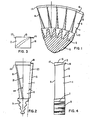
- Extending radially outwardly from the root portion 5 is an air foiled shaped blade portion 9 having leading and trailing edges 11 and 13, respectively.
- a shroud portion 15 Disposed radially outwardly of the blade portion 9 and made integral therewith is a shroud portion 15.
- the shroud portion 15 has a leading planar surface 17 and a trailing planar surface 19.
- the leading planar surface 17 is generally parallel to an axial radial plane 21 passing through the center portion of the root portion 5.
- the trailing planar surface 19 if extended as indicated at 23 forms an angle a with the radial axial plane equal in degrees to 360 divided by the number of blades in the circular array.
- leading planar surface 17 extends a few thousandths of an inch beyond the leading edge of the blade portion 9 and the trailing edge 13 of the blade portion 9 extends substantially beyond the trailing planar surface 19 of the shroud portion 15.
- the outer periphery of the shroud portion 15 is machined to form a cylindrical ring which cooperates with labyrinth seals to form a rotating seal.
- the method of forming the circular array of blades 1 comprises the steps of forming each blade with a shroud portion 15 made integral with a blade portion 9, the shroud portion 15 having a leading planar surface 17 and a trailing planar surface 19; forming the leading planar surface 17 so that it is substantially parallel to an axial radial plane 21 passing through the center portion of the root portion 5, forming the trailing planar surface 19 so that if it were extended, it would form an angle with the axial radial plane passing through the central portion of the root portion 5 equal in degrees to.
- leading planar surface 17 on the shroud 15 360 divided by the number of blades in the circular array, forming the leading planar surface 17 on the shroud 15 so that there is several thousandths of an inch interference when assembling adjacent blades, machining each leading planar surface 17 individually to remove just enough material to allow assembly of the blade adjacent the trailing side of the adjacent blade, so that the blade can be assembled with the centerline of the blade in a radial plane, and machining the outer peripheral surface of the shroud portion 15 of the circular array of blades to form a cylindrical surface which cooperates with a labyrinth seal to form a rotating seal.
- the blades and method form a complete shroud ring greatly reducing blade vibration due to the snubbing and damping of the abutting shroud portions and eliminating riveted tenons, which accumulate corrosive products and are subject to corrosion and stress cracking.
Landscapes
- Engineering & Computer Science (AREA)
- Mechanical Engineering (AREA)
- General Engineering & Computer Science (AREA)
- Turbine Rotor Nozzle Sealing (AREA)
Applications Claiming Priority (2)
| Application Number | Priority Date | Filing Date | Title |
|---|---|---|---|
| US06/446,093 US4533298A (en) | 1982-12-02 | 1982-12-02 | Turbine blade with integral shroud |
| US446093 | 1982-12-02 |
Publications (2)
| Publication Number | Publication Date |
|---|---|
| EP0112092A1 true EP0112092A1 (fr) | 1984-06-27 |
| EP0112092B1 EP0112092B1 (fr) | 1988-11-09 |
Family
ID=23771294
Family Applications (1)
| Application Number | Title | Priority Date | Filing Date |
|---|---|---|---|
| EP83307294A Expired EP0112092B1 (fr) | 1982-12-02 | 1983-11-30 | Aubes de turbine avec bande de couverture intégrée et méthode d'assemblage des aubes dans un cercle |
Country Status (13)
| Country | Link |
|---|---|
| US (1) | US4533298A (fr) |
| EP (1) | EP0112092B1 (fr) |
| JP (1) | JPS59108803A (fr) |
| KR (1) | KR910009708B1 (fr) |
| AU (1) | AU574050B2 (fr) |
| CA (1) | CA1324765C (fr) |
| DE (1) | DE3378419D1 (fr) |
| EG (1) | EG16089A (fr) |
| ES (1) | ES527702A0 (fr) |
| IN (1) | IN161993B (fr) |
| IT (1) | IT1171793B (fr) |
| MX (1) | MX156754A (fr) |
| ZA (1) | ZA838219B (fr) |
Families Citing this family (22)
| Publication number | Priority date | Publication date | Assignee | Title |
|---|---|---|---|---|
| US4711007A (en) * | 1986-09-29 | 1987-12-08 | Westinghouse Electric Corp. | Method and apparatus for installing free standing turbine blades |
| US4718172A (en) * | 1986-09-30 | 1988-01-12 | Westinghouse Electric Corp. | Turbine blade radial position gage |
| US4784571A (en) * | 1987-02-09 | 1988-11-15 | Westinghouse Electric Corp. | Apparatus and method for reducing blade flop in steam turbine |
| US4767273A (en) * | 1987-02-24 | 1988-08-30 | Westinghouse Electric Corp. | Apparatus and method for reducing blade flop in steam turbine |
| US4767247A (en) * | 1987-02-24 | 1988-08-30 | Westinghouse Electric Corp. | Apparatus and method for preventing relative blade motion in steam turbine |
| US4781534A (en) * | 1987-02-27 | 1988-11-01 | Westinghouse Electric Corp. | Apparatus and method for reducing windage and leakage in steam turbine incorporating axial entry blade |
| US4765046A (en) * | 1987-05-22 | 1988-08-23 | Westinghouse Electric Corp. | Row assembly process for integral shroud blades |
| US4815938A (en) * | 1987-12-24 | 1989-03-28 | Westinghouse Electric Corp. | Shroud gap control for integral shrouded blades |
| US4904160A (en) * | 1989-04-03 | 1990-02-27 | Westinghouse Electric Corp. | Mounting of integral platform turbine blades with skewed side entry roots |
| US5277549A (en) * | 1992-03-16 | 1994-01-11 | Westinghouse Electric Corp. | Controlled reaction L-2R steam turbine blade |
| US5238366A (en) * | 1992-07-06 | 1993-08-24 | Westinghouse Electric Corp. | Method and apparatus for determining turbine blade deformation |
| US5352092A (en) * | 1993-11-24 | 1994-10-04 | Westinghouse Electric Corporation | Light weight steam turbine blade |
| JP3034417B2 (ja) * | 1994-02-18 | 2000-04-17 | 株式会社東芝 | 軸流タービンの動翼制振装置 |
| US5540551A (en) * | 1994-08-03 | 1996-07-30 | Westinghouse Electric Corporation | Method and apparatus for reducing vibration in a turbo-machine blade |
| US5524341A (en) * | 1994-09-26 | 1996-06-11 | Westinghouse Electric Corporation | Method of making a row of mix-tuned turbomachine blades |
| US6491498B1 (en) | 2001-10-04 | 2002-12-10 | Power Systems Mfg, Llc. | Turbine blade pocket shroud |
| CN100338337C (zh) * | 2002-06-07 | 2007-09-19 | 三菱重工业株式会社 | 汽轮机转子叶片组件及其组装方法 |
| JP4765882B2 (ja) * | 2006-10-05 | 2011-09-07 | 株式会社日立製作所 | 蒸気タービン動翼 |
| WO2009090908A1 (fr) * | 2008-01-16 | 2009-07-23 | Mitsubishi Heavy Industries, Ltd. | Pale de rotor de turbine |
| EP2762676A1 (fr) * | 2013-02-04 | 2014-08-06 | Siemens Aktiengesellschaft | Aube rotorique de turbomachine, disque de rotor de turbomachine, rotor de turbomachine et moteur à turbine à gaz ayant des surfaces de contact du pied et de la rainure d'aube à angles différents |
| US9683446B2 (en) | 2013-03-07 | 2017-06-20 | Rolls-Royce Energy Systems, Inc. | Gas turbine engine shrouded blade |
| DE102015224375A1 (de) * | 2015-12-04 | 2017-06-08 | Mtu Aero Engines Gmbh | Verfahren zur Prüfung einer Laufschaufeleinheit |
Citations (4)
| Publication number | Priority date | Publication date | Assignee | Title |
|---|---|---|---|---|
| US2221685A (en) * | 1939-01-18 | 1940-11-12 | Gen Electric | Elastic fluid turbine bucket unit |
| GB622019A (en) * | 1946-04-06 | 1949-04-26 | United Aircraft Corp | Improvements in or relating to turbine rotors |
| GB627295A (en) * | 1946-04-10 | 1949-08-05 | Adrian Albert Lombard | Improvements in or relating to the manufacture of guide vanes for axial-flow turbines and compressors |
| GB711572A (en) * | 1951-02-27 | 1954-07-07 | Rateau Soc | Improvements in vibration damping means for bladings in fluid actuated or actuating rotary machines |
Family Cites Families (15)
| Publication number | Priority date | Publication date | Assignee | Title |
|---|---|---|---|---|
| US782132A (en) * | 1904-06-09 | 1905-02-07 | Westinghouse Machine Co | Elastic-fluid turbine. |
| GB210288A (en) * | 1923-02-01 | 1924-01-31 | English Electric Co Ltd | Improvements in the construction of the rotors of elastic fluid turbines |
| BE367869A (fr) * | 1929-02-19 | |||
| US2221679A (en) * | 1939-01-18 | 1940-11-12 | Gen Electric | Method of making elastic fluid turbine buckets |
| US2354587A (en) * | 1942-01-31 | 1944-07-25 | Westinghouse Electric & Mfg Co | Method of manufacturing turbine blades |
| US2510734A (en) * | 1946-04-06 | 1950-06-06 | United Aircraft Corp | Turbine or compressor rotor |
| US2681500A (en) * | 1949-07-18 | 1954-06-22 | Bristol Aeroplane Co Ltd | Method of manufacturing turbine or the like blades |
| DE1159965B (de) * | 1961-08-10 | 1963-12-27 | Bbc Brown Boveri & Cie | Einrichtung zur Schwingungsdaempfung an einem Turbinen- oder Verdichter-Schaufelkranz |
| DE1299004B (de) * | 1965-01-19 | 1969-07-10 | Bbc Brown Boveri & Cie | Einrichtung zur Schwingungsdaempfung an einem Turbinen-oder Verdichterschaufelkranz |
| NL295111A (fr) * | 1962-07-11 | |||
| JPS5135807A (en) * | 1974-09-20 | 1976-03-26 | Fuji Electric Co Ltd | Taabinyoku no seishinsochi |
| DE2617927A1 (de) * | 1976-04-23 | 1977-11-03 | Bbc Brown Boveri & Cie | Stroemungsmaschinenschaufel |
| US4076455A (en) * | 1976-06-28 | 1978-02-28 | United Technologies Corporation | Rotor blade system for a gas turbine engine |
| JPS53143803A (en) * | 1977-05-23 | 1978-12-14 | Mitsubishi Heavy Ind Ltd | Blade construction |
| US4158676A (en) * | 1977-07-08 | 1979-06-19 | Mobil Oil Corporation | Isomerization process |
-
1982
- 1982-12-02 US US06/446,093 patent/US4533298A/en not_active Expired - Fee Related
-
1983
- 1983-10-27 AU AU20641/83A patent/AU574050B2/en not_active Ceased
- 1983-10-29 IN IN1337/CAL/83A patent/IN161993B/en unknown
- 1983-11-03 ZA ZA838219A patent/ZA838219B/xx unknown
- 1983-11-08 IT IT23620/83A patent/IT1171793B/it active
- 1983-11-15 MX MX199411A patent/MX156754A/es unknown
- 1983-11-21 CA CA000441546A patent/CA1324765C/fr not_active Expired - Fee Related
- 1983-11-28 JP JP58222280A patent/JPS59108803A/ja active Pending
- 1983-11-30 EG EG743/83A patent/EG16089A/xx active
- 1983-11-30 DE DE8383307294T patent/DE3378419D1/de not_active Expired
- 1983-11-30 EP EP83307294A patent/EP0112092B1/fr not_active Expired
- 1983-12-01 ES ES527702A patent/ES527702A0/es active Granted
- 1983-12-02 KR KR1019830005703A patent/KR910009708B1/ko not_active Expired
Patent Citations (4)
| Publication number | Priority date | Publication date | Assignee | Title |
|---|---|---|---|---|
| US2221685A (en) * | 1939-01-18 | 1940-11-12 | Gen Electric | Elastic fluid turbine bucket unit |
| GB622019A (en) * | 1946-04-06 | 1949-04-26 | United Aircraft Corp | Improvements in or relating to turbine rotors |
| GB627295A (en) * | 1946-04-10 | 1949-08-05 | Adrian Albert Lombard | Improvements in or relating to the manufacture of guide vanes for axial-flow turbines and compressors |
| GB711572A (en) * | 1951-02-27 | 1954-07-07 | Rateau Soc | Improvements in vibration damping means for bladings in fluid actuated or actuating rotary machines |
Also Published As
| Publication number | Publication date |
|---|---|
| IT8323620A0 (it) | 1983-11-08 |
| DE3378419D1 (en) | 1988-12-15 |
| AU2064183A (en) | 1984-06-07 |
| ES8501837A1 (es) | 1984-12-01 |
| AU574050B2 (en) | 1988-06-30 |
| KR840007130A (ko) | 1984-12-05 |
| EG16089A (en) | 1990-08-30 |
| EP0112092B1 (fr) | 1988-11-09 |
| KR910009708B1 (ko) | 1991-11-25 |
| CA1324765C (fr) | 1993-11-30 |
| MX156754A (es) | 1988-09-29 |
| IT1171793B (it) | 1987-06-10 |
| ES527702A0 (es) | 1984-12-01 |
| ZA838219B (en) | 1984-06-27 |
| US4533298A (en) | 1985-08-06 |
| IN161993B (fr) | 1988-03-12 |
| JPS59108803A (ja) | 1984-06-23 |
Similar Documents
| Publication | Publication Date | Title |
|---|---|---|
| EP0112092A1 (fr) | Aubes de turbine avec bande de couverture intégrée et méthode d'assemblage des aubes dans un cercle | |
| US4602412A (en) | Method for assembling in a circular array turbine blades each with an integral shroud | |
| US4460316A (en) | Blade group with pinned root | |
| US3037742A (en) | Compressor turbine | |
| EP0169801B1 (fr) | Assemblage de plaques de recouvrement d'une turbine | |
| US3576377A (en) | Blades for fluid flow machines | |
| US4130379A (en) | Multiple side entry root for multiple blade group | |
| US4904160A (en) | Mounting of integral platform turbine blades with skewed side entry roots | |
| US4655682A (en) | Compressor stator assembly having a composite inner diameter shroud | |
| EP0169800B1 (fr) | Assemblage d'étanchéification d'une turbine | |
| EP0169799B1 (fr) | Clavette antirotation pour douille à baionnette | |
| US3734646A (en) | Blade fastening means | |
| US3986792A (en) | Vibration dampening device disposed on a shroud member for a twisted turbine blade | |
| US4725200A (en) | Apparatus and method for reducing relative motion between blade and rotor in steam turbine | |
| GB2169664A (en) | Blade root seal | |
| JP2807884B2 (ja) | 回転子組立体 | |
| GB2100809A (en) | Root formation for rotor blade | |
| US4355957A (en) | Blade damper | |
| US2625365A (en) | Shrouded impeller | |
| US2906495A (en) | Turbine blade with corrugated strut | |
| US5486095A (en) | Split disk blade support | |
| US20190368361A1 (en) | Non-symmetric fan blade tip cladding | |
| US2394124A (en) | Bladed body | |
| US3765795A (en) | Compositely formed rotors and their manufacture | |
| JP6554482B2 (ja) | タービンエンジンロータ用の回転対称部品、ならびに関連するタービンエンジンロータ、タービンエンジンモジュール、およびタービンエンジン |
Legal Events
| Date | Code | Title | Description |
|---|---|---|---|
| PUAI | Public reference made under article 153(3) epc to a published international application that has entered the european phase |
Free format text: ORIGINAL CODE: 0009012 |
|
| AK | Designated contracting states |
Designated state(s): BE CH DE FR GB LI SE |
|
| 17P | Request for examination filed |
Effective date: 19841213 |
|
| GRAA | (expected) grant |
Free format text: ORIGINAL CODE: 0009210 |
|
| AK | Designated contracting states |
Kind code of ref document: B1 Designated state(s): BE CH DE FR GB LI SE |
|
| REF | Corresponds to: |
Ref document number: 3378419 Country of ref document: DE Date of ref document: 19881215 |
|
| ET | Fr: translation filed | ||
| PLBI | Opposition filed |
Free format text: ORIGINAL CODE: 0009260 |
|
| PLBI | Opposition filed |
Free format text: ORIGINAL CODE: 0009260 |
|
| 26 | Opposition filed |
Opponent name: SIEMENS AKTIENGESELLSCHAFT, BERLIN UND MUENCHEN Effective date: 19890802 |
|
| 26 | Opposition filed |
Opponent name: ASEA BROWN BOVERI AG Effective date: 19890807 Opponent name: SIEMENS AKTIENGESELLSCHAFT, BERLIN UND MUENCHEN Effective date: 19890802 |
|
| PGFP | Annual fee paid to national office [announced via postgrant information from national office to epo] |
Ref country code: FR Payment date: 19900922 Year of fee payment: 8 |
|
| PGFP | Annual fee paid to national office [announced via postgrant information from national office to epo] |
Ref country code: GB Payment date: 19900925 Year of fee payment: 8 |
|
| PGFP | Annual fee paid to national office [announced via postgrant information from national office to epo] |
Ref country code: SE Payment date: 19900926 Year of fee payment: 8 |
|
| PGFP | Annual fee paid to national office [announced via postgrant information from national office to epo] |
Ref country code: BE Payment date: 19901010 Year of fee payment: 8 |
|
| PGFP | Annual fee paid to national office [announced via postgrant information from national office to epo] |
Ref country code: CH Payment date: 19901219 Year of fee payment: 8 |
|
| PGFP | Annual fee paid to national office [announced via postgrant information from national office to epo] |
Ref country code: DE Payment date: 19901228 Year of fee payment: 8 |
|
| PG25 | Lapsed in a contracting state [announced via postgrant information from national office to epo] |
Ref country code: LI Free format text: LAPSE BECAUSE OF NON-PAYMENT OF DUE FEES Effective date: 19911130 Ref country code: GB Effective date: 19911130 Ref country code: CH Free format text: LAPSE BECAUSE OF NON-PAYMENT OF DUE FEES Effective date: 19911130 Ref country code: BE Effective date: 19911130 |
|
| PG25 | Lapsed in a contracting state [announced via postgrant information from national office to epo] |
Ref country code: SE Effective date: 19911201 |
|
| BERE | Be: lapsed |
Owner name: WESTINGHOUSE ELECTRIC CORP. Effective date: 19911130 |
|
| GBPC | Gb: european patent ceased through non-payment of renewal fee | ||
| PG25 | Lapsed in a contracting state [announced via postgrant information from national office to epo] |
Ref country code: FR Effective date: 19920731 |
|
| REG | Reference to a national code |
Ref country code: CH Ref legal event code: PL |
|
| PG25 | Lapsed in a contracting state [announced via postgrant information from national office to epo] |
Ref country code: DE Effective date: 19920801 |
|
| REG | Reference to a national code |
Ref country code: FR Ref legal event code: ST |
|
| RDAG | Patent revoked |
Free format text: ORIGINAL CODE: 0009271 |
|
| STAA | Information on the status of an ep patent application or granted ep patent |
Free format text: STATUS: PATENT REVOKED |
|
| 27W | Patent revoked |
Effective date: 19931008 |
|
| EUG | Se: european patent has lapsed |
Ref document number: 83307294.5 Effective date: 19920704 |