WO2009090908A1 - Pale de rotor de turbine - Google Patents
Pale de rotor de turbine Download PDFInfo
- Publication number
- WO2009090908A1 WO2009090908A1 PCT/JP2009/050160 JP2009050160W WO2009090908A1 WO 2009090908 A1 WO2009090908 A1 WO 2009090908A1 JP 2009050160 W JP2009050160 W JP 2009050160W WO 2009090908 A1 WO2009090908 A1 WO 2009090908A1
- Authority
- WO
- WIPO (PCT)
- Prior art keywords
- blade
- turbine
- root
- platform
- turbine rotor
- Prior art date
- Legal status (The legal status is an assumption and is not a legal conclusion. Google has not performed a legal analysis and makes no representation as to the accuracy of the status listed.)
- Ceased
Links
Images




Classifications
-
- F—MECHANICAL ENGINEERING; LIGHTING; HEATING; WEAPONS; BLASTING
- F01—MACHINES OR ENGINES IN GENERAL; ENGINE PLANTS IN GENERAL; STEAM ENGINES
- F01D—NON-POSITIVE DISPLACEMENT MACHINES OR ENGINES, e.g. STEAM TURBINES
- F01D5/00—Blades; Blade-carrying members; Heating, heat-insulating, cooling or antivibration means on the blades or the members
- F01D5/30—Fixing blades to rotors; Blade roots ; Blade spacers
- F01D5/3007—Fixing blades to rotors; Blade roots ; Blade spacers of axial insertion type
-
- F—MECHANICAL ENGINEERING; LIGHTING; HEATING; WEAPONS; BLASTING
- F01—MACHINES OR ENGINES IN GENERAL; ENGINE PLANTS IN GENERAL; STEAM ENGINES
- F01D—NON-POSITIVE DISPLACEMENT MACHINES OR ENGINES, e.g. STEAM TURBINES
- F01D5/00—Blades; Blade-carrying members; Heating, heat-insulating, cooling or antivibration means on the blades or the members
- F01D5/12—Blades
- F01D5/22—Blade-to-blade connections, e.g. for damping vibrations
- F01D5/225—Blade-to-blade connections, e.g. for damping vibrations by shrouding
-
- Y—GENERAL TAGGING OF NEW TECHNOLOGICAL DEVELOPMENTS; GENERAL TAGGING OF CROSS-SECTIONAL TECHNOLOGIES SPANNING OVER SEVERAL SECTIONS OF THE IPC; TECHNICAL SUBJECTS COVERED BY FORMER USPC CROSS-REFERENCE ART COLLECTIONS [XRACs] AND DIGESTS
- Y10—TECHNICAL SUBJECTS COVERED BY FORMER USPC
- Y10T—TECHNICAL SUBJECTS COVERED BY FORMER US CLASSIFICATION
- Y10T29/00—Metal working
- Y10T29/49—Method of mechanical manufacture
- Y10T29/49316—Impeller making
- Y10T29/4932—Turbomachine making
- Y10T29/49321—Assembling individual fluid flow interacting members, e.g., blades, vanes, buckets, on rotary support member
Definitions
- the present invention relates to a turbine rotor blade applied to a gas turbine, a steam turbine or the like.
- a platform As a turbine rotor blade applied to a gas turbine, a steam turbine, etc., a blade root embedded in a blade groove formed in a peripheral portion of a turbine disk to hold the entire blade, a blade portion exposed to high temperature gas, A platform is known that includes a platform that supports the wing, a shank that connects the blade root and the platform, and a shroud extending in the circumferential direction from the tip of the wing (see, for example, Patent Document 1). . JP 2006-283681 A
- the present invention has been made in view of the above circumstances, and even if the shape of the shroud of the turbine blade is complicated in plan view, the blade root of the turbine blade is used as the blade root of the final (last) turbine blade.
- An object of the present invention is to provide a turbine rotor blade that can be embedded easily and quickly.
- a turbine rotor blade includes a blade root that is embedded in a blade groove formed in a peripheral portion of a turbine disk to hold the entire blade, a blade portion that is exposed to high-temperature gas, and a blade portion that includes the blade root.
- a turbine rotor blade comprising a supporting platform, a shank connecting the blade root and the platform, and a shroud extending from the tip of the blade portion along the circumferential direction, on the leading edge side or the trailing edge side of the blade root, Along the length direction, there is a notch cut out at a predetermined depth from the tip of the blade root to the middle of the shank.
- the end surface extending in the length direction formed by the notch portion is A predetermined depth (e.g., 5 mm) with respect to the blade groove of the turbine disk is simply moved in a plane including the end surface forming the peripheral edge of the disk (i.e., moved from the radially outer side to the radially inner side). ) Can be set between the regular wing and the regular wing embedded.
- At least the final (last) blade to be embedded in the turbine disk is the turbine according to the above aspect.
- the blade roots of these turbine blades and the blade roots of the regular blades can be easily and quickly embedded (embedded) in the blade grooves of the turbine disk.
- the end surface extending in the length direction formed by the notch portion is set to Turbine blades that can be moved in a plane including the end faces forming the part (that is, moved radially outward to radially inward), so that the turbine blades and the regular blades are attached to the turbine disk.
- the assembly work process can be simplified, the work time required for the assembly work can be shortened, and the manufacturing cost can be reduced.
- the method of manufacturing a turbine rotor according to the above aspect includes a blade root that is embedded in a blade groove formed in a peripheral portion of a turbine disk to hold the entire blade, a blade portion that is exposed to high-temperature gas, and supports the blade portion.
- At least one turbine blade provided with a notch cut out at a predetermined depth from the tip of the root to the middle of the shank, and the entire blade embedded in a blade groove formed at the peripheral edge of the turbine disk
- a blade root that holds the blade, a blade that is exposed to high-temperature gas, a platform that supports the blade, a shank that connects the blade root and the platform, and a shura that extends from the tip of the blade along the circumferential direction.
- the turbine blades and the normal blades are connected to the turbine rotor.
- the turbine blades and the blade roots of the normal blades are embedded in the blade grooves of the turbine disk by moving in the axial direction.
- the end surface extending in the length direction formed by the notch portion is used as the turbine disk.
- a predetermined depth (for example, 5 mm) with respect to the blade groove of the turbine disk is simply moved in a plane including an end surface forming the peripheral edge of the turbine disk (that is, moved from the radially outer side toward the radially inner side). It can be set between a regular wing and a regular wing embedded.
- At least the final (last) blade to be embedded in the turbine disk is one aspect of the present invention.
- the turbine blade according to the above the blade roots of these turbine blades and the blade roots of the regular blades can be easily and quickly embedded (embedded) in the blade grooves of the turbine disk.
- the blade root of the final (final) turbine blade can be easily formed in the blade groove of the turbine disk, and The effect is that it can be embedded quickly.
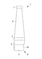
- FIG. 1A is a side view showing a turbine blade according to this embodiment
- FIG. 1B is a plan view showing the turbine blade according to this embodiment
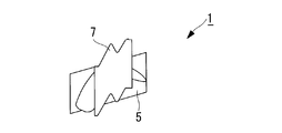
- FIG. 2 is a perspective view of the turbine rotor blade according to the present embodiment as viewed from the front side.
- the turbine rotor blade 1 includes, for example, a compression unit (not shown) that compresses combustion air, and injects and burns fuel into high-pressure air sent from the compression unit to perform high-temperature combustion.
- the present invention is applied to a gas turbine including a combustion section (not shown) that generates gas and a turbine section (not shown) that is located on the downstream side of the combustion section and is driven by the combustion gas exiting the combustion section. Is.
- the turbine rotor blade 1 is embedded in a blade groove 2a (see FIGS. 5 and 6) formed in a peripheral portion of a turbine disk 2 (see FIGS. 5 and 6).
- a Christmas tree-type blade root (base) 3 that holds (supports) the entire turbine rotor blade 1, a blade portion 4 that is exposed to high-temperature gas, a platform 5 that supports the blade portion 4, and a blade root 3 and the shanks 6 that connect the platform 5 and the tip (tip) of the blade 4 extend along the circumferential direction to prevent resonance of the turbine rotor blade 1 and leak loss (gas leakage) at the tip of the blade 4. ) Is provided.
- the turbine rotor blade 1 As shown in FIGS. 1A and 2, the turbine rotor blade 1 according to the present embodiment is arranged on the front edge side or the rear edge side of the blade root 3 in the longitudinal direction of the turbine rotor blade 1 (up and down in FIGS. 1A and 2).
- the cutout 8 is cut out uniformly (with a predetermined depth (for example, 5 mm)) from the tip (lower end) of the blade root 3 to the middle of the shank 6 along the direction.
- An end face 8a formed by the notch 8 and extending in the length direction (vertical direction in FIGS. 1A and 2) is formed at the peripheral edge of the turbine disk 2 when the turbine rotor blade 1 is assembled to the turbine disk 2. It is formed so as to be substantially parallel to the end face 2 b and extends partway through the shank 6.
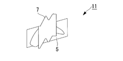
- the notch 8 of the turbine rotor blade 1 is a blade root 13 of a turbine blade (hereinafter referred to as “regular blade”) 11 that does not have the notch 8 as shown in FIGS. 3A, 3B and 4. 5, the end face 8a extending in the length direction formed by the notch 8 is embedded in the blade groove 2a of the turbine disk 2 up to a predetermined depth (for example, 5 mm).
- the turbine rotor blade 1 is formed so as to be set between the normal blade 11 and the normal blade 11 while being moved in a plane including the end surface 2 b forming the peripheral edge of the turbine disk 2.
- FIG. 5 and FIG. 6 indicate a turbine rotor including at least one turbine blade 1, a plurality of regular blades 11, and a turbine disk 2.
- the turbine rotor blade 1 configured as described above has an end face 8a extending in the length direction formed by the notch 8 when the blade root 3 is embedded in the blade groove 2a formed in the peripheral edge of the turbine disk 2 and assembled. Is moved in a plane including the end face 2b that forms the peripheral edge of the turbine disk 2 (that is, moved from the radially outer side toward the radially inner side), with respect to the blade groove 2a of the turbine disk 2. Can be set between the regular blade 11 and the regular blade 11 embedded to a depth of 5 mm (for example, 5 mm).
- the shroud 7 of the turbine rotor blade 1 and the regular blade 11 has a complicated plan view shape (regardless of the plan view shape), at least the blades embedded in the turbine disk 2 at the end (final) are used in this embodiment. Therefore, the blade root 3 of the turbine blade 1 and the blade root 13 of the regular blade 11 can be easily and quickly embedded (embedded) in the blade groove 2a of the turbine disk 2. Can do.
- the blade roots 3 and 13 are formed by the notches 8 of the turbine rotor blade 1 when the blade roots 3 and 13 are embedded and assembled in the blade groove 2a formed at the peripheral edge of the turbine disk 2.
- a turbine blade 1 capable of moving an end face 8a extending in a length direction in a plane including an end face 2b that forms a peripheral edge of the turbine disk 2 (that is, moving from a radially outer side toward a radially inner side). Therefore, the work process for assembling the turbine blade 1 and the regular blade 11 to the turbine disk 2 can be simplified, and the work time required for the assembling work can be shortened. Can be reduced.
- the present invention can be applied not only to a gas turbine but also to a steam turbine and other fluid rotary machines having a similar configuration.
- the present invention is not limited to the above-described embodiment, and can be appropriately modified and changed as necessary without departing from the technical idea of the present invention.
Landscapes
- Engineering & Computer Science (AREA)
- Mechanical Engineering (AREA)
- General Engineering & Computer Science (AREA)
- Turbine Rotor Nozzle Sealing (AREA)
Abstract
Priority Applications (5)
| Application Number | Priority Date | Filing Date | Title |
|---|---|---|---|
| EP09701788A EP2230385A4 (fr) | 2008-01-16 | 2009-01-08 | Pale de rotor de turbine |
| CN200980000565.7A CN101743380B (zh) | 2008-01-16 | 2009-01-08 | 涡轮动叶 |
| US12/673,494 US20110217175A1 (en) | 2008-01-16 | 2009-01-08 | Turbine rotor blade |
| JP2009550004A JP4939613B2 (ja) | 2008-01-16 | 2009-01-08 | タービン動翼 |
| ZA2010/01031A ZA201001031B (en) | 2008-01-16 | 2010-02-11 | Turbine rotor blade |
Applications Claiming Priority (2)
| Application Number | Priority Date | Filing Date | Title |
|---|---|---|---|
| JP2008-006895 | 2008-01-16 | ||
| JP2008006895 | 2008-01-16 |
Publications (1)
| Publication Number | Publication Date |
|---|---|
| WO2009090908A1 true WO2009090908A1 (fr) | 2009-07-23 |
Family
ID=40885299
Family Applications (1)
| Application Number | Title | Priority Date | Filing Date |
|---|---|---|---|
| PCT/JP2009/050160 Ceased WO2009090908A1 (fr) | 2008-01-16 | 2009-01-08 | Pale de rotor de turbine |
Country Status (7)
| Country | Link |
|---|---|
| US (1) | US20110217175A1 (fr) |
| EP (1) | EP2230385A4 (fr) |
| JP (1) | JP4939613B2 (fr) |
| CN (1) | CN101743380B (fr) |
| RU (1) | RU2010104753A (fr) |
| WO (1) | WO2009090908A1 (fr) |
| ZA (1) | ZA201001031B (fr) |
Cited By (1)
| Publication number | Priority date | Publication date | Assignee | Title |
|---|---|---|---|---|
| CN111058899A (zh) * | 2018-10-17 | 2020-04-24 | 普拉特 - 惠特尼加拿大公司 | 具有转子盘唇缘的转子组件 |
Families Citing this family (6)
| Publication number | Priority date | Publication date | Assignee | Title |
|---|---|---|---|---|
| EP2551460A1 (fr) * | 2011-07-29 | 2013-01-30 | Siemens Aktiengesellschaft | Groupe d'aubes |
| US10309232B2 (en) * | 2012-02-29 | 2019-06-04 | United Technologies Corporation | Gas turbine engine with stage dependent material selection for blades and disk |
| US10648354B2 (en) | 2016-12-02 | 2020-05-12 | Honeywell International Inc. | Turbine wheels, turbine engines including the same, and methods of forming turbine wheels with improved seal plate sealing |
| KR102790892B1 (ko) * | 2021-11-30 | 2025-04-02 | 두산에너빌리티 주식회사 | 터빈 블레이드, 이를 포함하는 터빈 및 가스터빈 |
| FR3143683A1 (fr) * | 2022-12-16 | 2024-06-21 | Safran Aircraft Engines | Systeme propulsif aeronautique |
| FR3143676A1 (fr) * | 2022-12-16 | 2024-06-21 | Safran Aircraft Engines | système PROPULSIF AERONAUTIQUE |
Citations (3)
| Publication number | Priority date | Publication date | Assignee | Title |
|---|---|---|---|---|
| JPS4837530A (fr) * | 1971-09-14 | 1973-06-02 | ||
| JPS5578103A (en) * | 1978-12-08 | 1980-06-12 | Hitachi Ltd | Method of implanting movable turbine blade |
| JPH1136806A (ja) * | 1997-07-11 | 1999-02-09 | Honda Motor Co Ltd | タービンブレード組付け装置 |
Family Cites Families (14)
| Publication number | Priority date | Publication date | Assignee | Title |
|---|---|---|---|---|
| US1720729A (en) * | 1928-03-29 | 1929-07-16 | Westinghouse Electric & Mfg Co | Blade fastening |
| US2974924A (en) * | 1956-12-05 | 1961-03-14 | Gen Electric | Turbine bucket retaining means and sealing assembly |
| US3501249A (en) * | 1968-06-24 | 1970-03-17 | Westinghouse Electric Corp | Side plates for turbine blades |
| US4533298A (en) * | 1982-12-02 | 1985-08-06 | Westinghouse Electric Corp. | Turbine blade with integral shroud |
| DE3528640A1 (de) * | 1985-06-28 | 1987-01-08 | Bbc Brown Boveri & Cie | Schaufelschloss fuer reiterfusschaufeln von turbomaschinen |
| US4702673A (en) * | 1985-10-18 | 1987-10-27 | General Electric Company | Method for assembly of tangential entry dovetailed bucket assemblies on a turbomachine bucket wheel |
| US5509784A (en) * | 1994-07-27 | 1996-04-23 | General Electric Co. | Turbine bucket and wheel assembly with integral bucket shroud |
| DE19520274A1 (de) * | 1995-06-02 | 1996-12-05 | Abb Management Ag | Vorrichtung und Verfahren zur Montage von Laufschaufeln |
| JP3682131B2 (ja) * | 1996-09-26 | 2005-08-10 | 株式会社東芝 | タービン動翼及びその組立方法 |
| US6061886A (en) * | 1997-07-11 | 2000-05-16 | Honda Giken Kogyo Kabushiki Kaisha | Turbine blade fitting apparatus and fitting method |
| US6030178A (en) * | 1998-09-14 | 2000-02-29 | General Electric Co. | Axial entry dovetail segment for securing a closure bucket to a turbine wheel and methods of installation |
| US7353588B2 (en) * | 2003-06-20 | 2008-04-08 | General Electric Company | Installation tool for assembling a rotor blade of a gas turbine engine fan assembly |
| JP4335771B2 (ja) * | 2004-09-16 | 2009-09-30 | 株式会社日立製作所 | タービン動翼及びタービン設備 |
| JP4869616B2 (ja) * | 2005-04-01 | 2012-02-08 | 株式会社日立製作所 | 蒸気タービン動翼と蒸気タービンロータ及びそれを用いた蒸気タービン並びにその発電プラント |
-
2009
- 2009-01-08 WO PCT/JP2009/050160 patent/WO2009090908A1/fr not_active Ceased
- 2009-01-08 US US12/673,494 patent/US20110217175A1/en not_active Abandoned
- 2009-01-08 CN CN200980000565.7A patent/CN101743380B/zh not_active Expired - Fee Related
- 2009-01-08 JP JP2009550004A patent/JP4939613B2/ja not_active Expired - Fee Related
- 2009-01-08 EP EP09701788A patent/EP2230385A4/fr not_active Withdrawn
- 2009-01-08 RU RU2010104753/06A patent/RU2010104753A/ru not_active Application Discontinuation
-
2010
- 2010-02-11 ZA ZA2010/01031A patent/ZA201001031B/en unknown
Patent Citations (3)
| Publication number | Priority date | Publication date | Assignee | Title |
|---|---|---|---|---|
| JPS4837530A (fr) * | 1971-09-14 | 1973-06-02 | ||
| JPS5578103A (en) * | 1978-12-08 | 1980-06-12 | Hitachi Ltd | Method of implanting movable turbine blade |
| JPH1136806A (ja) * | 1997-07-11 | 1999-02-09 | Honda Motor Co Ltd | タービンブレード組付け装置 |
Cited By (1)
| Publication number | Priority date | Publication date | Assignee | Title |
|---|---|---|---|---|
| CN111058899A (zh) * | 2018-10-17 | 2020-04-24 | 普拉特 - 惠特尼加拿大公司 | 具有转子盘唇缘的转子组件 |
Also Published As
| Publication number | Publication date |
|---|---|
| ZA201001031B (en) | 2011-08-31 |
| CN101743380B (zh) | 2014-01-01 |
| JP4939613B2 (ja) | 2012-05-30 |
| CN101743380A (zh) | 2010-06-16 |
| US20110217175A1 (en) | 2011-09-08 |
| JPWO2009090908A1 (ja) | 2011-05-26 |
| EP2230385A4 (fr) | 2011-03-16 |
| EP2230385A1 (fr) | 2010-09-22 |
| RU2010104753A (ru) | 2012-02-27 |
Similar Documents
| Publication | Publication Date | Title |
|---|---|---|
| JP4939613B2 (ja) | タービン動翼 | |
| US9328621B2 (en) | Rotor blade assembly tool for gas turbine engine | |
| JP4870954B2 (ja) | ガスタービンエンジンロータ組立体を組立てるための方法及び装置 | |
| US10001017B2 (en) | Turbomachine component with a stress relief cavity | |
| US10724404B2 (en) | Vane, gas turbine, ring segment, remodeling method for vane, and remodeling method for ring segment | |
| JP2008069781A (ja) | ブレードダブテール用のアンダカットフィレット半径 | |
| CN104822902B (zh) | 涡轮叶片装置 | |
| CA2615625C (fr) | Methodes et appareillage de fabrication d'un rotor | |
| US20130195633A1 (en) | Gas turbine rotary blade with tip insert | |
| JP2015517624A (ja) | 複数の構成部材から形成された面取りスクイーラ先端及び対流冷却孔を有するタービンブレード | |
| RU2012126745A (ru) | Способ лучевой сварки рабочего колеса с выполнением двух проходов паза, рабочее колесо и турбомашина с таким профилем сварки | |
| CN106523036A (zh) | 用于叶片盘应力减小(9e.04,2级)的叶片/盘燕尾后切口 | |
| CN104727860A (zh) | 锁定间隔组件 | |
| US10598024B2 (en) | Tandem rotor blades | |
| EP2372101A2 (fr) | Procédé de fabrication d'un élément d'étanchéité | |
| JP2012052523A (ja) | タービンブレード組立体 | |
| US10364687B2 (en) | Fan containing fan blades with a U-shaped slot having a decreased length planar section | |
| EP2998516B1 (fr) | Moteur a turbine a gaz | |
| US9624778B2 (en) | Rotor blade manufacture | |
| US10125613B2 (en) | Shrouded turbine blade with cut corner | |
| GB2510218B (en) | High-pressure turbine blades made of ceramic matrix composites | |
| JP2017223224A (ja) | ブレードの応力を低減するロックワイヤタブバックカット | |
| JP2010519455A (ja) | タービン・ホイール | |
| US20170218782A1 (en) | Modular turbine blade with separate platform support system |
Legal Events
| Date | Code | Title | Description |
|---|---|---|---|
| WWE | Wipo information: entry into national phase |
Ref document number: 200980000565.7 Country of ref document: CN |
|
| 121 | Ep: the epo has been informed by wipo that ep was designated in this application |
Ref document number: 09701788 Country of ref document: EP Kind code of ref document: A1 |
|
| WWE | Wipo information: entry into national phase |
Ref document number: 2009550004 Country of ref document: JP |
|
| WWE | Wipo information: entry into national phase |
Ref document number: 2009701788 Country of ref document: EP |
|
| WWE | Wipo information: entry into national phase |
Ref document number: 12673494 Country of ref document: US |
|
| NENP | Non-entry into the national phase |
Ref country code: DE |
|
| WWE | Wipo information: entry into national phase |
Ref document number: 2010104753 Country of ref document: RU |