EP0112418B1 - Revêtement antiréfléchissant pour écrans d'affichage - Google Patents
Revêtement antiréfléchissant pour écrans d'affichage Download PDFInfo
- Publication number
- EP0112418B1 EP0112418B1 EP82306867A EP82306867A EP0112418B1 EP 0112418 B1 EP0112418 B1 EP 0112418B1 EP 82306867 A EP82306867 A EP 82306867A EP 82306867 A EP82306867 A EP 82306867A EP 0112418 B1 EP0112418 B1 EP 0112418B1
- Authority
- EP
- European Patent Office
- Prior art keywords
- photopic
- visual display
- display unit
- reflectance
- coating
- Prior art date
- Legal status (The legal status is an assumption and is not a legal conclusion. Google has not performed a legal analysis and makes no representation as to the accuracy of the status listed.)
- Expired
Links
Images







Classifications
-
- H—ELECTRICITY
- H01—ELECTRIC ELEMENTS
- H01J—ELECTRIC DISCHARGE TUBES OR DISCHARGE LAMPS
- H01J29/00—Details of cathode-ray tubes or of electron-beam tubes of the types covered by group H01J31/00
- H01J29/86—Vessels; Containers; Vacuum locks
- H01J29/89—Optical or photographic arrangements structurally combined or co-operating with the vessel
- H01J29/896—Anti-reflection means, e.g. eliminating glare due to ambient light
-
- G—PHYSICS
- G02—OPTICS
- G02B—OPTICAL ELEMENTS, SYSTEMS OR APPARATUS
- G02B1/00—Optical elements characterised by the material of which they are made; Optical coatings for optical elements
- G02B1/10—Optical coatings produced by application to, or surface treatment of, optical elements
- G02B1/11—Anti-reflection coatings
- G02B1/113—Anti-reflection coatings using inorganic layer materials only
- G02B1/115—Multilayers
-
- H—ELECTRICITY
- H01—ELECTRIC ELEMENTS
- H01J—ELECTRIC DISCHARGE TUBES OR DISCHARGE LAMPS
- H01J2229/00—Details of cathode ray tubes or electron beam tubes
- H01J2229/89—Optical components associated with the vessel
- H01J2229/8913—Anti-reflection, anti-glare, viewing angle and contrast improving treatments or devices
- H01J2229/8918—Anti-reflection, anti-glare, viewing angle and contrast improving treatments or devices by using interference effects
Definitions
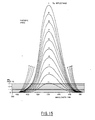
- the operating parameters can be modified so that an improved anti-reflection coating can be obtained.
- This improvement arises from the realization that it is not important to reduce the photometric reflectance evenly over the whole of the visible spectrum.
- the reflectance requirements at the less sensitive part of the visible spectrum can be relaxed allowing a corresponding decrease in the reflectance at the more sensitive part of the visible spectrum.
- the processing parameters can be more readily controlled to give a lower reflectance in that portion of the visible spectrum to which the eye is more sensitive.
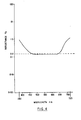
- Figure 5 illustrates the inverse-photopic nature of the photometric reflectance (curve 13).
- Figure 6 illustrates the CIE (Commission Internationale d I'Eclairage or International Commission on Illumination) 1931 Standard observer photopic response curve 15.
- Curve 13 in Figure 5 is derived by dividing a desired flat photopic response 14 by curve 15 of Figure 6. It will be appreciated that the photopic response of individuals will vary slightly from the standard curve. However this variation is of negligible effect. It will also be apparent that the photometric reflectance curve need not be exactly the inverse of the photopic response curve and that some variation is possible. The photopic reflectance need not be perfectly flat. In practical coatings the reflectance at the edges of the visible spectrum will not normally rise as steeply as shown in curve 13 of Figure 5 leading to a reduction in the photopic reflectance in these areas.
- CIE Commission Internationale d I'Eclairage or International Commission on Illumination
- the description has not considered the type of display device.
- the display device is a colour cathode ray tube or other device using three phosphors
- the photopic reflectance of the anti-reflection coating can be matched across the spectral band in the ratio of these luminances. Luminance contrast is more significant than colour contrast and this method maximizes the luminance contrast over the whole range of colours obtainable.
- a disadvantage is that a coating design depends on the actual colours used but this is not a major drawback.
- the luminance ratios for two whites are:-
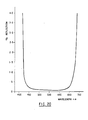
- Figures 25 to 30 are plots showing the photometric and photopic reflectances for three designs of anti-reflection coatings for two different light sources.
- the dotted curve 21 represents the photometric reflectance whilst the solid curve 22 represents the photopic reflectance.
- Figures 25 and 26 represent the reflectance due to a flat source and a cool white fluorescent source respectively for a relatively narrow bandwidth anti-reflection coating.
- Figures 27 and 28 are corresponding curves for a relatively wide bandwidth anti-reflection coating.
- the invention may be used in any visual display unit in which an image is viewed on or behind a reflecting surface, for example a head-up display.
Landscapes
- Physics & Mathematics (AREA)
- Inorganic Chemistry (AREA)
- General Physics & Mathematics (AREA)
- Optics & Photonics (AREA)
- Chemical & Material Sciences (AREA)
- Vessels, Lead-In Wires, Accessory Apparatuses For Cathode-Ray Tubes (AREA)
- Devices For Indicating Variable Information By Combining Individual Elements (AREA)
- Paints Or Removers (AREA)
- Laminated Bodies (AREA)
- Optical Elements Other Than Lenses (AREA)
- Application Of Or Painting With Fluid Materials (AREA)
- Overhead Projectors And Projection Screens (AREA)
- Surface Treatment Of Optical Elements (AREA)
Claims (9)
Priority Applications (8)
| Application Number | Priority Date | Filing Date | Title |
|---|---|---|---|
| DE8282306867T DE3275661D1 (en) | 1982-12-22 | 1982-12-22 | Improved anti-reflection coating for visual display screens |
| EP82306867A EP0112418B1 (fr) | 1982-12-22 | 1982-12-22 | Revêtement antiréfléchissant pour écrans d'affichage |
| AT82306867T ATE25880T1 (de) | 1982-12-22 | 1982-12-22 | Antireflektionsbeschichtung fuer bildschirme. |
| CA000438445A CA1249495A (fr) | 1982-12-22 | 1983-10-05 | Enduit antireflechissement pour ecrans de visualisation |
| JP58188587A JPS59121001A (ja) | 1982-12-22 | 1983-10-11 | 反射防止被覆を有する視覚的表示ユニツト |
| ES526468A ES8406792A1 (es) | 1982-12-22 | 1983-10-14 | Un dispositivo de presentacion visual que tiene una superficie frontal de vision y un revestimiento antireflectante |
| AU20252/83A AU561691B2 (en) | 1982-12-22 | 1983-10-18 | Anti-reflection coating for visual display screens |
| BR8307062A BR8307062A (pt) | 1982-12-22 | 1983-12-22 | Telas de exibicao visual e metodo de fabricacao de revestimento anti-refletor para as mesmas |
Applications Claiming Priority (1)
| Application Number | Priority Date | Filing Date | Title |
|---|---|---|---|
| EP82306867A EP0112418B1 (fr) | 1982-12-22 | 1982-12-22 | Revêtement antiréfléchissant pour écrans d'affichage |
Publications (2)
| Publication Number | Publication Date |
|---|---|
| EP0112418A1 EP0112418A1 (fr) | 1984-07-04 |
| EP0112418B1 true EP0112418B1 (fr) | 1987-03-11 |
Family
ID=8189869
Family Applications (1)
| Application Number | Title | Priority Date | Filing Date |
|---|---|---|---|
| EP82306867A Expired EP0112418B1 (fr) | 1982-12-22 | 1982-12-22 | Revêtement antiréfléchissant pour écrans d'affichage |
Country Status (8)
| Country | Link |
|---|---|
| EP (1) | EP0112418B1 (fr) |
| JP (1) | JPS59121001A (fr) |
| AT (1) | ATE25880T1 (fr) |
| AU (1) | AU561691B2 (fr) |
| BR (1) | BR8307062A (fr) |
| CA (1) | CA1249495A (fr) |
| DE (1) | DE3275661D1 (fr) |
| ES (1) | ES8406792A1 (fr) |
Families Citing this family (8)
| Publication number | Priority date | Publication date | Assignee | Title |
|---|---|---|---|---|
| US4779942A (en) * | 1985-12-09 | 1988-10-25 | United Technologies Corporation | NVG compatible red light |
| EP0596531B1 (fr) * | 1992-11-06 | 1997-07-09 | Kabushiki Kaisha Toshiba | Couche antiréfléchissante et dispositif d'affichage contenant cette couche |
| JP3569538B2 (ja) * | 1993-12-27 | 2004-09-22 | 松下電器産業株式会社 | 画像表示装置 |
| US6096371A (en) * | 1997-01-27 | 2000-08-01 | Haaland; Peter D. | Methods and apparatus for reducing reflection from optical substrates |
| US6172812B1 (en) * | 1997-01-27 | 2001-01-09 | Peter D. Haaland | Anti-reflection coatings and coated articles |
| DE102008041869A1 (de) * | 2008-09-08 | 2010-03-25 | Carl Zeiss Vision Gmbh | Brillenlinse mit farbneutraler Antireflexbeschichtung und Verfahren zu deren Herstellung |
| JP2012093689A (ja) | 2010-09-29 | 2012-05-17 | Nikon-Essilor Co Ltd | 光学部品およびその製造方法 |
| KR102928629B1 (ko) * | 2022-02-03 | 2026-02-23 | 삼성디스플레이 주식회사 | 윈도우 모듈 및 이를 포함하는 표시 장치 |
Family Cites Families (5)
| Publication number | Priority date | Publication date | Assignee | Title |
|---|---|---|---|---|
| US3421811A (en) * | 1967-10-31 | 1969-01-14 | Monsanto Co | Coated optical devices |
| US3576356A (en) * | 1969-01-14 | 1971-04-27 | Ibm | Antiglare coating for cathode-ray tube used with capacitive coupled voltage pen |
| JPS555413A (en) * | 1978-06-22 | 1980-01-16 | Yamaha Motor Co Ltd | Bearing lubricating construction for 2-cycle engine of vertical-crankshaft type |
| JPS56138701A (en) * | 1980-03-31 | 1981-10-29 | Minolta Camera Co Ltd | Antireflection film |
| JPS5714812A (en) * | 1980-06-30 | 1982-01-26 | Canon Inc | Optical system for copying machine |
-
1982
- 1982-12-22 EP EP82306867A patent/EP0112418B1/fr not_active Expired
- 1982-12-22 DE DE8282306867T patent/DE3275661D1/de not_active Expired
- 1982-12-22 AT AT82306867T patent/ATE25880T1/de not_active IP Right Cessation
-
1983
- 1983-10-05 CA CA000438445A patent/CA1249495A/fr not_active Expired
- 1983-10-11 JP JP58188587A patent/JPS59121001A/ja active Pending
- 1983-10-14 ES ES526468A patent/ES8406792A1/es not_active Expired
- 1983-10-18 AU AU20252/83A patent/AU561691B2/en not_active Ceased
- 1983-12-22 BR BR8307062A patent/BR8307062A/pt not_active IP Right Cessation
Also Published As
| Publication number | Publication date |
|---|---|
| AU2025283A (en) | 1984-06-28 |
| CA1249495A (fr) | 1989-01-31 |
| ES526468A0 (es) | 1984-07-16 |
| ATE25880T1 (de) | 1987-03-15 |
| BR8307062A (pt) | 1984-07-31 |
| AU561691B2 (en) | 1987-05-14 |
| ES8406792A1 (es) | 1984-07-16 |
| JPS59121001A (ja) | 1984-07-12 |
| EP0112418A1 (fr) | 1984-07-04 |
| DE3275661D1 (en) | 1987-04-16 |
Similar Documents
| Publication | Publication Date | Title |
|---|---|---|
| KR950000822B1 (ko) | 투영 텔레비젼 표시관 및 이를 구비한 투영 텔레비젼 장치 | |
| KR102312196B1 (ko) | 광발광 컬러 디스플레이 | |
| EP3032978B1 (fr) | Améliorations apportées et relatives à des visières | |
| US7025474B2 (en) | Dual mode display with a backlight filter for an unactivated light emitting diode (LED) | |
| WO2006071734A2 (fr) | Article de lunetterie et procede pour regarder des affichages a cristaux liquides | |
| EP0112418A1 (fr) | Revêtement antiréfléchissant pour écrans d'affichage | |
| US20100296028A1 (en) | Liquid crystal display panel and liquid crystal display device | |
| US7903206B2 (en) | Liquid crystal display device and producing method thereof with reflection and transmission display and a color filter having a color reproduction range | |
| US7517091B2 (en) | Color gamut improvement in presence of ambient light | |
| JPH09281317A (ja) | 波長選択性を有する光学部材 | |
| JPH07192660A (ja) | 画像表示装置 | |
| JP2003015118A (ja) | カラー液晶ディスプレイ | |
| JP2001028248A (ja) | コントラストが向上したcrt及びその製造方法 | |
| JPH0195450A (ja) | 陰極ルミネッセントけい光体の色度変更方法 | |
| EP1577706A1 (fr) | Ecran de projection et son procédé de fabrication | |
| JPH09507336A (ja) | 強い周囲光内で使用する陰極線管表示デバイス | |
| EP2837299A1 (fr) | Améliorations apportées et relatives à des visières | |
| EP1743213A1 (fr) | Dispositif lcd | |
| EP4394748A1 (fr) | Appareil de rendu de couleur de lumière blanche basé sur un panneau en vitrocéramique et procédé de réglage de couleur de lumière associé | |
| US6392337B1 (en) | Cathode ray tube | |
| JP2003131229A (ja) | 発光装置及び該発光装置を用いた表示装置 | |
| JPH1184122A (ja) | カラーフィルタ | |
| CN100432765C (zh) | 液晶显示装置以及使用该装置的显示机器 | |
| WO2024023502A1 (fr) | Revêtement pour surfaces optiques | |
| TW202201365A (zh) | 顯示裝置 |
Legal Events
| Date | Code | Title | Description |
|---|---|---|---|
| PUAI | Public reference made under article 153(3) epc to a published international application that has entered the european phase |
Free format text: ORIGINAL CODE: 0009012 |
|
| AK | Designated contracting states |
Designated state(s): AT BE CH DE FR GB IT LI NL SE |
|
| 17P | Request for examination filed |
Effective date: 19841029 |
|
| 17Q | First examination report despatched |
Effective date: 19860129 |
|
| GRAA | (expected) grant |
Free format text: ORIGINAL CODE: 0009210 |
|
| AK | Designated contracting states |
Kind code of ref document: B1 Designated state(s): AT BE CH DE FR GB IT LI NL SE |
|
| REF | Corresponds to: |
Ref document number: 25880 Country of ref document: AT Date of ref document: 19870315 Kind code of ref document: T |
|
| REF | Corresponds to: |
Ref document number: 3275661 Country of ref document: DE Date of ref document: 19870416 |
|
| ET | Fr: translation filed | ||
| ITF | It: translation for a ep patent filed | ||
| PLBE | No opposition filed within time limit |
Free format text: ORIGINAL CODE: 0009261 |
|
| STAA | Information on the status of an ep patent application or granted ep patent |
Free format text: STATUS: NO OPPOSITION FILED WITHIN TIME LIMIT |
|
| 26N | No opposition filed | ||
| ITTA | It: last paid annual fee | ||
| PGFP | Annual fee paid to national office [announced via postgrant information from national office to epo] |
Ref country code: CH Payment date: 19940322 Year of fee payment: 12 |
|
| PGFP | Annual fee paid to national office [announced via postgrant information from national office to epo] |
Ref country code: FR Payment date: 19941201 Year of fee payment: 13 |
|
| PGFP | Annual fee paid to national office [announced via postgrant information from national office to epo] |
Ref country code: DE Payment date: 19941220 Year of fee payment: 13 |
|
| PG25 | Lapsed in a contracting state [announced via postgrant information from national office to epo] |
Ref country code: LI Effective date: 19941231 Ref country code: CH Effective date: 19941231 |
|
| EAL | Se: european patent in force in sweden |
Ref document number: 82306867.1 |
|
| REG | Reference to a national code |
Ref country code: CH Ref legal event code: PL |
|
| PGFP | Annual fee paid to national office [announced via postgrant information from national office to epo] |
Ref country code: BE Payment date: 19951023 Year of fee payment: 14 |
|
| PGFP | Annual fee paid to national office [announced via postgrant information from national office to epo] |
Ref country code: AT Payment date: 19951122 Year of fee payment: 14 |
|
| PGFP | Annual fee paid to national office [announced via postgrant information from national office to epo] |
Ref country code: GB Payment date: 19951127 Year of fee payment: 14 |
|
| PGFP | Annual fee paid to national office [announced via postgrant information from national office to epo] |
Ref country code: SE Payment date: 19951204 Year of fee payment: 14 |
|
| PGFP | Annual fee paid to national office [announced via postgrant information from national office to epo] |
Ref country code: NL Payment date: 19951230 Year of fee payment: 14 |
|
| PG25 | Lapsed in a contracting state [announced via postgrant information from national office to epo] |
Ref country code: FR Effective date: 19960830 |
|
| PG25 | Lapsed in a contracting state [announced via postgrant information from national office to epo] |
Ref country code: DE Effective date: 19960903 |
|
| REG | Reference to a national code |
Ref country code: FR Ref legal event code: ST |
|
| PG25 | Lapsed in a contracting state [announced via postgrant information from national office to epo] |
Ref country code: GB Effective date: 19961222 Ref country code: AT Effective date: 19961222 |
|
| PG25 | Lapsed in a contracting state [announced via postgrant information from national office to epo] |
Ref country code: SE Effective date: 19961223 |
|
| PG25 | Lapsed in a contracting state [announced via postgrant information from national office to epo] |
Ref country code: BE Effective date: 19961231 |
|
| BERE | Be: lapsed |
Owner name: INTERNATIONAL BUSINESS MACHINES CORP. Effective date: 19961231 |
|
| PG25 | Lapsed in a contracting state [announced via postgrant information from national office to epo] |
Ref country code: NL Effective date: 19970701 |
|
| GBPC | Gb: european patent ceased through non-payment of renewal fee |
Effective date: 19961222 |
|
| NLV4 | Nl: lapsed or anulled due to non-payment of the annual fee |
Effective date: 19970701 |
|
| EUG | Se: european patent has lapsed |
Ref document number: 82306867.1 |