EP0112907B2 - Mittel zum periodischen regenerieren einer kältepumpe - Google Patents
Mittel zum periodischen regenerieren einer kältepumpe Download PDFInfo
- Publication number
- EP0112907B2 EP0112907B2 EP83902402A EP83902402A EP0112907B2 EP 0112907 B2 EP0112907 B2 EP 0112907B2 EP 83902402 A EP83902402 A EP 83902402A EP 83902402 A EP83902402 A EP 83902402A EP 0112907 B2 EP0112907 B2 EP 0112907B2
- Authority
- EP
- European Patent Office
- Prior art keywords
- cryopanel
- cryopump
- chamber
- primary
- heat sink
- Prior art date
- Legal status (The legal status is an assumption and is not a legal conclusion. Google has not performed a legal analysis and makes no representation as to the accuracy of the status listed.)
- Expired
Links
- 238000003795 desorption Methods 0.000 title description 2
- 230000000737 periodic effect Effects 0.000 title description 2
- 238000009835 boiling Methods 0.000 claims abstract description 23
- 238000010438 heat treatment Methods 0.000 claims description 19
- 239000000835 fiber Substances 0.000 claims description 5
- 229910000986 non-evaporable getter Inorganic materials 0.000 claims description 4
- 230000003287 optical effect Effects 0.000 claims description 3
- 238000000859 sublimation Methods 0.000 claims description 2
- 230000008022 sublimation Effects 0.000 claims description 2
- 230000000694 effects Effects 0.000 abstract description 2
- 239000007789 gas Substances 0.000 description 42
- 238000000034 method Methods 0.000 description 19
- 238000005086 pumping Methods 0.000 description 14
- UFHFLCQGNIYNRP-UHFFFAOYSA-N Hydrogen Chemical compound [H][H] UFHFLCQGNIYNRP-UHFFFAOYSA-N 0.000 description 13
- 239000001257 hydrogen Substances 0.000 description 10
- 229910052739 hydrogen Inorganic materials 0.000 description 10
- 230000005855 radiation Effects 0.000 description 9
- OKTJSMMVPCPJKN-UHFFFAOYSA-N Carbon Chemical compound [C] OKTJSMMVPCPJKN-UHFFFAOYSA-N 0.000 description 8
- 239000003463 adsorbent Substances 0.000 description 8
- 230000008929 regeneration Effects 0.000 description 5
- 238000011069 regeneration method Methods 0.000 description 5
- 239000002594 sorbent Substances 0.000 description 5
- XLYOFNOQVPJJNP-UHFFFAOYSA-N water Chemical compound O XLYOFNOQVPJJNP-UHFFFAOYSA-N 0.000 description 5
- XKRFYHLGVUSROY-UHFFFAOYSA-N Argon Chemical compound [Ar] XKRFYHLGVUSROY-UHFFFAOYSA-N 0.000 description 4
- IJGRMHOSHXDMSA-UHFFFAOYSA-N Atomic nitrogen Chemical compound N#N IJGRMHOSHXDMSA-UHFFFAOYSA-N 0.000 description 4
- 229910052782 aluminium Inorganic materials 0.000 description 3
- XAGFODPZIPBFFR-UHFFFAOYSA-N aluminium Chemical compound [Al] XAGFODPZIPBFFR-UHFFFAOYSA-N 0.000 description 3
- 230000005294 ferromagnetic effect Effects 0.000 description 3
- 239000011521 glass Substances 0.000 description 3
- 238000004519 manufacturing process Methods 0.000 description 3
- 229920006395 saturated elastomer Polymers 0.000 description 3
- CURLTUGMZLYLDI-UHFFFAOYSA-N Carbon dioxide Chemical compound O=C=O CURLTUGMZLYLDI-UHFFFAOYSA-N 0.000 description 2
- 229910052786 argon Inorganic materials 0.000 description 2
- 239000003610 charcoal Substances 0.000 description 2
- 238000006243 chemical reaction Methods 0.000 description 2
- 238000004891 communication Methods 0.000 description 2
- 239000001307 helium Substances 0.000 description 2
- 229910052734 helium Inorganic materials 0.000 description 2
- SWQJXJOGLNCZEY-UHFFFAOYSA-N helium atom Chemical compound [He] SWQJXJOGLNCZEY-UHFFFAOYSA-N 0.000 description 2
- 229910052754 neon Inorganic materials 0.000 description 2
- GKAOGPIIYCISHV-UHFFFAOYSA-N neon atom Chemical compound [Ne] GKAOGPIIYCISHV-UHFFFAOYSA-N 0.000 description 2
- 229910052757 nitrogen Inorganic materials 0.000 description 2
- RYGMFSIKBFXOCR-UHFFFAOYSA-N Copper Chemical compound [Cu] RYGMFSIKBFXOCR-UHFFFAOYSA-N 0.000 description 1
- -1 as for example Substances 0.000 description 1
- 239000006227 byproduct Substances 0.000 description 1
- 229910002092 carbon dioxide Inorganic materials 0.000 description 1
- 239000001569 carbon dioxide Substances 0.000 description 1
- 229910052802 copper Inorganic materials 0.000 description 1
- 239000010949 copper Substances 0.000 description 1
- 238000000151 deposition Methods 0.000 description 1
- 230000008021 deposition Effects 0.000 description 1
- 230000008014 freezing Effects 0.000 description 1
- 238000007710 freezing Methods 0.000 description 1
- 229910052736 halogen Inorganic materials 0.000 description 1
- 150000002367 halogens Chemical class 0.000 description 1
- 150000002431 hydrogen Chemical class 0.000 description 1
- 230000000415 inactivating effect Effects 0.000 description 1
- 239000000463 material Substances 0.000 description 1
- 230000013011 mating Effects 0.000 description 1
- 229910052751 metal Inorganic materials 0.000 description 1
- 239000002184 metal Substances 0.000 description 1
- 239000002808 molecular sieve Substances 0.000 description 1
- 239000004065 semiconductor Substances 0.000 description 1
- URGAHOPLAPQHLN-UHFFFAOYSA-N sodium aluminosilicate Chemical compound [Na+].[Al+3].[O-][Si]([O-])=O.[O-][Si]([O-])=O URGAHOPLAPQHLN-UHFFFAOYSA-N 0.000 description 1
- 238000004544 sputter deposition Methods 0.000 description 1
- WFKWXMTUELFFGS-UHFFFAOYSA-N tungsten Chemical compound [W] WFKWXMTUELFFGS-UHFFFAOYSA-N 0.000 description 1
- 229910052721 tungsten Inorganic materials 0.000 description 1
- 239000010937 tungsten Substances 0.000 description 1
- 238000010792 warming Methods 0.000 description 1
Images



Classifications
-
- F—MECHANICAL ENGINEERING; LIGHTING; HEATING; WEAPONS; BLASTING
- F04—POSITIVE - DISPLACEMENT MACHINES FOR LIQUIDS; PUMPS FOR LIQUIDS OR ELASTIC FLUIDS
- F04B—POSITIVE-DISPLACEMENT MACHINES FOR LIQUIDS; PUMPS
- F04B37/00—Pumps having pertinent characteristics not provided for in, or of interest apart from, groups F04B25/00 - F04B35/00
- F04B37/02—Pumps having pertinent characteristics not provided for in, or of interest apart from, groups F04B25/00 - F04B35/00 for evacuating by absorption or adsorption
-
- F—MECHANICAL ENGINEERING; LIGHTING; HEATING; WEAPONS; BLASTING
- F04—POSITIVE - DISPLACEMENT MACHINES FOR LIQUIDS; PUMPS FOR LIQUIDS OR ELASTIC FLUIDS
- F04B—POSITIVE-DISPLACEMENT MACHINES FOR LIQUIDS; PUMPS
- F04B37/00—Pumps having pertinent characteristics not provided for in, or of interest apart from, groups F04B25/00 - F04B35/00
- F04B37/06—Pumps having pertinent characteristics not provided for in, or of interest apart from, groups F04B25/00 - F04B35/00 for evacuating by thermal means
- F04B37/08—Pumps having pertinent characteristics not provided for in, or of interest apart from, groups F04B25/00 - F04B35/00 for evacuating by thermal means by condensing or freezing, e.g. cryogenic pumps
-
- Y—GENERAL TAGGING OF NEW TECHNOLOGICAL DEVELOPMENTS; GENERAL TAGGING OF CROSS-SECTIONAL TECHNOLOGIES SPANNING OVER SEVERAL SECTIONS OF THE IPC; TECHNICAL SUBJECTS COVERED BY FORMER USPC CROSS-REFERENCE ART COLLECTIONS [XRACs] AND DIGESTS
- Y10—TECHNICAL SUBJECTS COVERED BY FORMER USPC
- Y10S—TECHNICAL SUBJECTS COVERED BY FORMER USPC CROSS-REFERENCE ART COLLECTIONS [XRACs] AND DIGESTS
- Y10S417/00—Pumps
- Y10S417/901—Cryogenic pumps
Definitions
- This invention relates to the production of high vacuum by cryogenic freezing of gases and more particularly to means for selectively removing excess gases which have been adsorbed in a cryopump.
- cryopumping or “cryogenic pumping” is the technique of producing low pressures within an enclosed vessel by condensing or adsorbing the gases within the vessel on surfaces cooled to cryogenic temperatures. Cryopumping generally takes place in two or more stages. Gases called Type I gases including water vapor, carbon dioxide and halogens among others with moderately low boiling points are frozen on first stage cryopanels cooled to temperatures of approximately 100°K.
- Type II gases including nitrogen and argon among others are frozen onto second stage cryopanels cooled to approximately 20°K.
- the lowest boiling point gases including hydrogen, helium and neon called Type III gases, are cryogenically adsorbed on adsorbents such as molecular sieve or activated charcoal which are attached to surfaces in the form of a box or trap and cooled to temperatures below 20°K.
- adsorbents such as molecular sieve or activated charcoal which are attached to surfaces in the form of a box or trap and cooled to temperatures below 20°K.
- the box or trap is often referred to as the primary pumping surface or primary cryopanel.
- Cryopumps have found particular usage by being attached to chambers in which operations are to be performed requiring very low pressures. Examples of such operations include the deposition of metallic and non-metallic films having specific electrical or optical properties. These films are used in the semi-conductor industry in the manufacture of integrated circuits and in the optical industry and in the manufacture of lenses, filters and mirrors. In many such processes, hydrogen is liberated as a by-product of water- metal reactions or by ionization of water vapor.
- the capacity of typical cryopumps for Type III (cryosorbed) gases such as hydrogen is generally much less than for the Type I or Type 11 gases, which are frozen. Consequenty, the adsorbent in the pump becomes saturated after a relatively few number of hours of operation.
- the adsorbent In order to renew the adsorbent capacity, the adsorbent must be warmed and the cryosorbed gases devolved. This regeneration is normally accomplished by inactivating the cryopump and warming it. The gases evolved as the pump warms are removed by secondary pumping means.
- GB-A-2,065,782 describes a cryopump comprising a chamber, a primary cryopanel (second pumping stage) associated with a low temperature heat sink having means for adsorbing a first low boiling point gas in said chamber, a secondary cryopanel (first pumping stage) associated with a higher temperature heat sink having means for condensing a higher boiling point gas in said chamber and an electrical heating element for selectively heating the primary cryopanel to cause said first gas to become desorbed from said primary cryopanel, no substantial heating of the secondary cryopanel occurring.
- cryopumps are known to release undiluted hydrogen gas during the regeneration process, the use of electrical elements within the cryopump chamber are considered undesirable in as far as they present the risk of a spark which could ignite the hydrogen gas.
- This invention is particularly directed to avoiding this problem.
- the present invention provides a cryopump comprising a chamber, a primary cryopanel associated with a low temperature heat sink having means for adsorbing a first low boiling point gas in said chamber, a second cryopanel associated with a higher temperature heat sink having means for condensing a higher boiling point gas in said chamber, and means for selectively heating the primary cryopanel to raise the temperature of the primary cryopanel above that which is necessary to cause said first gas to become desorbed from said cryopanel such that there is no substantial heating of the secondary cryopanel characterized in that said heating means comprises a heat conductive rod for transmitting heat energy from a heat source external to the cryopump chamber to the primary cryopanel, said rod being movable selectively into and out of engagement with said low temperature heat sink.
- the present invention also provides a cryopump comprising a chamber, a primary cryopanel associated with a low temperature heat sink having means for adsorbing a first low boiling point gas in said chamber, a secondary cryopanel associated with a higher temperature heat sink having means for condensing a higher boiling point gas in said chamber and means for selectively heating the primary cryopanel to raise the temperature of the primary cryopanel above that which is necessary to cause said first gas to become desorbed from said cryopanel such that there is no substantial heating of the secondary cryopanel characterized in that said heating means comprises means for transmitting heat energy from a high temperature light energy source external to the cryopump chamber to the primary cryopanel.
- the selective desorption process does not substantially add heat to the secondary cryopanel, it does not cause sublimation of the higher boiling point gas or gases from that secondary cryopanel.
- the desorbed gas as for example, hydrogen is removed from the system by a secondary pumping means which may be, for example, a non-evaporable getter pump which may be located off-line in order that it too may be purged of excess gas while the cryopump and the process are in operation thereby not causing any down time.
- a secondary pumping means which may be, for example, a non-evaporable getter pump which may be located off-line in order that it too may be purged of excess gas while the cryopump and the process are in operation thereby not causing any down time.
- the heat energy transmitting means may be a lens means or a fibre optic means.
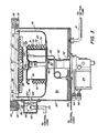
- FIG. 1 there will be seen a cryopump 10 connected directly to a work processing chamber 12.
- Tubulation 14 leads to a roughing pump (not shown).
- a non-evaporable getter pump 16 or other equivalent pumping means communicates with the cryopump 10 by way of the tubulation 14.
- a shutoff valve 18 is interposed between the getter pump and the tubulation 14 while shutoff valves 20 and 22 are located between the getter pump 16 and the cryopump 10 and the getter pump and the roughing pump respectively.
- the cryopump is driven by a motor 24.
- a control logic 26 is connected to a temperature sensor not seen in Figure 1 but located within the cryopump and to a housing 28 of a heat conducting mechanism movable within the cryopump 10.
- the pump includes a main chamber 30 formed in part by a wall which is mounted to the wall 32 of the work processing chamber 12 by means of a circular flange 33 and is secured to a mating flange 34 by a plurality of bolts 36 (only one of which is shown).
- a circular opening 38 in the flange 34 permits communication between the process chamber 12 and the chamber 30 of the cryopump 10.
- a two-stage cold finger 40 of a refrigerator protrudes into the chamber 30 through an opening 42.
- the refrigerator is a Gifford-McMahon type.
- other types of refrigerators may be used if it be so desired.
- a two-stage displacer in the cold finger 40 is driven by the motor 24. With each cycle, helium gas is introduced into the cold finger 40 under pressure through a line 44. It is expanded and thus cooled and then exhausted through a line 46.
- Such a refrigerator is disclosed in U.S. Patent No. 3,218,815 to Chellis et al.
- a first stage heat sink or heat station 48 is mounted at the cold end of the first stage 50 of the refrigerator cold finger 40.
- a heat sink 60 is mounted on the cold end of the second stage 62 of the refrigerator cold finger.
- a suitable temperature sensor element 64 is mounted adjacent to the heat sink 60.
- a line 66 connects it to the control logic 26 ( Figure 1) outside the cryopump.
- the second stage array pumping surface or cryopanel indicated generally as 67 is a circular array mounted on the heat sink 60.
- This panel comprises a disc 68 and a set of circularly arranged chevrons 70 arranged in a vertical array and mounted to the disc 68.
- a trap 71 comprising an outer cylindrical surface 72 holds a low temperature sorbent such as activated charcoal 74. Access is gained to this sorbent by low boiling point gases through the chevrons 70 (see Figure 2).
- Surface 70 and the adsorbent 74 can be loosely termed the primary low temperature cryopanel.
- a cup-shaped radiation shield 76 is mounted to the first stage, high temperature heat sink 48.
- the second stage 62 of the cold finger 40 extends through an opening 78 in the radiation shield.
- the shield 76 which surrounds the primary cryopanel 67 to the rear and sides, minimizes heating of the primary cryopanel by radiation.
- a frontal cryopanel 80 serves as both a radiation shield for the primary cryopanel 67 and as a cryopumping surface for higher boiling temperature Type I gases such as water vapor.
- This panel comprises a circular array of concentric louvres and chevrons 82 joined by spoke-like rods 84 fixed in the shield 76.
- the configuration of this array need not be confined to a circular concentric components. However, it should be an array of baffles so arranged as to act as a radiant heat shield and a higher temperature cryopumping panel while providing a path for lower boiling temperature gases to the primary cryopanel 67.
- the shield 76 must be sufficiently enlarged to permit unobstructed flow of gases to the primary cryopanel within the heat shield.
- the low boiling point gas desorbing means includes the housing 28 within which there is a high conductivity (preferably copper) heat bar 90 mounted for sliding movement through the wall 30 of the cryopump.
- a spring 92 is compressed between a solenoid 94 and the head 96 of a ferromagnetic portion 97 threaded onto the heat bar 90.
- the bar passes through a bellows seal 95 and the radiation shield 76, being guided by a knife edge low conductivity guide 98. In like manner, it passes through the primary pumping surface 67. Its innermost end 100 is engageable with a flatheaded boss 102 on the second stage 62 of the cold finger 40 in thermal communication with the heat sink 60.
- the solenoid 94 surrounds the ferromagnetic portion of the heat bar 90 to the right of the head 96 as viewed in Figure 2.
- the solenoid is actuated, in a manner to be explained in more detail hereinafter, the ferromagnetic portion of the heat bar 90 is drawn to the right, moving the bar with it through the wall 30 of the cryopump and the heat shield 76, until the flat end 100 of the bar engages the flat face 101 of the boss 102.
- This permits heat from outside the cryopump wall 30 to be conducted through the bar directly to the second stage 62 of the refrigerator without significantly raising the temperature of the shield 76 thus without causing an appreciable temperature rise in the high temperature stage of the cryopump.
- Heating the primary cryopanel to about 40°K causes the hydrogen or other gas on the primary pumping surface to be desorbed, the gas or gases having previously been adsorbed at from 10 to 25°K.
- the temperature sensor 64 connected to the control logic 26 is in position to detect temperature changes within the cryopump and thereby to deactivate the solenoid before the additional thermal load due to gas conduction caused by the devolved gas exceeds the capacity of the pump.
- valve 18 leading to the getter pump 16 is initially closed while valves 20 and 22 are opened to permit the roughing pump to begin to evacuate the cryopump and the processing chamber 12 which are initially at atmospheric pressure.
- valves 20 and 22 are closed and the roughing pump turned off.
- the cryopump motor 24 is then turned on.
- the first stage of the refrigerator cools the secondary pumping surfaces down to approximately 70°K causing the relatively high boiling point Type I gases, such as water vapor, to become condensed on the pumping surfaces of the secondary cryopanel.
- the second stage continues to be cooled down to approximately 10 to 25°K causing Type II gases such as nitrogen and argon to be deposited on the cold stage array 67 and causing Type III gases such as hydrogen and neon to begin to become adsorbed in the activated charcoal sorbent.
- Type II gases such as nitrogen and argon
- Type III gases such as hydrogen and neon to begin to become adsorbed in the activated charcoal sorbent.
- operation may commence in the chamber.
- the process involves aluminum sputtering where aluminum is evaporated onto a workpiece. The presence of water vapor produces hydrogen gas by reaction with the aluminum. The hydrogen gas thus being produced along with other gases originally in the pump 10 and the chamber 12 begin to become adsorbed by the activated charcoal. Because the hydrogen is being produced continuously, and because the total capacity is limited by the amount of charcoal or other adsorbents present, subsequently the sorbent becomes saturated and the pressure within the process chamber begins to increase making it impractical to continue.
- the solenoid 94 is actuated to move the heater bar 90 into engagement with the boss 102 on the heat sink 62.
- the cryopump need not be turned off allowing the first stage, i.e., the secondary pumping surfaces 80, to be continuously cooled to about 70°K.
- the heater bar remains in contact with the boss 102 until the second stage or primary pumping surfaces become heated to approximately 40°K which causes the hydrogen to be desorbed from the adsorbent.
- valves 18, 20 and 22 are closed. Valves 18 and 20 are then opened, either by automatic control means or manually if it be so desired.
- the getter pump 16 is then allowed to pump the hydrogen which has been desorbed from the adsorbent 74.
- a pressure sensor will signal when the pressure within the pump 10 has fallen to a predetermined level indicating that the hydrogen has been removed. During this time, the process chamber may be recycled by the operator.
- the heater bar 90 is then withdrawn from the boss 102 by the opening 92, by the solenoid 94 being turned off either by the control logic 26 or manually if so desired.
- Valve 20 leading to the getter pump is closed.
- the second stage of the refrigerator then proceeds to cool down below 40°K toward 10°K causing whatever remaining gases there are in the pump to be adsorbed on the charcoal.
- the entire system reaches a pressure where it again becomes suitable to reinstitute the work process within the chamber.
- the getter pump Since the getter pump is only employed intermittently and is closed off from the system, it can be regenerated at will. Since this is done "off-line", it does not interfere with the process cycle.
- the periodic regeneration of the cryopump assures that the time for the sorbent to become saturated and require a total regeneration is substantially extended.
- Both means transmit energy from a high temperature energy source.
- the radiation source is light energy.
- Bodies radiate energy in accordance with their temperature. As a body gets warmer, it not only radiates more energy, but proportionally more and more energy at shorter wavelengths. Since there exists materials which transmit energy over specific ranges of wave lengths the combining of an energy source and transmitting source follows.
- a high temperature lamp 110 mounted within an enclosure 112 which is bolted or otherwise secured to the outside of the chamber 30 of the cryopump.
- the lamp 110 is connected by suitable wiring 114 to the control logic.
- Line of sight view from the lamp to the flat face 101 of the boss 102 on the second stage 62 of the cold finger 40 is provided.
- the line of sight includes an opening 116 in the shield 76 and a second aligned opening 118 in the cup-shaped radiation shield 76.
- An opening 120 in the wall of the chamber 30 of the pump is sealed with a glass plug 122.
- a collimating lens 124 is located between the lamp and the plug 122.
- the high temperature lamp 110 When the high temperature lamp 110 is off, it radiates no energy to the surface 101 on the boss 102. However, when the lamp is turned on, it radiates energy at a wavelength which can be transmitted through the collimating lens and glass plug 122.
- glass is essentially transparent to .4-2 um wavelength radiation but opaque to other frequencies.
- a black body at 300°K emits less than 1.3 times 10- 5 percent of its energy at this range. Whereas at 3000°K (the temperature of a tungsten filament), it emits 73.6 percent of its energy in this range.
- the surface or face 101 of the boss 102 is appropriately darkened to absorb the maximum amount of heat. Thus, through the use of radiant energy under the control of the control logic, heat may be selectively transferred to the heat sink 60 of the blank 62 of the cold finger 40.
- FIG. 4 Another form of transmitting means is shown in Figure 4 and includes a fibre optic bundle 1120 supported by means 1122 in close proximity to the face 101 of the boss 102 on the heat sink 60.
- the fibre optic bundle passes through an opening 124 in the panel 67 as well as an opening 126 in the radiation shield 76. It is firmly clamped by means 128 on the wall of the chamber 30 of the cryopump and extends outwardly thereof to any convenient point where it receives its energy from an appropriate light source which is connected to the control logic.
- the light source in this instance is illustrated as a light-emitting diode 130.
- the method of operating the cryopump for selective desorbtion is the same with fibre optic bundle mechanism as with the lamp and conductive rods hereinabove described.
Landscapes
- Engineering & Computer Science (AREA)
- Mechanical Engineering (AREA)
- General Engineering & Computer Science (AREA)
- Compressors, Vaccum Pumps And Other Relevant Systems (AREA)
Claims (7)
Priority Applications (1)
| Application Number | Priority Date | Filing Date | Title |
|---|---|---|---|
| AT83902402T ATE23386T1 (de) | 1982-07-06 | 1983-07-01 | Mittel zum periodischen regenerieren einer kaeltepumpe. |
Applications Claiming Priority (2)
| Application Number | Priority Date | Filing Date | Title |
|---|---|---|---|
| US06/395,120 US4438632A (en) | 1982-07-06 | 1982-07-06 | Means for periodic desorption of a cryopump |
| US395120 | 1999-09-14 |
Publications (3)
| Publication Number | Publication Date |
|---|---|
| EP0112907A1 EP0112907A1 (de) | 1984-07-11 |
| EP0112907B1 EP0112907B1 (de) | 1986-11-05 |
| EP0112907B2 true EP0112907B2 (de) | 1990-06-27 |
Family
ID=23561781
Family Applications (1)
| Application Number | Title | Priority Date | Filing Date |
|---|---|---|---|
| EP83902402A Expired EP0112907B2 (de) | 1982-07-06 | 1983-07-01 | Mittel zum periodischen regenerieren einer kältepumpe |
Country Status (4)
| Country | Link |
|---|---|
| US (1) | US4438632A (de) |
| EP (1) | EP0112907B2 (de) |
| DE (1) | DE3367434D1 (de) |
| WO (1) | WO1984000404A1 (de) |
Families Citing this family (45)
| Publication number | Priority date | Publication date | Assignee | Title |
|---|---|---|---|---|
| US4446702A (en) * | 1983-02-14 | 1984-05-08 | Helix Technology Corporation | Multiport cryopump |
| GB8400349D0 (en) * | 1984-01-07 | 1984-02-08 | Boc Group Plc | Cryogenic pumps |
| US4910965A (en) * | 1984-06-29 | 1990-03-27 | Helix Technology Corporation | Means for periodic desorption of a cryopump |
| FR2572794B1 (fr) * | 1984-11-06 | 1987-06-12 | Commissariat Energie Atomique | Procede pour augmenter la capacite d'absorption d'une pompe de cryopompage et pompe de cryopompage associee |
| US4719938A (en) * | 1985-01-22 | 1988-01-19 | Helix Technology Corporation | Self-cleaning valve and cryopump utilizing the same |
| US4718240A (en) * | 1985-03-01 | 1988-01-12 | Helix Technology Corporation | Cryopump regeneration method and apparatus |
| JPS62502276A (ja) * | 1985-03-01 | 1987-09-03 | ヘリックス・テクノロジ−・コ−ポレ−ション | 低温ポンプの再生方法および装置 |
| DE3512614A1 (de) * | 1985-04-06 | 1986-10-16 | Leybold-Heraeus GmbH, 5000 Köln | Verfahren zur inbetriebnahme und/oder regenerierung einer kryopumpe und fuer dieses verfahren geeignete kryopumpe |
| US4679401A (en) * | 1985-07-03 | 1987-07-14 | Helix Technology Corporation | Temperature control of cryogenic systems |
| US4655046A (en) * | 1985-07-19 | 1987-04-07 | Helix Technology Corporation | Cryopump with exhaust filter |
| DE3690477T1 (de) * | 1985-09-24 | 1987-10-08 | ||
| FR2599789B1 (fr) * | 1986-06-04 | 1990-03-23 | Air Liquide | Procede de regeneration d'un etage de cryopompe ou de cryocondenseur et cryopompe pour sa mise en oeuvre |
| DE3680335D1 (de) * | 1986-06-23 | 1991-08-22 | Leybold Ag | Kryopumpe und verfahren zum betrieb dieser kryopumpe. |
| US4763483A (en) * | 1986-07-17 | 1988-08-16 | Helix Technology Corporation | Cryopump and method of starting the cryopump |
| US4724677A (en) * | 1986-10-09 | 1988-02-16 | Foster Christopher A | Continuous cryopump with a device for regenerating the cryosurface |
| US5001903A (en) * | 1987-01-27 | 1991-03-26 | Helix Technology Corporation | Optimally staged cryopump |
| CA1315111C (en) * | 1987-01-27 | 1993-03-30 | Philip A. Lessard | Optimally staged cryopump |
| US4926648A (en) * | 1988-03-07 | 1990-05-22 | Toshiba Corp. | Turbomolecular pump and method of operating the same |
| US4815303A (en) * | 1988-03-21 | 1989-03-28 | Duza Peter J | Vacuum cryopump with improved first stage |
| EP0336992A1 (de) * | 1988-04-13 | 1989-10-18 | Leybold Aktiengesellschaft | Verfahren und Vorrichtung zur Überprüfung der Funktion einer refrigeratorbetriebenen Kryopumpe |
| ATE72301T1 (de) * | 1988-04-22 | 1992-02-15 | Leybold Ag | Verfahren zur adaption einer zweistufigen refrigerator-kryopumpe auf ein betimmtes gas. |
| US4907413A (en) * | 1988-06-02 | 1990-03-13 | Grumman Aerospace Corporation | Regenerable cryosorption pump with movable physical barrier and physical barrier thereof |
| US4918930A (en) * | 1988-09-13 | 1990-04-24 | Helix Technology Corporation | Electronically controlled cryopump |
| US6022195A (en) | 1988-09-13 | 2000-02-08 | Helix Technology Corporation | Electronically controlled vacuum pump with control module |
| US6318093B2 (en) | 1988-09-13 | 2001-11-20 | Helix Technology Corporation | Electronically controlled cryopump |
| USRE36610E (en) * | 1989-05-09 | 2000-03-14 | Kabushiki Kaisha Toshiba | Evacuation apparatus and evacuation method |
| DE4006755A1 (de) * | 1990-03-03 | 1991-09-05 | Leybold Ag | Zweistufige kryopumpe |
| US5400604A (en) * | 1990-11-19 | 1995-03-28 | Leybold Ag | Cryopump and process for regenerating said cryopump |
| US5231839A (en) * | 1991-11-27 | 1993-08-03 | Ebara Technologies Incorporated | Methods and apparatus for cryogenic vacuum pumping with reduced contamination |
| WO1994000212A1 (en) * | 1992-06-24 | 1994-01-06 | Extek Cryogenics Inc. | Cryopump |
| US5305612A (en) * | 1992-07-06 | 1994-04-26 | Ebara Technologies Incorporated | Cryopump method and apparatus |
| GB2309750B (en) * | 1993-02-26 | 1997-09-24 | Helix Tech Corp | Cryogenic vacuum pump with electronically controlled regeneration |
| US6902378B2 (en) | 1993-07-16 | 2005-06-07 | Helix Technology Corporation | Electronically controlled vacuum pump |
| US5520002A (en) * | 1995-02-01 | 1996-05-28 | Sony Corporation | High speed pump for a processing vacuum chamber |
| US5724820A (en) * | 1996-02-09 | 1998-03-10 | Massachusetts Institute Of Technology | Permanent magnet system based on high-temperature superconductors with recooling and recharging capabilities |
| EP0895484A4 (de) * | 1996-03-26 | 2000-12-06 | Saes Pure Gas Inc | Kryo- und getterpumpenkombination und deren regenerationsverfahren |
| JPH10184541A (ja) * | 1996-12-27 | 1998-07-14 | Anelva Corp | 真空排気装置 |
| US8632322B2 (en) * | 2006-01-30 | 2014-01-21 | Ingersoll-Rand Company | Plunger pump with atmospheric bellows |
| KR101104171B1 (ko) * | 2007-07-23 | 2012-01-12 | 스미도모쥬기가이고교 가부시키가이샤 | 크라이오 펌프 |
| DE102007055712A1 (de) * | 2007-12-05 | 2009-06-18 | Bruker Biospin Ag | Messmodul zur schnellen Messung von elektrischen, elektronischen und mechanischen Bauteilen bei kryogenen Temperaturen sowie Messeinrichtung mit einem solchen Messmodul |
| US8291717B2 (en) * | 2008-05-02 | 2012-10-23 | Massachusetts Institute Of Technology | Cryogenic vacuum break thermal coupler with cross-axial actuation |
| JP4686572B2 (ja) * | 2008-05-14 | 2011-05-25 | 住友重機械工業株式会社 | クライオポンプ、真空排気システム、及びその診断方法 |
| US8844298B2 (en) | 2008-11-18 | 2014-09-30 | S2 Corporation | Vibration reducing sample mount with thermal coupling |
| US8307666B2 (en) * | 2009-03-27 | 2012-11-13 | S2 Corporation | Methods and apparatus for providing rotational movement and thermal stability to a cooled sample |
| US20240337265A1 (en) * | 2023-04-06 | 2024-10-10 | Taiwan Semiconductor Manufacturing Company, Ltd. | Cryogenic pump for semiconductor processing |
Family Cites Families (13)
| Publication number | Priority date | Publication date | Assignee | Title |
|---|---|---|---|---|
| US3229755A (en) * | 1963-09-24 | 1966-01-18 | United Aircraft Corp | Heat transfer control |
| US3256706A (en) * | 1965-02-23 | 1966-06-21 | Hughes Aircraft Co | Cryopump with regenerative shield |
| US3364654A (en) * | 1965-09-27 | 1968-01-23 | Union Carbide Corp | Ultrahigh vacuum pumping process and apparatus |
| US3338063A (en) * | 1966-01-17 | 1967-08-29 | 500 Inc | Cryopanels for cryopumps and cryopumps incorporating them |
| US3478819A (en) * | 1966-07-18 | 1969-11-18 | Honeywell Inc | Variable heat conductor |
| US3399717A (en) * | 1966-12-27 | 1968-09-03 | Trw Inc | Thermal switch |
| FR1557891A (de) * | 1968-01-05 | 1969-02-21 | ||
| FR1587077A (de) * | 1968-08-01 | 1970-03-13 | ||
| US3721101A (en) * | 1971-01-28 | 1973-03-20 | Cryogenic Technology Inc | Method and apparatus for cooling a load |
| US3717201A (en) * | 1971-04-30 | 1973-02-20 | Cryogenic Technology Inc | Cryogenic thermal switch |
| SU515884A1 (ru) * | 1974-04-30 | 1976-05-30 | Ленинградский Ордена Ленина Политехнический Институт Им. М.И. Калинина | Криогенный сверхвысоковакуумный насос |
| FR2321609A1 (fr) * | 1975-08-22 | 1977-03-18 | Air Liquide | Cryopompe a regeneration |
| DE2949092A1 (de) * | 1979-12-06 | 1981-06-11 | Leybold-Heraeus GmbH, 5000 Köln | Kryopumpe |
-
1982
- 1982-07-06 US US06/395,120 patent/US4438632A/en not_active Expired - Lifetime
-
1983
- 1983-07-01 EP EP83902402A patent/EP0112907B2/de not_active Expired
- 1983-07-01 DE DE8383902402T patent/DE3367434D1/de not_active Expired
- 1983-07-01 WO PCT/US1983/001005 patent/WO1984000404A1/en not_active Ceased
Also Published As
| Publication number | Publication date |
|---|---|
| US4438632A (en) | 1984-03-27 |
| WO1984000404A1 (en) | 1984-02-02 |
| DE3367434D1 (en) | 1986-12-11 |
| EP0112907B1 (de) | 1986-11-05 |
| EP0112907A1 (de) | 1984-07-11 |
Similar Documents
| Publication | Publication Date | Title |
|---|---|---|
| EP0112907B1 (de) | Mittel zum periodischen regenerieren einer kältepumpe | |
| US4910965A (en) | Means for periodic desorption of a cryopump | |
| US5517823A (en) | Pressure controlled cryopump regeneration method and system | |
| US4763483A (en) | Cryopump and method of starting the cryopump | |
| US5465584A (en) | Cryopump | |
| US5375424A (en) | Cryopump with electronically controlled regeneration | |
| EP0087827B1 (de) | IR-Detektoren | |
| US4408469A (en) | Refrigerator cryostat | |
| US4614093A (en) | Method of starting and/or regenerating a cryopump and a cryopump therefor | |
| JP2749428B2 (ja) | 真空装置形成方法及び赤外線検出器 | |
| KR930702618A (ko) | 저온펌프를 재생시키는 방법 및 이 방법을 수행하기 위한 저온펌프 | |
| EP0464893B1 (de) | Infrarotdetektoren und deren Herstellung | |
| US5862671A (en) | Purge and rough cryopump regeneration process, cryopump and controller | |
| EP0119451B1 (de) | Kryopumpe mit mehreren Anschlüssen | |
| EP0119604B1 (de) | Heizbare Kryopumpe | |
| US4718240A (en) | Cryopump regeneration method and apparatus | |
| EP3710699B1 (de) | Kryopumpe mit verstärktem frontarray | |
| US5782096A (en) | Cryopump with improved shielding | |
| US6092373A (en) | Cryopump | |
| US5906102A (en) | Cryopump with gas heated exhaust valve and method of warming surfaces of an exhaust valve | |
| US5001903A (en) | Optimally staged cryopump | |
| US5231840A (en) | Cryopump | |
| JPH0364717B2 (de) | ||
| US5356270A (en) | Ultra high vacuum cryopump relief valve assembly | |
| EP0126909A2 (de) | Kryopumpe mit Schnellkühlung und erhöhter Druckstabilität |
Legal Events
| Date | Code | Title | Description |
|---|---|---|---|
| PUAI | Public reference made under article 153(3) epc to a published international application that has entered the european phase |
Free format text: ORIGINAL CODE: 0009012 |
|
| AK | Designated contracting states |
Designated state(s): AT BE CH DE FR GB LI LU NL SE |
|
| 17P | Request for examination filed |
Effective date: 19840705 |
|
| GRAA | (expected) grant |
Free format text: ORIGINAL CODE: 0009210 |
|
| AK | Designated contracting states |
Kind code of ref document: B1 Designated state(s): AT BE CH DE FR GB LI LU NL SE |
|
| PG25 | Lapsed in a contracting state [announced via postgrant information from national office to epo] |
Ref country code: BE Effective date: 19861105 Ref country code: AT Effective date: 19861105 |
|
| REF | Corresponds to: |
Ref document number: 23386 Country of ref document: AT Date of ref document: 19861115 Kind code of ref document: T |
|
| PG25 | Lapsed in a contracting state [announced via postgrant information from national office to epo] |
Ref country code: SE Effective date: 19861130 |
|
| REF | Corresponds to: |
Ref document number: 3367434 Country of ref document: DE Date of ref document: 19861211 |
|
| ET | Fr: translation filed | ||
| PG25 | Lapsed in a contracting state [announced via postgrant information from national office to epo] |
Ref country code: LU Free format text: LAPSE BECAUSE OF NON-PAYMENT OF DUE FEES Effective date: 19870731 |
|
| PLBI | Opposition filed |
Free format text: ORIGINAL CODE: 0009260 |
|
| 26 | Opposition filed |
Opponent name: LEYBOLD - HERAEUS GMBH Effective date: 19870731 |
|
| NLR1 | Nl: opposition has been filed with the epo |
Opponent name: LEYBOLD-HERAEUS GMBH |
|
| PUAH | Patent maintained in amended form |
Free format text: ORIGINAL CODE: 0009272 |
|
| STAA | Information on the status of an ep patent application or granted ep patent |
Free format text: STATUS: PATENT MAINTAINED AS AMENDED |
|
| 27A | Patent maintained in amended form |
Effective date: 19900627 |
|
| AK | Designated contracting states |
Kind code of ref document: B2 Designated state(s): AT BE CH DE FR GB LI LU NL SE |
|
| ET3 | Fr: translation filed ** decision concerning opposition | ||
| NLR2 | Nl: decision of opposition | ||
| NLR3 | Nl: receipt of modified translations in the netherlands language after an opposition procedure | ||
| PGFP | Annual fee paid to national office [announced via postgrant information from national office to epo] |
Ref country code: GB Payment date: 19920708 Year of fee payment: 10 |
|
| PGFP | Annual fee paid to national office [announced via postgrant information from national office to epo] |
Ref country code: FR Payment date: 19920714 Year of fee payment: 10 |
|
| PGFP | Annual fee paid to national office [announced via postgrant information from national office to epo] |
Ref country code: CH Payment date: 19920728 Year of fee payment: 10 |
|
| PGFP | Annual fee paid to national office [announced via postgrant information from national office to epo] |
Ref country code: NL Payment date: 19920731 Year of fee payment: 10 |
|
| PGFP | Annual fee paid to national office [announced via postgrant information from national office to epo] |
Ref country code: DE Payment date: 19920824 Year of fee payment: 10 |
|
| PG25 | Lapsed in a contracting state [announced via postgrant information from national office to epo] |
Ref country code: GB Effective date: 19930701 |
|
| PG25 | Lapsed in a contracting state [announced via postgrant information from national office to epo] |
Ref country code: LI Effective date: 19930731 Ref country code: CH Effective date: 19930731 |
|
| PG25 | Lapsed in a contracting state [announced via postgrant information from national office to epo] |
Ref country code: NL Effective date: 19940201 |
|
| GBPC | Gb: european patent ceased through non-payment of renewal fee |
Effective date: 19930701 |
|
| NLV4 | Nl: lapsed or anulled due to non-payment of the annual fee | ||
| PG25 | Lapsed in a contracting state [announced via postgrant information from national office to epo] |
Ref country code: FR Effective date: 19940331 |
|
| REG | Reference to a national code |
Ref country code: CH Ref legal event code: PL |
|
| PG25 | Lapsed in a contracting state [announced via postgrant information from national office to epo] |
Ref country code: DE Effective date: 19940401 |
|
| REG | Reference to a national code |
Ref country code: FR Ref legal event code: ST |