EP0112948A1 - Système de détection de la fréquence du secteur - Google Patents
Système de détection de la fréquence du secteur Download PDFInfo
- Publication number
- EP0112948A1 EP0112948A1 EP82307005A EP82307005A EP0112948A1 EP 0112948 A1 EP0112948 A1 EP 0112948A1 EP 82307005 A EP82307005 A EP 82307005A EP 82307005 A EP82307005 A EP 82307005A EP 0112948 A1 EP0112948 A1 EP 0112948A1
- Authority
- EP
- European Patent Office
- Prior art keywords
- detection
- zero
- signal
- cross
- output
- Prior art date
- Legal status (The legal status is an assumption and is not a legal conclusion. Google has not performed a legal analysis and makes no representation as to the accuracy of the status listed.)
- Granted
Links
- 238000001514 detection method Methods 0.000 title claims abstract description 79
- 230000008054 signal transmission Effects 0.000 claims abstract description 9
- 230000005764 inhibitory process Effects 0.000 claims description 4
- 238000007493 shaping process Methods 0.000 claims 2
- 230000002401 inhibitory effect Effects 0.000 claims 1
- 230000005540 biological transmission Effects 0.000 abstract description 4
- 239000003990 capacitor Substances 0.000 description 4
- 238000010586 diagram Methods 0.000 description 4
- 238000003708 edge detection Methods 0.000 description 4
- 238000010276 construction Methods 0.000 description 2
- 230000010354 integration Effects 0.000 description 2
- 238000012986 modification Methods 0.000 description 2
- 230000004048 modification Effects 0.000 description 2
- 230000002457 bidirectional effect Effects 0.000 description 1
- 230000003111 delayed effect Effects 0.000 description 1
- 230000001960 triggered effect Effects 0.000 description 1
Images


Classifications
-
- G—PHYSICS
- G01—MEASURING; TESTING
- G01R—MEASURING ELECTRIC VARIABLES; MEASURING MAGNETIC VARIABLES
- G01R19/00—Arrangements for measuring currents or voltages or for indicating presence or sign thereof
- G01R19/175—Indicating the instants of passage of current or voltage through a given value, e.g. passage through zero
Definitions
- the present invention relates to a detection system for detecting a frequency of a power supply voltage and, more particularly, to a power frequency detection circuit in a signal transmission system which utilizes the building or house wiring.
- a signal transmission system has been developed, which utilizes the building or house wiring as a data transmission line.
- the power frequency is often used as a reference clock. To achieve an accurate operation, the power frequency component must be correctly detected without regard to the noises.
- an object of the present invention is to provide a detection system for detecting a frequency component of a power voltage.
- Another object of the present invention is to provide a power frequency detection system for use in a signal transmission system which utilizes the building or house wiring as a data transmission line.
- a zero-cross level detection circuit for detecting the frequency component of the power voltage applied thereto.
- An inhibition system is provided for precluding the operation of the zero-cross level detection circuit for a preselected period of time after the zero-cross level detection circuit has developed the last detection output.
- the inhibition system minimizes an erroneous operation of the zero-cross level detection circuit, that is, the zero-cross level detection circuit will not recognize the noises as the power frequency component as long as the noises are introduced into the system while the zero-cross level detection circuit is placed in an inoperative condition by the inhibition system.
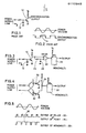
- FIGURE 1 shows a typical construction of the zero-cross level detection circuit which includes a transistor 10 and a diode 12.
- a system timing signal is obtained through the use of the leading edge or the trailing edge of a synchronization output derived from the zero-cross level detection circuit (see FIGURE 2).
- the frequency of the occurrence of the erroneous detection output 14 is considerably lower than the power frequency. Furthermore, the power frequency is normally known. Therefore, if a system is constructed to neglect the power voltage variation for a preselected period of time after the last edge has been detected, the erroneous detection output 14 will be removed.
- FIGURE 3 shows an embodiment of a power frequency detection system of the present invention.
- FIGURE 4 shows another embodiment of the power frequency detection system of the present invention.
- Two embodiments differ from each other at an edge detection section for detecting the zero-cross timing of the power supply voltage. Both embodiments include a monomultivibrator 20 (not retrig- gerable).
- the monomultivibrator 20 must be triggered by edges of a same polarity every half cycle of the power supply voltage.
- a detection output of a zero-cross level detection circuit which -includes the transistor 10 and the diode 12, is directly applied to one input terminal of an exclusive OR gate 22.
- the other input terminal of the exclusive OR gate 22 receives a delayed detection output of the zero-cross detection circuit via an integration circuit including a resistor 24 and a capacitor 26.
- An output signal of the exclusive OR gate 22 is applied to the monomultivibrator 20.
- a zero-cross level detection circuit includes photo-couplers 30 and 32 which function, in combination, as a wired OR gate.
- a point 34 provides a detection output signal as shown in FIGURE 5.
- the thus obtained detection output signal is applied to the monomultivibrator 20.
- the output signal of the exclusive OR gate 22 in FIGURE 3 or the output signal obtained at the point 34 in FIGURE 4 bears a high level when the power voltage polarity changes. That is, the output signals of the exclusive OR gate 22 and the photo-couplers 30 and 32 are the zero-cross detection signal.
- noises such as an erroneous detection signal 36 are neglected as long as the monomultivibrator 20 is in the set state. -That is, an output signal of the monomultivibrator 20 is not influenced by the erroneous detection signal 36.
- the pulse width of the monomultivibrator 20 is selected slightly shorter than one half of the period of the power supply voltage. In a preferred form, the pulse width of the monomultivibrator 20 is selected at 7.5 milliseconds when the power supply voltage has a frequency of 60 H z.
- a microcomputer is widely used in a control system of the power line signal transmission system.
- the microcomputer includes a programmable timer. By utilizing the programmable timer, a desired operation can be conducted as the circuits shown in FIGURES 3 and 4.
- FIGURE 6 shows an operational flow when the above-mentioned programmable timer is used to control the power frequency detection.
- the programmable timer is set to a desired value.
- the data processing is conducted.
- the above-mentioned edge detection is carried out.
- the programmable timer is again set to perform the next edge detection.
- a one-chip microcomputer'40 generally includes an input/ output port of the suspected bidirectional type. One of the bits can be used to form an analog integration timer as shown in FIGURE 7. More specifically, a resistor 42 and a capacitor 44 are connected to a terminal 46 of the microcomputer 40. The zero-cross level detection circuit including the transistor 10 and the diode 12 is connected to a terminal 48 of the microcomputer 40.
- FIGURE 8 shows signals occurring within the circuit of FIGURE 7.
- FIGURE 9 shows an operational flow of the circuit of FIGURE 7.
- the input/output bit is set to "1". Then, the data processing operation is conducted. Thereafter, a determination is conducted as to whether the introduced input/output bit (signal at the terminal 46) is "1". If an affirmative answer is obtained, the input/output bit is set to "0", and the edge detection operation is carried out.
- the timer set period T is represented as follows. where: C is the capacitance value of the capacitor 44, and R is the resistance value of the resistor 42.
- V th is about 1.4 volts, and V is 5 volts.
- k is 0.33.
- the one half period is 8.3 milliseconds.
- the capacitance value C of the capacitor 44 should be selected between 6.9 microfarads and 6.8 microfarads because the resistor 42 is generally selected at 3.3 kiloohms due to the sink current in the input/ output port (generally, 1.6 milliamperes).
Landscapes
- Physics & Mathematics (AREA)
- General Physics & Mathematics (AREA)
- Measurement Of Current Or Voltage (AREA)
- Remote Monitoring And Control Of Power-Distribution Networks (AREA)
- Measuring Frequencies, Analyzing Spectra (AREA)
Priority Applications (2)
| Application Number | Priority Date | Filing Date | Title |
|---|---|---|---|
| EP19820307005 EP0112948B1 (fr) | 1982-12-30 | 1982-12-30 | Système de détection de la fréquence du secteur |
| DE8282307005T DE3278795D1 (en) | 1982-12-30 | 1982-12-30 | Power frequency detection system |
Applications Claiming Priority (1)
| Application Number | Priority Date | Filing Date | Title |
|---|---|---|---|
| EP19820307005 EP0112948B1 (fr) | 1982-12-30 | 1982-12-30 | Système de détection de la fréquence du secteur |
Related Child Applications (2)
| Application Number | Title | Priority Date | Filing Date |
|---|---|---|---|
| EP19850112813 Division-Into EP0186740B1 (fr) | 1982-12-30 | 1982-12-30 | Système de détection de la fréquence du secteur |
| EP19850112813 Division EP0186740B1 (fr) | 1982-12-30 | 1982-12-30 | Système de détection de la fréquence du secteur |
Publications (2)
| Publication Number | Publication Date |
|---|---|
| EP0112948A1 true EP0112948A1 (fr) | 1984-07-11 |
| EP0112948B1 EP0112948B1 (fr) | 1988-07-20 |
Family
ID=8189882
Family Applications (1)
| Application Number | Title | Priority Date | Filing Date |
|---|---|---|---|
| EP19820307005 Expired EP0112948B1 (fr) | 1982-12-30 | 1982-12-30 | Système de détection de la fréquence du secteur |
Country Status (2)
| Country | Link |
|---|---|
| EP (1) | EP0112948B1 (fr) |
| DE (1) | DE3278795D1 (fr) |
Cited By (2)
| Publication number | Priority date | Publication date | Assignee | Title |
|---|---|---|---|---|
| EP0186740A1 (fr) * | 1982-12-30 | 1986-07-09 | Sharp Kabushiki Kaisha | Système de détection de la fréquence du secteur |
| CN103197129A (zh) * | 2013-04-10 | 2013-07-10 | 安徽节源节能科技有限公司 | 电力信号过零点检测方法 |
Citations (1)
| Publication number | Priority date | Publication date | Assignee | Title |
|---|---|---|---|---|
| DE2713945B1 (de) * | 1977-03-29 | 1978-01-05 | Siemens Ag | Schaltungsanordnung zur ermittlung der impulsabstaende und/oder folgefrequenz von impulsen einer impulsfolge |
-
1982
- 1982-12-30 EP EP19820307005 patent/EP0112948B1/fr not_active Expired
- 1982-12-30 DE DE8282307005T patent/DE3278795D1/de not_active Expired
Patent Citations (1)
| Publication number | Priority date | Publication date | Assignee | Title |
|---|---|---|---|---|
| DE2713945B1 (de) * | 1977-03-29 | 1978-01-05 | Siemens Ag | Schaltungsanordnung zur ermittlung der impulsabstaende und/oder folgefrequenz von impulsen einer impulsfolge |
Non-Patent Citations (2)
| Title |
|---|
| IBM TECHNICAL DISCLOSURE BULLETIN, vol. 24, no. 10, March 1982, pages 5025-5027, New York, USA * |
| PATENTS ABSTRACTS OF JAPAN, vol. 6, no. 141(P-131)(1019), 30th July 1982, Tokyo, JP. & JP - A - 57 64170 (TEAC K.K.) 19-04-1982 * |
Cited By (3)
| Publication number | Priority date | Publication date | Assignee | Title |
|---|---|---|---|---|
| EP0186740A1 (fr) * | 1982-12-30 | 1986-07-09 | Sharp Kabushiki Kaisha | Système de détection de la fréquence du secteur |
| CN103197129A (zh) * | 2013-04-10 | 2013-07-10 | 安徽节源节能科技有限公司 | 电力信号过零点检测方法 |
| CN103197129B (zh) * | 2013-04-10 | 2015-12-02 | 安徽节源节能科技有限公司 | 电力信号过零点检测方法 |
Also Published As
| Publication number | Publication date |
|---|---|
| EP0112948B1 (fr) | 1988-07-20 |
| DE3278795D1 (en) | 1988-08-25 |
Similar Documents
| Publication | Publication Date | Title |
|---|---|---|
| JPS63240451A (ja) | スマート制御及びセンサデバイス付シングルワイヤバスの多重化装置 | |
| US4412327A (en) | Test circuit for checking memory output state continuously during time window | |
| US4622478A (en) | Power frequency detection system | |
| US4853685A (en) | Switch monitoring arrangement with remote adjustment capability having debounce circuitry for accurate state determination | |
| EP0112948A1 (fr) | Système de détection de la fréquence du secteur | |
| EP0186740A1 (fr) | Système de détection de la fréquence du secteur | |
| US4852104A (en) | Solid-state reader device for a cumulative operations measurement system | |
| CA1198476A (fr) | Systeme de detection de frequence d'alimentation | |
| US5966034A (en) | Method and device for the filtering of a pulse signal | |
| KR890001272A (ko) | 신호 판별회로 | |
| JPH0133052B2 (fr) | ||
| JPH0627786B2 (ja) | 半導体集積回路装置 | |
| RU2143727C1 (ru) | Устройство для контроля функционирования блока обработки данных | |
| SU1707752A1 (ru) | Селектор импульсов | |
| SU1601607A1 (ru) | Устройство дл селекции сигналов поверки времени | |
| EP0501771A1 (fr) | Système de transmission d'information | |
| SU935832A1 (ru) | Устройство дл контрол сопротивлени изол ции | |
| KR880009323A (ko) | 주화 선택 장치 | |
| JP2984175B2 (ja) | 火災感知器 | |
| SU1458984A1 (ru) | Устройство дл автоматического определени ориентации микросхем | |
| SU1647551A1 (ru) | Емкостное устройство дл ввода данных | |
| SU1104448A1 (ru) | Устройство дл проверки электронных блоков | |
| RU2024906C1 (ru) | Устройство для допускового контроля временных интервалов | |
| JPH0556480A (ja) | 検波装置 | |
| US6636097B2 (en) | Method and input circuit for evaluating a data signal at an input of a memory component |
Legal Events
| Date | Code | Title | Description |
|---|---|---|---|
| PUAI | Public reference made under article 153(3) epc to a published international application that has entered the european phase |
Free format text: ORIGINAL CODE: 0009012 |
|
| AK | Designated contracting states |
Designated state(s): DE FR GB IT |
|
| 17P | Request for examination filed |
Effective date: 19840808 |
|
| ITF | It: translation for a ep patent filed | ||
| GRAA | (expected) grant |
Free format text: ORIGINAL CODE: 0009210 |
|
| AK | Designated contracting states |
Kind code of ref document: B1 Designated state(s): DE FR GB IT |
|
| REF | Corresponds to: |
Ref document number: 3278795 Country of ref document: DE Date of ref document: 19880825 |
|
| ET | Fr: translation filed | ||
| PLBE | No opposition filed within time limit |
Free format text: ORIGINAL CODE: 0009261 |
|
| STAA | Information on the status of an ep patent application or granted ep patent |
Free format text: STATUS: NO OPPOSITION FILED WITHIN TIME LIMIT |
|
| 26N | No opposition filed | ||
| ITTA | It: last paid annual fee | ||
| PGFP | Annual fee paid to national office [announced via postgrant information from national office to epo] |
Ref country code: FR Payment date: 19961211 Year of fee payment: 15 |
|
| PGFP | Annual fee paid to national office [announced via postgrant information from national office to epo] |
Ref country code: GB Payment date: 19961223 Year of fee payment: 15 |
|
| PGFP | Annual fee paid to national office [announced via postgrant information from national office to epo] |
Ref country code: DE Payment date: 19970107 Year of fee payment: 15 |
|
| PG25 | Lapsed in a contracting state [announced via postgrant information from national office to epo] |
Ref country code: GB Free format text: LAPSE BECAUSE OF NON-PAYMENT OF DUE FEES Effective date: 19971230 |
|
| PG25 | Lapsed in a contracting state [announced via postgrant information from national office to epo] |
Ref country code: FR Free format text: THE PATENT HAS BEEN ANNULLED BY A DECISION OF A NATIONAL AUTHORITY Effective date: 19971231 |
|
| GBPC | Gb: european patent ceased through non-payment of renewal fee |
Effective date: 19971230 |
|
| PG25 | Lapsed in a contracting state [announced via postgrant information from national office to epo] |
Ref country code: DE Free format text: LAPSE BECAUSE OF NON-PAYMENT OF DUE FEES Effective date: 19980901 |
|
| REG | Reference to a national code |
Ref country code: FR Ref legal event code: ST |