EP0113530B1 - Procédé et installation pour éliminer le méthane et l'argon de gaz de synthèse de l'ammoniac brut - Google Patents
Procédé et installation pour éliminer le méthane et l'argon de gaz de synthèse de l'ammoniac brut Download PDFInfo
- Publication number
- EP0113530B1 EP0113530B1 EP83307311A EP83307311A EP0113530B1 EP 0113530 B1 EP0113530 B1 EP 0113530B1 EP 83307311 A EP83307311 A EP 83307311A EP 83307311 A EP83307311 A EP 83307311A EP 0113530 B1 EP0113530 B1 EP 0113530B1
- Authority
- EP
- European Patent Office
- Prior art keywords
- synthesis gas
- ammonia synthesis
- gaseous stream
- liquid
- nitrogen
- Prior art date
- Legal status (The legal status is an assumption and is not a legal conclusion. Google has not performed a legal analysis and makes no representation as to the accuracy of the status listed.)
- Expired
Links
Images

Classifications
-
- F—MECHANICAL ENGINEERING; LIGHTING; HEATING; WEAPONS; BLASTING
- F25—REFRIGERATION OR COOLING; COMBINED HEATING AND REFRIGERATION SYSTEMS; HEAT PUMP SYSTEMS; MANUFACTURE OR STORAGE OF ICE; LIQUEFACTION SOLIDIFICATION OF GASES
- F25J—LIQUEFACTION, SOLIDIFICATION OR SEPARATION OF GASES OR GASEOUS OR LIQUEFIED GASEOUS MIXTURES BY PRESSURE AND COLD TREATMENT OR BY BRINGING THEM INTO THE SUPERCRITICAL STATE
- F25J3/00—Processes or apparatus for separating the constituents of gaseous or liquefied gaseous mixtures involving the use of liquefaction or solidification
- F25J3/02—Processes or apparatus for separating the constituents of gaseous or liquefied gaseous mixtures involving the use of liquefaction or solidification by rectification, i.e. by continuous interchange of heat and material between a vapour stream and a liquid stream
- F25J3/0204—Processes or apparatus for separating the constituents of gaseous or liquefied gaseous mixtures involving the use of liquefaction or solidification by rectification, i.e. by continuous interchange of heat and material between a vapour stream and a liquid stream characterised by the feed stream
- F25J3/0219—Refinery gas, cracking gas, coke oven gas, gaseous mixtures containing aliphatic unsaturated CnHm or gaseous mixtures of undefined nature
-
- C—CHEMISTRY; METALLURGY
- C01—INORGANIC CHEMISTRY
- C01B—NON-METALLIC ELEMENTS; COMPOUNDS THEREOF; METALLOIDS OR COMPOUNDS THEREOF NOT COVERED BY SUBCLASS C01C
- C01B3/00—Hydrogen; Gaseous mixtures containing hydrogen; Separation of hydrogen from mixtures containing it; Purification of hydrogen; Reversible storage of hydrogen
- C01B3/02—Production of hydrogen; Production of gaseous mixtures containing hydrogen
- C01B3/025—Preparation or purification of gas mixtures for ammonia synthesis
-
- F—MECHANICAL ENGINEERING; LIGHTING; HEATING; WEAPONS; BLASTING
- F25—REFRIGERATION OR COOLING; COMBINED HEATING AND REFRIGERATION SYSTEMS; HEAT PUMP SYSTEMS; MANUFACTURE OR STORAGE OF ICE; LIQUEFACTION SOLIDIFICATION OF GASES
- F25J—LIQUEFACTION, SOLIDIFICATION OR SEPARATION OF GASES OR GASEOUS OR LIQUEFIED GASEOUS MIXTURES BY PRESSURE AND COLD TREATMENT OR BY BRINGING THEM INTO THE SUPERCRITICAL STATE
- F25J3/00—Processes or apparatus for separating the constituents of gaseous or liquefied gaseous mixtures involving the use of liquefaction or solidification
- F25J3/02—Processes or apparatus for separating the constituents of gaseous or liquefied gaseous mixtures involving the use of liquefaction or solidification by rectification, i.e. by continuous interchange of heat and material between a vapour stream and a liquid stream
- F25J3/0228—Processes or apparatus for separating the constituents of gaseous or liquefied gaseous mixtures involving the use of liquefaction or solidification by rectification, i.e. by continuous interchange of heat and material between a vapour stream and a liquid stream characterised by the separated product stream
- F25J3/0233—Processes or apparatus for separating the constituents of gaseous or liquefied gaseous mixtures involving the use of liquefaction or solidification by rectification, i.e. by continuous interchange of heat and material between a vapour stream and a liquid stream characterised by the separated product stream separation of CnHm with 1 carbon atom or more
-
- F—MECHANICAL ENGINEERING; LIGHTING; HEATING; WEAPONS; BLASTING
- F25—REFRIGERATION OR COOLING; COMBINED HEATING AND REFRIGERATION SYSTEMS; HEAT PUMP SYSTEMS; MANUFACTURE OR STORAGE OF ICE; LIQUEFACTION SOLIDIFICATION OF GASES
- F25J—LIQUEFACTION, SOLIDIFICATION OR SEPARATION OF GASES OR GASEOUS OR LIQUEFIED GASEOUS MIXTURES BY PRESSURE AND COLD TREATMENT OR BY BRINGING THEM INTO THE SUPERCRITICAL STATE
- F25J3/00—Processes or apparatus for separating the constituents of gaseous or liquefied gaseous mixtures involving the use of liquefaction or solidification
- F25J3/02—Processes or apparatus for separating the constituents of gaseous or liquefied gaseous mixtures involving the use of liquefaction or solidification by rectification, i.e. by continuous interchange of heat and material between a vapour stream and a liquid stream
- F25J3/0228—Processes or apparatus for separating the constituents of gaseous or liquefied gaseous mixtures involving the use of liquefaction or solidification by rectification, i.e. by continuous interchange of heat and material between a vapour stream and a liquid stream characterised by the separated product stream
- F25J3/0252—Processes or apparatus for separating the constituents of gaseous or liquefied gaseous mixtures involving the use of liquefaction or solidification by rectification, i.e. by continuous interchange of heat and material between a vapour stream and a liquid stream characterised by the separated product stream separation of hydrogen
-
- F—MECHANICAL ENGINEERING; LIGHTING; HEATING; WEAPONS; BLASTING
- F25—REFRIGERATION OR COOLING; COMBINED HEATING AND REFRIGERATION SYSTEMS; HEAT PUMP SYSTEMS; MANUFACTURE OR STORAGE OF ICE; LIQUEFACTION SOLIDIFICATION OF GASES
- F25J—LIQUEFACTION, SOLIDIFICATION OR SEPARATION OF GASES OR GASEOUS OR LIQUEFIED GASEOUS MIXTURES BY PRESSURE AND COLD TREATMENT OR BY BRINGING THEM INTO THE SUPERCRITICAL STATE
- F25J3/00—Processes or apparatus for separating the constituents of gaseous or liquefied gaseous mixtures involving the use of liquefaction or solidification
- F25J3/02—Processes or apparatus for separating the constituents of gaseous or liquefied gaseous mixtures involving the use of liquefaction or solidification by rectification, i.e. by continuous interchange of heat and material between a vapour stream and a liquid stream
- F25J3/0228—Processes or apparatus for separating the constituents of gaseous or liquefied gaseous mixtures involving the use of liquefaction or solidification by rectification, i.e. by continuous interchange of heat and material between a vapour stream and a liquid stream characterised by the separated product stream
- F25J3/0257—Processes or apparatus for separating the constituents of gaseous or liquefied gaseous mixtures involving the use of liquefaction or solidification by rectification, i.e. by continuous interchange of heat and material between a vapour stream and a liquid stream characterised by the separated product stream separation of nitrogen
-
- F—MECHANICAL ENGINEERING; LIGHTING; HEATING; WEAPONS; BLASTING
- F25—REFRIGERATION OR COOLING; COMBINED HEATING AND REFRIGERATION SYSTEMS; HEAT PUMP SYSTEMS; MANUFACTURE OR STORAGE OF ICE; LIQUEFACTION SOLIDIFICATION OF GASES
- F25J—LIQUEFACTION, SOLIDIFICATION OR SEPARATION OF GASES OR GASEOUS OR LIQUEFIED GASEOUS MIXTURES BY PRESSURE AND COLD TREATMENT OR BY BRINGING THEM INTO THE SUPERCRITICAL STATE
- F25J3/00—Processes or apparatus for separating the constituents of gaseous or liquefied gaseous mixtures involving the use of liquefaction or solidification
- F25J3/02—Processes or apparatus for separating the constituents of gaseous or liquefied gaseous mixtures involving the use of liquefaction or solidification by rectification, i.e. by continuous interchange of heat and material between a vapour stream and a liquid stream
- F25J3/0228—Processes or apparatus for separating the constituents of gaseous or liquefied gaseous mixtures involving the use of liquefaction or solidification by rectification, i.e. by continuous interchange of heat and material between a vapour stream and a liquid stream characterised by the separated product stream
- F25J3/0276—Processes or apparatus for separating the constituents of gaseous or liquefied gaseous mixtures involving the use of liquefaction or solidification by rectification, i.e. by continuous interchange of heat and material between a vapour stream and a liquid stream characterised by the separated product stream separation of H2/N2 mixtures, i.e. of ammonia synthesis gas
-
- F—MECHANICAL ENGINEERING; LIGHTING; HEATING; WEAPONS; BLASTING
- F25—REFRIGERATION OR COOLING; COMBINED HEATING AND REFRIGERATION SYSTEMS; HEAT PUMP SYSTEMS; MANUFACTURE OR STORAGE OF ICE; LIQUEFACTION SOLIDIFICATION OF GASES
- F25J—LIQUEFACTION, SOLIDIFICATION OR SEPARATION OF GASES OR GASEOUS OR LIQUEFIED GASEOUS MIXTURES BY PRESSURE AND COLD TREATMENT OR BY BRINGING THEM INTO THE SUPERCRITICAL STATE
- F25J2200/00—Processes or apparatus using separation by rectification
- F25J2200/02—Processes or apparatus using separation by rectification in a single pressure main column system
-
- F—MECHANICAL ENGINEERING; LIGHTING; HEATING; WEAPONS; BLASTING
- F25—REFRIGERATION OR COOLING; COMBINED HEATING AND REFRIGERATION SYSTEMS; HEAT PUMP SYSTEMS; MANUFACTURE OR STORAGE OF ICE; LIQUEFACTION SOLIDIFICATION OF GASES
- F25J—LIQUEFACTION, SOLIDIFICATION OR SEPARATION OF GASES OR GASEOUS OR LIQUEFIED GASEOUS MIXTURES BY PRESSURE AND COLD TREATMENT OR BY BRINGING THEM INTO THE SUPERCRITICAL STATE
- F25J2200/00—Processes or apparatus using separation by rectification
- F25J2200/50—Processes or apparatus using separation by rectification using multiple (re-)boiler-condensers at different heights of the column
-
- F—MECHANICAL ENGINEERING; LIGHTING; HEATING; WEAPONS; BLASTING
- F25—REFRIGERATION OR COOLING; COMBINED HEATING AND REFRIGERATION SYSTEMS; HEAT PUMP SYSTEMS; MANUFACTURE OR STORAGE OF ICE; LIQUEFACTION SOLIDIFICATION OF GASES
- F25J—LIQUEFACTION, SOLIDIFICATION OR SEPARATION OF GASES OR GASEOUS OR LIQUEFIED GASEOUS MIXTURES BY PRESSURE AND COLD TREATMENT OR BY BRINGING THEM INTO THE SUPERCRITICAL STATE
- F25J2200/00—Processes or apparatus using separation by rectification
- F25J2200/74—Refluxing the column with at least a part of the partially condensed overhead gas
-
- F—MECHANICAL ENGINEERING; LIGHTING; HEATING; WEAPONS; BLASTING
- F25—REFRIGERATION OR COOLING; COMBINED HEATING AND REFRIGERATION SYSTEMS; HEAT PUMP SYSTEMS; MANUFACTURE OR STORAGE OF ICE; LIQUEFACTION SOLIDIFICATION OF GASES
- F25J—LIQUEFACTION, SOLIDIFICATION OR SEPARATION OF GASES OR GASEOUS OR LIQUEFIED GASEOUS MIXTURES BY PRESSURE AND COLD TREATMENT OR BY BRINGING THEM INTO THE SUPERCRITICAL STATE
- F25J2205/00—Processes or apparatus using other separation and/or other processing means
- F25J2205/02—Processes or apparatus using other separation and/or other processing means using simple phase separation in a vessel or drum
-
- F—MECHANICAL ENGINEERING; LIGHTING; HEATING; WEAPONS; BLASTING
- F25—REFRIGERATION OR COOLING; COMBINED HEATING AND REFRIGERATION SYSTEMS; HEAT PUMP SYSTEMS; MANUFACTURE OR STORAGE OF ICE; LIQUEFACTION SOLIDIFICATION OF GASES
- F25J—LIQUEFACTION, SOLIDIFICATION OR SEPARATION OF GASES OR GASEOUS OR LIQUEFIED GASEOUS MIXTURES BY PRESSURE AND COLD TREATMENT OR BY BRINGING THEM INTO THE SUPERCRITICAL STATE
- F25J2210/00—Processes characterised by the type or other details of the feed stream
- F25J2210/20—H2/N2 mixture, i.e. synthesis gas for or purge gas from ammonia synthesis
-
- F—MECHANICAL ENGINEERING; LIGHTING; HEATING; WEAPONS; BLASTING
- F25—REFRIGERATION OR COOLING; COMBINED HEATING AND REFRIGERATION SYSTEMS; HEAT PUMP SYSTEMS; MANUFACTURE OR STORAGE OF ICE; LIQUEFACTION SOLIDIFICATION OF GASES
- F25J—LIQUEFACTION, SOLIDIFICATION OR SEPARATION OF GASES OR GASEOUS OR LIQUEFIED GASEOUS MIXTURES BY PRESSURE AND COLD TREATMENT OR BY BRINGING THEM INTO THE SUPERCRITICAL STATE
- F25J2270/00—Refrigeration techniques used
- F25J2270/02—Internal refrigeration with liquid vaporising loop
-
- F—MECHANICAL ENGINEERING; LIGHTING; HEATING; WEAPONS; BLASTING
- F25—REFRIGERATION OR COOLING; COMBINED HEATING AND REFRIGERATION SYSTEMS; HEAT PUMP SYSTEMS; MANUFACTURE OR STORAGE OF ICE; LIQUEFACTION SOLIDIFICATION OF GASES
- F25J—LIQUEFACTION, SOLIDIFICATION OR SEPARATION OF GASES OR GASEOUS OR LIQUEFIED GASEOUS MIXTURES BY PRESSURE AND COLD TREATMENT OR BY BRINGING THEM INTO THE SUPERCRITICAL STATE
- F25J2270/00—Refrigeration techniques used
- F25J2270/04—Internal refrigeration with work-producing gas expansion loop
-
- F—MECHANICAL ENGINEERING; LIGHTING; HEATING; WEAPONS; BLASTING
- F25—REFRIGERATION OR COOLING; COMBINED HEATING AND REFRIGERATION SYSTEMS; HEAT PUMP SYSTEMS; MANUFACTURE OR STORAGE OF ICE; LIQUEFACTION SOLIDIFICATION OF GASES
- F25J—LIQUEFACTION, SOLIDIFICATION OR SEPARATION OF GASES OR GASEOUS OR LIQUEFIED GASEOUS MIXTURES BY PRESSURE AND COLD TREATMENT OR BY BRINGING THEM INTO THE SUPERCRITICAL STATE
- F25J2270/00—Refrigeration techniques used
- F25J2270/42—Quasi-closed internal or closed external nitrogen refrigeration cycle
-
- F—MECHANICAL ENGINEERING; LIGHTING; HEATING; WEAPONS; BLASTING
- F25—REFRIGERATION OR COOLING; COMBINED HEATING AND REFRIGERATION SYSTEMS; HEAT PUMP SYSTEMS; MANUFACTURE OR STORAGE OF ICE; LIQUEFACTION SOLIDIFICATION OF GASES
- F25J—LIQUEFACTION, SOLIDIFICATION OR SEPARATION OF GASES OR GASEOUS OR LIQUEFIED GASEOUS MIXTURES BY PRESSURE AND COLD TREATMENT OR BY BRINGING THEM INTO THE SUPERCRITICAL STATE
- F25J2270/00—Refrigeration techniques used
- F25J2270/88—Quasi-closed internal refrigeration or heat pump cycle, if not otherwise provided
-
- Y—GENERAL TAGGING OF NEW TECHNOLOGICAL DEVELOPMENTS; GENERAL TAGGING OF CROSS-SECTIONAL TECHNOLOGIES SPANNING OVER SEVERAL SECTIONS OF THE IPC; TECHNICAL SUBJECTS COVERED BY FORMER USPC CROSS-REFERENCE ART COLLECTIONS [XRACs] AND DIGESTS
- Y10—TECHNICAL SUBJECTS COVERED BY FORMER USPC
- Y10S—TECHNICAL SUBJECTS COVERED BY FORMER USPC CROSS-REFERENCE ART COLLECTIONS [XRACs] AND DIGESTS
- Y10S62/00—Refrigeration
- Y10S62/923—Inert gas
- Y10S62/924—Argon
-
- Y—GENERAL TAGGING OF NEW TECHNOLOGICAL DEVELOPMENTS; GENERAL TAGGING OF CROSS-SECTIONAL TECHNOLOGIES SPANNING OVER SEVERAL SECTIONS OF THE IPC; TECHNICAL SUBJECTS COVERED BY FORMER USPC CROSS-REFERENCE ART COLLECTIONS [XRACs] AND DIGESTS
- Y10—TECHNICAL SUBJECTS COVERED BY FORMER USPC
- Y10S—TECHNICAL SUBJECTS COVERED BY FORMER USPC CROSS-REFERENCE ART COLLECTIONS [XRACs] AND DIGESTS
- Y10S62/00—Refrigeration
- Y10S62/931—Recovery of hydrogen
- Y10S62/934—From nitrogen
Definitions
- This invention relates to a process and a plant for removing methane and argon from crude ammonia synthesis gas.
- ammonia is synthesized by passing crude ammonia synthesis gas (a mixture containing essentially 3 moles of hydrogen to every mole of nitrogen) through a catalytic reactor.
- crude ammonia synthesis gas a mixture containing essentially 3 moles of hydrogen to every mole of nitrogen
- the gas leaving the catalytic reactor is cooled to condense product ammonia whilst the unreacted gas is recycled to the catalytic reactor.
- the crude ammonia synthesis gas also contains small quantities of methane and argon which accumulate in the system. These impurities are generally kept at an acceptable level by continuously removing a portion of the unreacted gas as a purge. Apart from the loss of hydrogen and nitrogen in the purge the presence of argon and methane in the catalytic reactor tends to inhibit the desired production of ammonia.
- the methane and argon are removed together with a certain amount of nitrogen.
- the initial crude ammonia synthesis gas is enriched with nitrogen so that the gas passing through the catalytic reactor contains the requisite proportions of hydrogen to nitrogen.
- the volume of nitrogen will be such that the crude ammonia synthesis gas approaching the low temperature distillation units of GB-A-1,156,002 and 1,156,003 will contain between 35% and 40% (by volume) nitrogen.
- extra compression costs are incurred in compressing the extra nitrogen.
- some of the refrigeration required is obtained by expanding the crude ammonia synthesis gas. This necessitates the subsequent recompression of the purified ammonia synthesis gas.
- the crude ammonia synthesis gas will contain between 26% and 31 % by volume nitrogen, and more usually between 26% and 30% nitrogen, with between 27% and 28% nitrogen being preferred. This should be contrasted against the prior art where 35% is usual.
- steps (e) and (g) are carried out in the same heat exchanger as steps (a) and (i) although they could be carried out in a separate and distinct heat exchanger.
- step (e) part of the warmed gas from step (e) is compressed and introduced into said crude ammonia synthesis gas.
- the cooled crude ammonia synthesis gas enters step (b) wholly in the gaseous phase, preferably at or not more than 10°C above its dew point, and more preferably at or not more than 5°C above its dew point.
- part of the refrigeration required to achieve the distilling step (b) is provided by a condensed part of the cooled gaseous stream from step (g).
- the crude ammonia synthesis gas will contain more than 2% (argon+methane) by volume and the purified ammonia synthesis gas will contain less than 0.5% by volume (argon+methane).
- the present invention also provides a plant for removing methane and argon from crude ammonia synthesis gas, which plant comprises:-
- means (e) and (g) comprise said heat exchanger.
- Figure 1 is a simplified flow sheet of one embodiment of a plant in accordance with the invention.
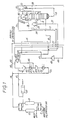
- Figure 2 is a simplified flow sheet of a second embodiment of a plant in accordance with the invention.
- moist crude ammonia synthesis gas at 29 bar absolute passes through pipe 11 and one of driers 12 and 13 to pipe 14.
- a liquid containing the bulk of the methane present in the crude ammonia synthesis gas together with nitrogen and some of the argon present in the crude ammonia synthesis gas leaves the sump of the distillation column 18 through pipe 19. It is then let down in pressure at valve 20, and the mainly liquid flow resulting is passed into vessel 80 where it is partially vaporized to form a liquid stream rich in methane and a gaseous stream rich in nitrogen.
- the liquid stream rich in methane leaves the vessel 80 through pipe 26 and is introduced into vessel 24 containing intermediate reflux condenser 23. Part of the liquid stream evaporates and the resulting vapour and liquid are passed through pipes 31 and 32 respectively to heat exchanger 15 wherein the liquid is vaporized. The vaporized liquid and vapour from pipe 31 are then warmed and leave the heat exchanger 15 through pipe 34 as methane rich fuel gas.
- the gaseous stream rich in nitrogen leaves the vessel 80 through pipe 25. It is subsequently joined by cold gas from pipe 49 and the combined stream is passed through pipe 27 to heat exchanger 15 wherein it assists in cooling the incoming gas. After passing through heat exchanger 15, the warmed stream passes through pipe 40. A minor part of the warmed stream is passed through pipe 61 and heater 62 to the driers 12 and 13 wherein it is used to assist in regeneration. The major part of the warmed stream is passed through pipe 41 to compressor 42 wherein it is compressed to about 6 bar A. It is then passed through pipe 43 to water cooler 44 which it leaves thorough pipe 45. The compressed gaseous stream is then divided into a first sub-stream and a second sub-stream.
- the first sub-stream passes through pipe 51 to compressor 52. After compression the gas passed through pipe 53 to water cooler 54, and then passed through pipe 55 to join the incoming crude ammonia synthesis gas.
- the second sub-stream is passed through pipe 46 to heat exchanger 15 wherein it is cooled to about -143°C before being passed through pipe 47 to expander 48 wherein it is expanded to 1.5 bars A.
- the cold expanded gas is passed through pipe 49 to its junction with pipe 25.
- Purified synthesis gas leaves the top of the distillation column 18 through pipe 82. Part is condensed in the main reflux condenser 22 and the resulting two phase mixture is separated in phase separator 83. Liquid is returned from the separator 83 through pipe 28 whilst the vapour is carried through pipe 29 to heat exchanger 15 where it is warmed and from which it leaves through pipe 30 as purified synthesis gas.
- compositions of various streams are given in Table 1.
- crude dry ammonia synthesis gas at 52.8 bar A in pipe 56' is cooled to -160°C in heat exchanger 15'.
- the gas leaves the heat exchange 2°C above its dew point (-162°C) and passes through pipe 16' into the distillation column 18' which has a main reflux condenser 22'.
- a liquid containing the bulk of the methane present in the crude ammonia synthesis gas together with some nitrogen and argon leaves the sump of the distillation column 18' through pipe 19'. It is then let down in pressure at valve 35 and is passed into separator 36 at a pressure of 20 bar A.
- a hydrogen-rich gas leaves separator 36 through pipe 57 and after being heated in heat exchanger 15' leaves the plant through line 58.
- Vessel 80' contains a reflux condenser 22'. Additional liquid nitrogen is introduced into vessel 80' as will be described later.
- the liquid stream rich in methane leaves the vessel 80' through pipe 26' and passes into heat exchanger 15' where it is vaporized before leaving the plant through pipe 34' as methane rich fuel gas.
- the gaseous stream rich in nitrogen leaves the vessel 80' through pipe 25'. It then passes through heat exchanger 38 and from there through pipe 39. It is subsequently joined by cold gas from pipe 49' and the combined stream is passed through pipe 27' to heat exchanger 15' where it assists in cooling the incoming gas. After passing through heat exchanger 15' the warmed stream passes through pipe 40'. Part of the warmed stream is passed through pipe 61' to feed driers (not shown) whilst the balance is passed through pipe 41'to compressor 42' wherein it is compressed to about 13 bar A. It is then passed through pipe 43'to water cooler 44' which it leaves through pipe 45'. It is then cooled to about -119°C in heat exchanger 15' wherein it is divided into a first sub-stream and a second sub-stream.
- the first sub-stream is cooled and condensed in the heat exchanger 15'.
- the condensed liquid leaves the heat exchanger 15' through pipe 63 and is let down in pressure at valve 64 before entering the vessel 80'.
- the second sub-stream passes through pipe 47' to expander 48' wherein it is expanded to about 2 bar A.
- the cold expanded gas is passed through pipe 49' to its junction with pipe 39.
- Purified synthesis gas leaves the top of the distillation column 18' through pipe 82'. Part is condensed in the main reflux condenser 22' and the resulting two phase mixture is separated in phase separator 83'. Liquid is returned from the separator 83' through pipe 28' whilst the vapour is carried through pipe 29' to heat exchanger 15' where it is warmed and from which it leaves through pipe 30' as purified synthesis gas.
- compositions of various streams are given in Table 2.
- the embodiment shown in Figure 2 has significant advantages over the embodiment shown in Figure 1. Firstly the compressor 52 is redundant. Secondly, the purified synthesis gas contains only 0.01 mole % methane impurity compared with about 0.23% methane impurity in the first embodiment.
- intermediate reflux condenser 23 shown in Figure 1 is an optional feature.
- a similar reflux condenser 23 could be used in the embodiment of Figure 2 if desired.
- the separator 36 and the heat exchanger 38 shown in Figure 2 are optional. Such features could also be applied to the embodiment shown in Figure 1.
- the crude ammonia synthesis gas for use in the present invention typically requires 26% to 31 %, (preferably 26% to 30% and more preferably 27% to 28%) by volume nitrogen to produce a purified ammonia synthesis gas having the required 3:1 proportions of hydrogen to nitrogen.
- the prior art processes described in GB-A-1,156,002 and 1,156,003 would require crude ammonia synthesis gas having at least 30% (by volume) nitrogen and typically around 35% nitrogen. The compression of this additional nitrogen in the prior art is a considerable cost penalty.
Landscapes
- Engineering & Computer Science (AREA)
- Physics & Mathematics (AREA)
- Mechanical Engineering (AREA)
- Thermal Sciences (AREA)
- General Engineering & Computer Science (AREA)
- Chemical & Material Sciences (AREA)
- Organic Chemistry (AREA)
- Combustion & Propulsion (AREA)
- Inorganic Chemistry (AREA)
- Separation By Low-Temperature Treatments (AREA)
Claims (9)
caractérisée en ce que ladite installation comprend en outre:
Priority Applications (1)
| Application Number | Priority Date | Filing Date | Title |
|---|---|---|---|
| AT83307311T ATE26964T1 (de) | 1982-12-23 | 1983-12-01 | Verfahren und anlage zum entfernen von methan und argon aus rohem ammoniak-synthesegas. |
Applications Claiming Priority (4)
| Application Number | Priority Date | Filing Date | Title |
|---|---|---|---|
| GB8236616 | 1982-12-23 | ||
| GB8236616 | 1982-12-23 | ||
| GB8311579 | 1983-04-28 | ||
| GB08311579A GB2132328B (en) | 1982-12-23 | 1983-04-28 | A process for removing methane and argon from crude ammonia synthesis gas] |
Publications (3)
| Publication Number | Publication Date |
|---|---|
| EP0113530A2 EP0113530A2 (fr) | 1984-07-18 |
| EP0113530A3 EP0113530A3 (en) | 1985-05-22 |
| EP0113530B1 true EP0113530B1 (fr) | 1987-05-06 |
Family
ID=26284764
Family Applications (1)
| Application Number | Title | Priority Date | Filing Date |
|---|---|---|---|
| EP83307311A Expired EP0113530B1 (fr) | 1982-12-23 | 1983-12-01 | Procédé et installation pour éliminer le méthane et l'argon de gaz de synthèse de l'ammoniac brut |
Country Status (6)
| Country | Link |
|---|---|
| US (1) | US4549890A (fr) |
| EP (1) | EP0113530B1 (fr) |
| CA (1) | CA1221021A (fr) |
| DE (1) | DE3371328D1 (fr) |
| GB (1) | GB2132328B (fr) |
| NO (1) | NO160573C (fr) |
Families Citing this family (24)
| Publication number | Priority date | Publication date | Assignee | Title |
|---|---|---|---|---|
| US4689062A (en) * | 1986-02-24 | 1987-08-25 | The Boc Group, Inc. | Argon recovery from ammonia plant purge gas utilizing a combination of cryogenic and non-cryogenic separating means |
| US4687498A (en) * | 1986-02-24 | 1987-08-18 | The Boc Group, Inc. | Argon recovery from hydrogen depleted ammonia plant purge gas utilizing a combination of cryogenic and non-cryogenic separating means |
| US4752311A (en) * | 1986-02-24 | 1988-06-21 | The Boc Group, Inc. | Argon recovery from ammonia plant purge gas utilizing a combination of cryogenic and non-cryogenic separating means |
| US4762542A (en) * | 1987-03-20 | 1988-08-09 | The Boc Group, Inc. | Process for the recovery of argon |
| FR2614612B1 (fr) * | 1987-04-28 | 1990-09-14 | Technip Cie | Procede de production amelioree de gaz d'ammoniac et installation pour l'execution de ce procede |
| US5100447A (en) * | 1990-08-30 | 1992-03-31 | The Boc Group, Inc. | Argon recovery from partial oxidation based ammonia plant purge gases |
| NO171966C (no) * | 1991-01-23 | 1993-05-26 | Norsk Hydro As | Fremgangsmaate for rensing av syntesegass for ammoniakkfremstilling |
| US5775128A (en) * | 1997-05-02 | 1998-07-07 | Praxair Technology, Inc. | Process for producing ammonia and recovering argon using low purity oxygen |
| FR2817766B1 (fr) * | 2000-12-13 | 2003-08-15 | Technip Cie | Procede et installation de separation d'un melange gazeux contenant du methane par distillation,et gaz obtenus par cette separation |
| US7090816B2 (en) * | 2003-07-17 | 2006-08-15 | Kellogg Brown & Root Llc | Low-delta P purifier for nitrogen, methane, and argon removal from syngas |
| US9126841B2 (en) | 2004-07-29 | 2015-09-08 | Fluor Technologies Corporation | Ammonia plant |
| DK1700823T3 (da) * | 2005-03-06 | 2011-05-30 | Ammonia Casale Sa | Fremgangsmåde til fremstilling af syntesegas |
| US8617270B2 (en) * | 2008-12-03 | 2013-12-31 | Kellogg Brown & Root Llc | Systems and methods for improving ammonia synthesis efficiency |
| DE102009003350C5 (de) * | 2009-01-14 | 2017-02-09 | Reicat Gmbh | Verfahren und Vorrichtung zur Abtrennung von Argon aus einem Gasgemisch |
| WO2011019335A1 (fr) | 2009-08-11 | 2011-02-17 | Fluor Technologies Corporation | Configurations et procédés de génération d'une vapeur d'eau basse pression |
| US8889093B2 (en) | 2010-09-16 | 2014-11-18 | Kellogg Brown & Root Llc | High pressure cyrogenic process and system for producing ammonia products |
| US8889037B2 (en) | 2011-02-01 | 2014-11-18 | Kellogg Brown & Root Llc | Systems and methods for producing syngas and products therefrom |
| CN103438662B (zh) * | 2013-08-21 | 2015-06-24 | 河南心连心深冷能源股份有限公司 | 回收合成氨尾气生产lng的装置及工艺方法 |
| US10295251B2 (en) * | 2016-09-21 | 2019-05-21 | Praxair Technology, Inc. | System and method for cryogenic purification of a feed stream comprising hydrogen, methane, nitrogen and argon |
| US10088229B2 (en) | 2016-09-21 | 2018-10-02 | Praxair Technology, Inc. | System and method for cryogenic purification of a feed stream comprising hydrogen, methane, nitrogen and argon |
| US10024595B2 (en) | 2016-09-21 | 2018-07-17 | Praxair Technology, Inc. | System and method for cryogenic purification of a feed stream comprising hydrogen, methane, nitrogen and argon |
| CN106766672B (zh) * | 2016-11-08 | 2019-05-31 | 苏州金宏气体股份有限公司 | 基于膨胀制冷提纯氨气的装置及用该装置提纯氨气的方法 |
| CN108178166B (zh) * | 2017-12-29 | 2020-10-13 | 新奥泛能网络科技股份有限公司 | 合成氨分离的方法和系统 |
| CN114777420B (zh) * | 2022-03-31 | 2024-08-02 | 中科瑞奥能源科技股份有限公司 | 氢体系中回收氩气和高纯甲烷的系统和方法 |
Family Cites Families (3)
| Publication number | Priority date | Publication date | Assignee | Title |
|---|---|---|---|---|
| BE593069A (fr) * | 1958-06-27 | 1900-01-01 | ||
| GB1156003A (en) * | 1965-10-22 | 1969-06-25 | Braun & Co C F | Ammonia Synthesis Gas Purification Process and Apparatus. |
| US4270939A (en) * | 1979-08-06 | 1981-06-02 | Air Products And Chemicals, Inc. | Separation of hydrogen containing gas mixtures |
-
1983
- 1983-04-28 GB GB08311579A patent/GB2132328B/en not_active Expired
- 1983-12-01 EP EP83307311A patent/EP0113530B1/fr not_active Expired
- 1983-12-01 DE DE8383307311T patent/DE3371328D1/de not_active Expired
- 1983-12-01 US US06/557,083 patent/US4549890A/en not_active Expired - Fee Related
- 1983-12-01 CA CA000442373A patent/CA1221021A/fr not_active Expired
- 1983-12-01 NO NO834421A patent/NO160573C/no unknown
Also Published As
| Publication number | Publication date |
|---|---|
| DE3371328D1 (en) | 1987-06-11 |
| NO160573C (no) | 1989-05-03 |
| CA1221021A (fr) | 1987-04-28 |
| US4549890A (en) | 1985-10-29 |
| EP0113530A3 (en) | 1985-05-22 |
| NO834421L (no) | 1984-06-25 |
| GB2132328A (en) | 1984-07-04 |
| GB2132328B (en) | 1986-03-26 |
| EP0113530A2 (fr) | 1984-07-18 |
| NO160573B (no) | 1989-01-23 |
| GB8311579D0 (en) | 1983-06-02 |
Similar Documents
| Publication | Publication Date | Title |
|---|---|---|
| EP0113530B1 (fr) | Procédé et installation pour éliminer le méthane et l'argon de gaz de synthèse de l'ammoniac brut | |
| US4372764A (en) | Method of producing gaseous oxygen and a cryogenic plant in which said method can be performed | |
| US4345925A (en) | Process for the production of high pressure oxygen gas | |
| US4704148A (en) | Cycle to produce low purity oxygen | |
| US4702757A (en) | Dual air pressure cycle to produce low purity oxygen | |
| US4254629A (en) | Cryogenic system for producing low-purity oxygen | |
| US5509271A (en) | Process and installation for the separation of a gaseous mixture | |
| US4629484A (en) | Process for separating hydrogen and methane from an ethylene rich stream | |
| US4749393A (en) | Process for the recovery of hydrogen/heavy hydrocarbons from hydrogen-lean feed gases | |
| EP0600513B1 (fr) | Procédé de production d'hélium par voie cryogénique | |
| US3675434A (en) | Separation of low-boiling gas mixtures | |
| US4895583A (en) | Apparatus and method for separating air | |
| US4952305A (en) | Process and apparatus for the separation of hydrocarbons | |
| EP0042676A1 (fr) | Méthode de production d'oxygène gazeux et installation cryogénique pour la mise en oeuvre de cette méthode | |
| US4338108A (en) | Process for the recovery of argon | |
| US3173778A (en) | Separation of gaseous mixtures including argon | |
| US5349822A (en) | Method and apparatus for the production of ultra-high purity nitrogen | |
| US4762542A (en) | Process for the recovery of argon | |
| EP0418139B1 (fr) | Procédé et dispositif pour la séparation cryogénique d'air | |
| US5602293A (en) | Process for separating a feedstock stream essentially consisting of hydrogen, methane and C3 /C4 -hydrocarbons | |
| US5123946A (en) | Cryogenic nitrogen generator with bottom reboiler and nitrogen expander | |
| US5144808A (en) | Cryogenic air separation process and apparatus | |
| US4765814A (en) | Process for purification of a gas stream by a nitrogen scrubbing | |
| US3433027A (en) | Hydrogen purification with condensate wash and hydrogen addition to condensate | |
| US6082134A (en) | Process and apparatus for separating a gaseous mixture |
Legal Events
| Date | Code | Title | Description |
|---|---|---|---|
| PUAI | Public reference made under article 153(3) epc to a published international application that has entered the european phase |
Free format text: ORIGINAL CODE: 0009012 |
|
| AK | Designated contracting states |
Designated state(s): AT BE CH DE FR IT LI LU NL SE |
|
| PUAL | Search report despatched |
Free format text: ORIGINAL CODE: 0009013 |
|
| AK | Designated contracting states |
Designated state(s): AT BE CH DE FR IT LI LU NL SE |
|
| 17P | Request for examination filed |
Effective date: 19850518 |
|
| 17Q | First examination report despatched |
Effective date: 19860520 |
|
| ITF | It: translation for a ep patent filed | ||
| GRAA | (expected) grant |
Free format text: ORIGINAL CODE: 0009210 |
|
| AK | Designated contracting states |
Kind code of ref document: B1 Designated state(s): AT BE CH DE FR IT LI LU NL SE |
|
| PG25 | Lapsed in a contracting state [announced via postgrant information from national office to epo] |
Ref country code: LI Effective date: 19870506 Ref country code: CH Effective date: 19870506 Ref country code: AT Effective date: 19870506 |
|
| REF | Corresponds to: |
Ref document number: 26964 Country of ref document: AT Date of ref document: 19870515 Kind code of ref document: T |
|
| PG25 | Lapsed in a contracting state [announced via postgrant information from national office to epo] |
Ref country code: SE Effective date: 19870531 |
|
| REF | Corresponds to: |
Ref document number: 3371328 Country of ref document: DE Date of ref document: 19870611 |
|
| ET | Fr: translation filed | ||
| REG | Reference to a national code |
Ref country code: CH Ref legal event code: PL |
|
| PG25 | Lapsed in a contracting state [announced via postgrant information from national office to epo] |
Ref country code: LU Free format text: LAPSE BECAUSE OF NON-PAYMENT OF DUE FEES Effective date: 19871231 Ref country code: BE Effective date: 19871231 |
|
| PLBE | No opposition filed within time limit |
Free format text: ORIGINAL CODE: 0009261 |
|
| STAA | Information on the status of an ep patent application or granted ep patent |
Free format text: STATUS: NO OPPOSITION FILED WITHIN TIME LIMIT |
|
| 26N | No opposition filed | ||
| BERE | Be: lapsed |
Owner name: AIR PRODUCTS AND CHEMICALS INC. Effective date: 19871231 |
|
| PG25 | Lapsed in a contracting state [announced via postgrant information from national office to epo] |
Ref country code: FR Free format text: LAPSE BECAUSE OF NON-PAYMENT OF DUE FEES Effective date: 19880831 |
|
| PG25 | Lapsed in a contracting state [announced via postgrant information from national office to epo] |
Ref country code: DE Effective date: 19880901 |
|
| REG | Reference to a national code |
Ref country code: FR Ref legal event code: ST |
|
| PG25 | Lapsed in a contracting state [announced via postgrant information from national office to epo] |
Ref country code: NL Effective date: 19890701 |
|
| NLV4 | Nl: lapsed or anulled due to non-payment of the annual fee |