EP0113619A1 - Vorrichtung zum Schneiden von Blöcken aus Granit, Marmor, Stein und anderen ähnlichen Produkten - Google Patents
Vorrichtung zum Schneiden von Blöcken aus Granit, Marmor, Stein und anderen ähnlichen Produkten Download PDFInfo
- Publication number
- EP0113619A1 EP0113619A1 EP83402401A EP83402401A EP0113619A1 EP 0113619 A1 EP0113619 A1 EP 0113619A1 EP 83402401 A EP83402401 A EP 83402401A EP 83402401 A EP83402401 A EP 83402401A EP 0113619 A1 EP0113619 A1 EP 0113619A1
- Authority
- EP
- European Patent Office
- Prior art keywords
- frame
- fluid
- holder frame
- blades
- blade holder
- Prior art date
- Legal status (The legal status is an assumption and is not a legal conclusion. Google has not performed a legal analysis and makes no representation as to the accuracy of the status listed.)
- Granted
Links
Images

Classifications
-
- B—PERFORMING OPERATIONS; TRANSPORTING
- B27—WORKING OR PRESERVING WOOD OR SIMILAR MATERIAL; NAILING OR STAPLING MACHINES IN GENERAL
- B27B—SAWS FOR WOOD OR SIMILAR MATERIAL; COMPONENTS OR ACCESSORIES THEREFOR
- B27B3/00—Gang saw mills; Other sawing machines with reciprocating saw blades, specially designed for length sawing of trunks
- B27B3/02—Gang saw mills; Other sawing machines with reciprocating saw blades, specially designed for length sawing of trunks with vertically-reciprocating saw frame
- B27B3/10—Saw frames or guides therefor
-
- B—PERFORMING OPERATIONS; TRANSPORTING
- B23—MACHINE TOOLS; METAL-WORKING NOT OTHERWISE PROVIDED FOR
- B23Q—DETAILS, COMPONENTS, OR ACCESSORIES FOR MACHINE TOOLS, e.g. ARRANGEMENTS FOR COPYING OR CONTROLLING; MACHINE TOOLS IN GENERAL CHARACTERISED BY THE CONSTRUCTION OF PARTICULAR DETAILS OR COMPONENTS; COMBINATIONS OR ASSOCIATIONS OF METAL-WORKING MACHINES, NOT DIRECTED TO A PARTICULAR RESULT
- B23Q1/00—Members which are comprised in the general build-up of a form of machine, particularly relatively large fixed members
- B23Q1/25—Movable or adjustable work or tool supports
- B23Q1/26—Movable or adjustable work or tool supports characterised by constructional features relating to the co-operation of relatively movable members; Means for preventing relative movement of such members
- B23Q1/38—Movable or adjustable work or tool supports characterised by constructional features relating to the co-operation of relatively movable members; Means for preventing relative movement of such members using fluid bearings or fluid cushion supports
-
- B—PERFORMING OPERATIONS; TRANSPORTING
- B23—MACHINE TOOLS; METAL-WORKING NOT OTHERWISE PROVIDED FOR
- B23Q—DETAILS, COMPONENTS, OR ACCESSORIES FOR MACHINE TOOLS, e.g. ARRANGEMENTS FOR COPYING OR CONTROLLING; MACHINE TOOLS IN GENERAL CHARACTERISED BY THE CONSTRUCTION OF PARTICULAR DETAILS OR COMPONENTS; COMBINATIONS OR ASSOCIATIONS OF METAL-WORKING MACHINES, NOT DIRECTED TO A PARTICULAR RESULT
- B23Q11/00—Accessories fitted to machine tools for keeping tools or parts of the machine in good working condition or for cooling work; Safety devices specially combined with or arranged in, or specially adapted for use in connection with, machine tools
- B23Q11/0032—Arrangements for preventing or isolating vibrations in parts of the machine
-
- B—PERFORMING OPERATIONS; TRANSPORTING
- B27—WORKING OR PRESERVING WOOD OR SIMILAR MATERIAL; NAILING OR STAPLING MACHINES IN GENERAL
- B27B—SAWS FOR WOOD OR SIMILAR MATERIAL; COMPONENTS OR ACCESSORIES THEREFOR
- B27B3/00—Gang saw mills; Other sawing machines with reciprocating saw blades, specially designed for length sawing of trunks
- B27B3/22—Gang saw mills; Other sawing machines with reciprocating saw blades, specially designed for length sawing of trunks with horizontally-reciprocating saw frame
- B27B3/26—Mechanisms for producing the reciprocating movement of the saw frame; Arrangements for damping vibrations; Arrangements for counter-balancing
-
- B—PERFORMING OPERATIONS; TRANSPORTING
- B28—WORKING CEMENT, CLAY, OR STONE
- B28D—WORKING STONE OR STONE-LIKE MATERIALS
- B28D1/00—Working stone or stone-like materials, e.g. brick, concrete or glass, not provided for elsewhere; Machines, devices, tools therefor
- B28D1/02—Working stone or stone-like materials, e.g. brick, concrete or glass, not provided for elsewhere; Machines, devices, tools therefor by sawing
- B28D1/06—Working stone or stone-like materials, e.g. brick, concrete or glass, not provided for elsewhere; Machines, devices, tools therefor by sawing with reciprocating saw-blades
- B28D1/068—Components, e.g. guiding means, vibrations damping means, frames, driving means, suspension
-
- Y—GENERAL TAGGING OF NEW TECHNOLOGICAL DEVELOPMENTS; GENERAL TAGGING OF CROSS-SECTIONAL TECHNOLOGIES SPANNING OVER SEVERAL SECTIONS OF THE IPC; TECHNICAL SUBJECTS COVERED BY FORMER USPC CROSS-REFERENCE ART COLLECTIONS [XRACs] AND DIGESTS
- Y10—TECHNICAL SUBJECTS COVERED BY FORMER USPC
- Y10T—TECHNICAL SUBJECTS COVERED BY FORMER US CLASSIFICATION
- Y10T83/00—Cutting
- Y10T83/687—By tool reciprocable along elongated edge
- Y10T83/688—With dynamic balancing or shock absorbing means
Definitions
- the present invention relates to a cutting device which can be used without modification for cutting any natural material, this device comprising blades arranged in a frame which is supported so that it can be moved in an alternating rectilinear movement or below a guide frame, itself movable vertically under the effect of jacks.
- the present invention creates a new machine which, being able to be provided with one to several tens of blades, allows the sawing of natural material whatever their hardness with the diamond tool, improves the quality of the sawn surfaces, the cutting conditions, production rates and therefore the cost price of this type of manufacturing. It is also indicated that improving the quality of sawing makes it possible, by obtaining a better condition of the surfaces, to save appreciable time on the subsequent surfacing and polishing operations.
- this device for cutting stones, marbles, granites and other similar products by means of diamond blades moved in an alternating movement by a blade-carrying frame, itself connected to a reciprocating motor assembly, is characterized in that at least the blade holder frame is connected to a sliding frame by vibration damping elements.
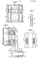
- Fig. 1 is an elevation, partly broken away and schematic, of a reciprocating sawing machine applying the invention.
- Fig. 2 is a front elevation corresponding to FIG. 1.
- Fig. 3 is a section taken substantially along line III-III of FIG. 1.
- Fig. 4 is a detail of one of the parts appearing in FIG. 3.
- Fig. 5 is a schematic section of another detail of embodiment.
- the machine illustrated in the drawing comprises rear uprights 1, 1a and front uprights 2, 2a which are arranged for example at the corners of a rectangular trapezoid.
- the uprights are connected by upper beams 3 and upper crosspieces 4.
- the uprights are surrounded by guide assemblies 5 to which is fixed a slide-holder frame 6.
- the slide-holder frame supports by means of suspension brackets 7 a blade-holder frame 8.
- the blades 9 of the frame 8 are intended for sawing a block 10, for example a block of granite.
- the blade holder frame 8 is provided laterally with at least one axis 11 for the articulation of the head of a connecting rod 12, the foot of which is articulated on an axis 13 mounted at the end of a crank 14 wedged on a shaft 15 carrying a flywheel 16 and driven by an electric motor 17 preferably at variable speed.
- the up and down movement of the blade holder frame 8 is controlled by that of the slide holder frame 6 and, in the example shown, this movement is provided by screws 18 placed in the uprights, the speed of rotation of the screws being synchronized by transmission boxes 19 interconnected by shafts 20 driven by a geared motor 21.
- a fluid connection is created between the various members subjected to a relative movement with respect to each other.
- each sliding device comprises a profile 23 on which slides 24, 25 are mounted. slides 24, 25 are held between pads 26, in the example, three in number. These pads are arranged in a casing 27 which is itself fixed to the side members of the slide-holder frame 6.
- Each shoe defines in its face turned towards the slide 24 at least one housing 28 which is supplied with pressurized fluid, for example oil, through a channel 29.
- Conduits 30 are provided for supplying each housing 28.
- the above arrangement makes it possible to maintain the slides in a state close to that of a levitation state and, consequently, on the one hand, to considerably reduce the friction when moving the blade-holder frame relative to the door frame -guides and, on the other hand, and above all, to prevent the transmission of vibrations due in particular to the friction existing between the blades 9 and the block 10 during sawing and to the vertical or horizontal drive system of the door frame - blades.
- the device described above can be implemented in a similar manner between the guide assemblies 5 and the uprights 1, la and 2, 2a.
- the axis 11 on which the head of the connecting rod 12 is articulated comprises a bearing box 31 containing arced pads 32 which delimit a housing 33 into which opens a pipe 34 pressurized fluid supply.
- the screws 18 whose rotation ensures the descent and then the ascent of the slide-holder frame are connected to the latter by nuts 35 (fig. 5) delimiting channels 36 connected to at least one collecting chamber 37 into which pressurized fluid is supplied via a pipe 38.
- the drawing shows that the channels 36 open into the bottom of the threads of the thread of the nut, which means that this nut whose threads are machined relative to that of the screw 18 is not in material contact with said screw.
- the nuts are provided with sealing bellows 39 or similar devices.
- the motor 17 is at variable speed, which makes it possible to vary the beat rate, for example adjusted in dependence on the nature of the block 10 to be sawn, and, on the other hand, to produce at least the crank 14 in the form of a telescopic element to allow the blade stroke to be varied, that is to say in particular to optimize the stroke as a function of block 10 and the compositions of the tool to allow the blades to be used always under optimal sawing conditions.
- the speed of the motor 17 is adjusted so that the maximum linear speed reached by the blades does not exceed a determined threshold.
- the gear motor 21 is for its part preferably also produced in the form of a variable speed assembly so that the speed of descent of the blades which determines the depth of each working pass during their sliding movement does not exceed a threshold pre-established.
- the possibility of continuously varying the stroke of the blades, the beat rate as well as the descent speed therefore allows control of the assembly by a microcomputer system having memorized the optimum combination of these settings.
- the invention is not limited to the embodiment shown and described in detail, because various modifications can be made without departing from its scope.
- the blade-holder frame 8 can be moved by preferably hydraulic and double-acting cylinders acting either directly on it or on the sliding devices 22.
- the geared motor assembly 17 and the steering wheel inertia 16 can be replaced by a hydraulic motor.
- the pads 26 as well as the pads 32 and the nut parts 36 may be constituted by the pole pieces of electromagnetic winding generating magnetic fields for maintaining in levitation state the pieces to be isolated to prevent transmission vibrations.
Landscapes
- Engineering & Computer Science (AREA)
- Mechanical Engineering (AREA)
- Life Sciences & Earth Sciences (AREA)
- Wood Science & Technology (AREA)
- Forests & Forestry (AREA)
- Mining & Mineral Resources (AREA)
- Processing Of Stones Or Stones Resemblance Materials (AREA)
- Devices For Post-Treatments, Processing, Supply, Discharge, And Other Processes (AREA)
- Laminated Bodies (AREA)
- Compositions Of Macromolecular Compounds (AREA)
- Control Of Cutting Processes (AREA)
- Finishing Walls (AREA)
- Road Signs Or Road Markings (AREA)
- Processing And Handling Of Plastics And Other Materials For Molding In General (AREA)
- Sawing (AREA)
Priority Applications (1)
| Application Number | Priority Date | Filing Date | Title |
|---|---|---|---|
| AT83402401T ATE19993T1 (de) | 1982-12-15 | 1983-12-13 | Vorrichtung zum schneiden von bloecken aus granit, marmor, stein und anderen aehnlichen produkten. |
Applications Claiming Priority (2)
| Application Number | Priority Date | Filing Date | Title |
|---|---|---|---|
| FR8221040 | 1982-12-15 | ||
| FR8221040A FR2537913A1 (fr) | 1982-12-15 | 1982-12-15 | Dispositif pour la coupe de blocs de granit, marbres, pierres et autres produits analogues |
Publications (2)
| Publication Number | Publication Date |
|---|---|
| EP0113619A1 true EP0113619A1 (de) | 1984-07-18 |
| EP0113619B1 EP0113619B1 (de) | 1986-05-28 |
Family
ID=9280133
Family Applications (1)
| Application Number | Title | Priority Date | Filing Date |
|---|---|---|---|
| EP83402401A Expired EP0113619B1 (de) | 1982-12-15 | 1983-12-13 | Vorrichtung zum Schneiden von Blöcken aus Granit, Marmor, Stein und anderen ähnlichen Produkten |
Country Status (13)
| Country | Link |
|---|---|
| US (1) | US4566427A (de) |
| EP (1) | EP0113619B1 (de) |
| JP (1) | JPS59171609A (de) |
| AT (1) | ATE19993T1 (de) |
| BR (1) | BR8306884A (de) |
| CA (1) | CA1221618A (de) |
| DE (2) | DE3363829D1 (de) |
| ES (1) | ES528056A0 (de) |
| FR (1) | FR2537913A1 (de) |
| GR (1) | GR78781B (de) |
| IN (1) | IN161345B (de) |
| MX (1) | MX158577A (de) |
| PT (1) | PT77828B (de) |
Cited By (1)
| Publication number | Priority date | Publication date | Assignee | Title |
|---|---|---|---|---|
| WO1990007071A1 (en) * | 1988-12-22 | 1990-06-28 | National Research Development Corporation | Mechanical devices and structures |
Families Citing this family (13)
| Publication number | Priority date | Publication date | Assignee | Title |
|---|---|---|---|---|
| US6196104B1 (en) | 1998-04-23 | 2001-03-06 | Premark Rwp Holdings, Inc. | Apparatus for producing sheets of solid surfacing |
| WO2000078517A1 (en) * | 1999-06-17 | 2000-12-28 | General Electric Company | Method and apparatus for cutting granite |
| US7089924B2 (en) * | 2001-12-14 | 2006-08-15 | Diamond Innovations, Inc. | Granite slabs cut with frame saw employing blades with diamond-containing segments and method of cutting thereof |
| US7082939B2 (en) * | 2002-12-10 | 2006-08-01 | Diamond Innovations, Inc. | Frame saw for cutting granite and method to improve performance of frame saw for cutting granite |
| ES2399398T3 (es) | 2003-08-14 | 2013-04-01 | Ehwa Diamond Industrial Co., Ltd. | Sistema para el corte del granito o materiales similares |
| CN104708110B (zh) * | 2013-12-13 | 2017-07-04 | 贵州中烟工业有限责任公司 | 升降可调式锯床 |
| WO2016170506A1 (en) * | 2015-04-22 | 2016-10-27 | Ism S.R.L. | Machine for cutting blocks of stone |
| CN205766904U (zh) * | 2016-05-13 | 2016-12-07 | 上海飞宙机械设备有限公司 | 一种锯条倾斜切割花岗岩、石英石的飞轮后置式排锯 |
| CN106042020A (zh) * | 2016-07-29 | 2016-10-26 | 无锡乐华自动化科技有限公司 | 一种固体垃圾切割装置 |
| CN106738365B (zh) * | 2017-01-13 | 2018-09-25 | 日照海恩锯业有限公司 | 一种用于切割花岗石的设备 |
| CN109909551A (zh) * | 2019-04-11 | 2019-06-21 | 桂林特邦新材料有限公司 | 金刚石绳锯防偏磨制备方法 |
| CN110549155B (zh) * | 2019-07-24 | 2021-11-30 | 湖北文理学院 | 一种削弱机床颤振的方法及机床结构 |
| CN114654537A (zh) * | 2022-04-15 | 2022-06-24 | 霍邱县亨兴工艺品有限公司 | 一种木制品的直边修正机 |
Citations (12)
| Publication number | Priority date | Publication date | Assignee | Title |
|---|---|---|---|---|
| BE661521A (de) * | ||||
| FR586320A (fr) * | 1924-04-29 | 1925-03-24 | Guidage à rouleaux pour cadres de scies horizontales et verticales à plusieurs lames | |
| DE904946C (de) * | 1951-12-14 | 1954-02-25 | Hermann Engels | Nachstellbare Gleitstuecke von hin und her gleitend gefuehrten Maschinenteilen, insbesondere fuer den in Staendern schwingenden Rahmen von Saegegattern |
| FR1193333A (fr) * | 1957-11-09 | 1959-11-02 | Dispositif amortisseur pour l'encadrement de scies sur machines à scier la pierre naturelle et machines semblables | |
| FR1299218A (fr) * | 1961-08-09 | 1962-07-20 | H A Waldrich | Système de commande à vis en particulier pour des machines-outils |
| FR1372163A (fr) * | 1963-10-04 | 1964-09-11 | Willy Sauter | Dispositif pour le graissage des surfaces de glissement des coulisses de chariots et pièces analogues |
| FR1440801A (de) * | 1966-08-31 | |||
| US3466951A (en) * | 1968-01-15 | 1969-09-16 | Babcock & Wilcox Co | Machine tools and instruments |
| FR2009748A1 (de) * | 1968-05-31 | 1970-02-06 | Philips Nv | |
| FR2032787A5 (de) * | 1969-02-08 | 1970-11-27 | Riv Officine Di Villar Perosa | |
| DE2161393A1 (de) * | 1971-12-10 | 1973-06-14 | Richard Flohr | Steingattersaege |
| US4040681A (en) * | 1973-05-21 | 1977-08-09 | U.S. Philips Corporation | Magnetically levitated object |
Family Cites Families (5)
| Publication number | Priority date | Publication date | Assignee | Title |
|---|---|---|---|---|
| US180344A (en) * | 1876-07-25 | Improvesvlent in stone-sawing wiachsnes | ||
| FR1035463A (fr) * | 1951-04-16 | 1953-08-25 | Machine pour scier le marbre | |
| US2816582A (en) * | 1954-04-30 | 1957-12-17 | Soderhamns Verkst Er Ab | Adjustable bearing means and lubrication system for reciprocating gang saws |
| US3197921A (en) * | 1962-08-17 | 1965-08-03 | Heald Machine Co | Grinding machine |
| US4105012A (en) * | 1975-08-20 | 1978-08-08 | Siemens Aktiengesellschaft | Apparatus for cutting up hard and brittle material |
-
1982
- 1982-12-15 FR FR8221040A patent/FR2537913A1/fr active Granted
-
1983
- 1983-12-13 DE DE8383402401T patent/DE3363829D1/de not_active Expired
- 1983-12-13 EP EP83402401A patent/EP0113619B1/de not_active Expired
- 1983-12-13 DE DE198383402401T patent/DE113619T1/de active Pending
- 1983-12-13 AT AT83402401T patent/ATE19993T1/de active
- 1983-12-14 ES ES528056A patent/ES528056A0/es active Granted
- 1983-12-14 US US06/561,020 patent/US4566427A/en not_active Expired - Fee Related
- 1983-12-14 GR GR73250A patent/GR78781B/el unknown
- 1983-12-14 BR BR8306884A patent/BR8306884A/pt not_active IP Right Cessation
- 1983-12-15 JP JP58235252A patent/JPS59171609A/ja active Granted
- 1983-12-15 PT PT77828A patent/PT77828B/pt not_active IP Right Cessation
- 1983-12-15 CA CA000443458A patent/CA1221618A/en not_active Expired
- 1983-12-15 IN IN1531/CAL/83A patent/IN161345B/en unknown
- 1983-12-15 MX MX199793A patent/MX158577A/es unknown
Patent Citations (12)
| Publication number | Priority date | Publication date | Assignee | Title |
|---|---|---|---|---|
| BE661521A (de) * | ||||
| FR1440801A (de) * | 1966-08-31 | |||
| FR586320A (fr) * | 1924-04-29 | 1925-03-24 | Guidage à rouleaux pour cadres de scies horizontales et verticales à plusieurs lames | |
| DE904946C (de) * | 1951-12-14 | 1954-02-25 | Hermann Engels | Nachstellbare Gleitstuecke von hin und her gleitend gefuehrten Maschinenteilen, insbesondere fuer den in Staendern schwingenden Rahmen von Saegegattern |
| FR1193333A (fr) * | 1957-11-09 | 1959-11-02 | Dispositif amortisseur pour l'encadrement de scies sur machines à scier la pierre naturelle et machines semblables | |
| FR1299218A (fr) * | 1961-08-09 | 1962-07-20 | H A Waldrich | Système de commande à vis en particulier pour des machines-outils |
| FR1372163A (fr) * | 1963-10-04 | 1964-09-11 | Willy Sauter | Dispositif pour le graissage des surfaces de glissement des coulisses de chariots et pièces analogues |
| US3466951A (en) * | 1968-01-15 | 1969-09-16 | Babcock & Wilcox Co | Machine tools and instruments |
| FR2009748A1 (de) * | 1968-05-31 | 1970-02-06 | Philips Nv | |
| FR2032787A5 (de) * | 1969-02-08 | 1970-11-27 | Riv Officine Di Villar Perosa | |
| DE2161393A1 (de) * | 1971-12-10 | 1973-06-14 | Richard Flohr | Steingattersaege |
| US4040681A (en) * | 1973-05-21 | 1977-08-09 | U.S. Philips Corporation | Magnetically levitated object |
Cited By (1)
| Publication number | Priority date | Publication date | Assignee | Title |
|---|---|---|---|---|
| WO1990007071A1 (en) * | 1988-12-22 | 1990-06-28 | National Research Development Corporation | Mechanical devices and structures |
Also Published As
| Publication number | Publication date |
|---|---|
| GR78781B (de) | 1984-10-02 |
| FR2537913B1 (de) | 1985-03-29 |
| ES8406277A1 (es) | 1984-08-01 |
| EP0113619B1 (de) | 1986-05-28 |
| CA1221618A (en) | 1987-05-12 |
| US4566427A (en) | 1986-01-28 |
| ATE19993T1 (de) | 1986-06-15 |
| BR8306884A (pt) | 1984-07-24 |
| MX158577A (es) | 1989-02-15 |
| JPS59171609A (ja) | 1984-09-28 |
| PT77828A (fr) | 1984-01-01 |
| DE3363829D1 (en) | 1986-07-03 |
| FR2537913A1 (fr) | 1984-06-22 |
| ES528056A0 (es) | 1984-08-01 |
| PT77828B (fr) | 1986-03-27 |
| JPH0356525B2 (de) | 1991-08-28 |
| IN161345B (de) | 1987-11-14 |
| DE113619T1 (de) | 1985-02-28 |
Similar Documents
| Publication | Publication Date | Title |
|---|---|---|
| EP0113619B1 (de) | Vorrichtung zum Schneiden von Blöcken aus Granit, Marmor, Stein und anderen ähnlichen Produkten | |
| EP1320438B1 (de) | Drahtsäge mit mitteln zum erzeugen einer zwischen werkstück und draht relativen oszillationsbewegung | |
| EP0788859A1 (de) | Drahtsägevorrichtung | |
| CH698391B1 (fr) | Dispositif de sciage par fil. | |
| CH665380A5 (en) | Cutting machine for brittle materials e.g. during electronic component - has cutting wire(s) driven by roller system to engage workpiece in abrasive liquid bath | |
| FR2607052A1 (fr) | Perfectionnements apportes aux machines a bois, telles que profileuses et profileuses-calibreuses, utilisees en menuiserie et ebenisterie, plus particulierement pour la fabrication de cadres en bois | |
| EP0554629B1 (de) | Honmaschine mit ausdehnbarem Werkzeug | |
| CH696757A5 (fr) | Procédé et dispositif de sciage par fil. | |
| WO1989010825A1 (fr) | Dispositif pour l'amelioration du sciage d'une piece en tranches fines | |
| EP0518799B1 (de) | Feinstbearbeitungsmaschine mit kombinierter Umdrehung und Hin- und Herbewegung des Werkzeuges | |
| FR2478517A1 (fr) | Procede et dispositif pour commander les mouvements d'avance et de degagement, notamment dans les trancheuses a bois | |
| US623742A (en) | Grinding or polishing machine | |
| EP1038633B1 (de) | Vorrichtung zur Schleifbearbeitung von Werkstücken, insbesondere zur Feinstbearbeitung | |
| FR2481975A1 (fr) | Machine et procede pour la finition d'usinage d'une piece metallique | |
| FR2725394A1 (fr) | Machine-outil pour usiner des pieces selon un profil determine | |
| FR2703286A1 (fr) | Procédé d'usinage des chants de dalles de pierre et appareil le mettant en Óoeuvre. | |
| FR2474364A1 (fr) | Aleseuse a broche ascendante | |
| CH571929A5 (en) | Method of grinding small components - involves using guide cam for tool working at constant loading | |
| BE454643A (de) | ||
| FR2655285A1 (fr) | Machine a affuter les couteaux. | |
| CH312313A (fr) | Machine à couper les tubes. | |
| FR2503608A1 (fr) | Dispositif pour l'usinage de surfaces coniques par electro-erosion | |
| FR2694512A1 (fr) | Tour d'usinage à commande numérique autonome. | |
| BE464818A (de) | ||
| EP0771247A1 (de) | Verfahren und vorrichtung zum bearbeiten eines werkstückes durch spanabhebung und werkstücke hergestellt durch dieses verfahren |
Legal Events
| Date | Code | Title | Description |
|---|---|---|---|
| PUAI | Public reference made under article 153(3) epc to a published international application that has entered the european phase |
Free format text: ORIGINAL CODE: 0009012 |
|
| 17P | Request for examination filed |
Effective date: 19831216 |
|
| AK | Designated contracting states |
Designated state(s): AT BE DE GB IT NL SE |
|
| ITCL | It: translation for ep claims filed |
Representative=s name: STUDIO ING. ALFREDO RAIMONDI |
|
| TCNL | Nl: translation of patent claims filed | ||
| TCAT | At: translation of patent claims filed | ||
| DET | De: translation of patent claims | ||
| ITF | It: translation for a ep patent filed | ||
| GRAA | (expected) grant |
Free format text: ORIGINAL CODE: 0009210 |
|
| AK | Designated contracting states |
Kind code of ref document: B1 Designated state(s): AT BE DE GB IT NL SE |
|
| REF | Corresponds to: |
Ref document number: 19993 Country of ref document: AT Date of ref document: 19860615 Kind code of ref document: T |
|
| REF | Corresponds to: |
Ref document number: 3363829 Country of ref document: DE Date of ref document: 19860703 |
|
| PLBE | No opposition filed within time limit |
Free format text: ORIGINAL CODE: 0009261 |
|
| STAA | Information on the status of an ep patent application or granted ep patent |
Free format text: STATUS: NO OPPOSITION FILED WITHIN TIME LIMIT |
|
| 26N | No opposition filed | ||
| ITTA | It: last paid annual fee | ||
| PGFP | Annual fee paid to national office [announced via postgrant information from national office to epo] |
Ref country code: GB Payment date: 19911213 Year of fee payment: 9 |
|
| PGFP | Annual fee paid to national office [announced via postgrant information from national office to epo] |
Ref country code: BE Payment date: 19921130 Year of fee payment: 10 |
|
| PG25 | Lapsed in a contracting state [announced via postgrant information from national office to epo] |
Ref country code: GB Effective date: 19921213 |
|
| PGFP | Annual fee paid to national office [announced via postgrant information from national office to epo] |
Ref country code: SE Payment date: 19921217 Year of fee payment: 10 |
|
| PGFP | Annual fee paid to national office [announced via postgrant information from national office to epo] |
Ref country code: AT Payment date: 19921229 Year of fee payment: 10 |
|
| GBPC | Gb: european patent ceased through non-payment of renewal fee |
Effective date: 19921213 |
|
| PG25 | Lapsed in a contracting state [announced via postgrant information from national office to epo] |
Ref country code: AT Effective date: 19931213 |
|
| PG25 | Lapsed in a contracting state [announced via postgrant information from national office to epo] |
Ref country code: SE Effective date: 19931214 |
|
| PG25 | Lapsed in a contracting state [announced via postgrant information from national office to epo] |
Ref country code: BE Effective date: 19931231 |
|
| BERE | Be: lapsed |
Owner name: ROCAMAT Effective date: 19931231 |
|
| EUG | Se: european patent has lapsed |
Ref document number: 83402401.0 Effective date: 19940710 |
|
| PGFP | Annual fee paid to national office [announced via postgrant information from national office to epo] |
Ref country code: DE Payment date: 19961211 Year of fee payment: 14 |
|
| PGFP | Annual fee paid to national office [announced via postgrant information from national office to epo] |
Ref country code: NL Payment date: 19961224 Year of fee payment: 14 |
|
| PG25 | Lapsed in a contracting state [announced via postgrant information from national office to epo] |
Ref country code: NL Free format text: LAPSE BECAUSE OF NON-PAYMENT OF DUE FEES Effective date: 19980701 |
|
| NLV4 | Nl: lapsed or anulled due to non-payment of the annual fee |
Effective date: 19980701 |
|
| PG25 | Lapsed in a contracting state [announced via postgrant information from national office to epo] |
Ref country code: DE Free format text: LAPSE BECAUSE OF NON-PAYMENT OF DUE FEES Effective date: 19980901 |