EP0113976A2 - Verfahren zum Einlegen von elastischen Bändern in hygienischen Produkten - Google Patents
Verfahren zum Einlegen von elastischen Bändern in hygienischen Produkten Download PDFInfo
- Publication number
- EP0113976A2 EP0113976A2 EP83307621A EP83307621A EP0113976A2 EP 0113976 A2 EP0113976 A2 EP 0113976A2 EP 83307621 A EP83307621 A EP 83307621A EP 83307621 A EP83307621 A EP 83307621A EP 0113976 A2 EP0113976 A2 EP 0113976A2
- Authority
- EP
- European Patent Office
- Prior art keywords
- elastic band
- combined elastic
- web
- suction
- combined
- Prior art date
- Legal status (The legal status is an assumption and is not a legal conclusion. Google has not performed a legal analysis and makes no representation as to the accuracy of the status listed.)
- Granted
Links
Images

Classifications
-
- A—HUMAN NECESSITIES
- A61—MEDICAL OR VETERINARY SCIENCE; HYGIENE
- A61F—FILTERS IMPLANTABLE INTO BLOOD VESSELS; PROSTHESES; DEVICES PROVIDING PATENCY TO, OR PREVENTING COLLAPSING OF, TUBULAR STRUCTURES OF THE BODY, e.g. STENTS; ORTHOPAEDIC, NURSING OR CONTRACEPTIVE DEVICES; FOMENTATION; TREATMENT OR PROTECTION OF EYES OR EARS; BANDAGES, DRESSINGS OR ABSORBENT PADS; FIRST-AID KITS
- A61F13/00—Bandages or dressings; Absorbent pads
- A61F13/15—Absorbent pads, e.g. sanitary towels, swabs or tampons for external or internal application to the body; Supporting or fastening means therefor; Tampon applicators
- A61F13/15577—Apparatus or processes for manufacturing
- A61F13/15585—Apparatus or processes for manufacturing of babies' napkins, e.g. diapers
- A61F13/15593—Apparatus or processes for manufacturing of babies' napkins, e.g. diapers having elastic ribbons fixed thereto; Devices for applying the ribbons
-
- Y—GENERAL TAGGING OF NEW TECHNOLOGICAL DEVELOPMENTS; GENERAL TAGGING OF CROSS-SECTIONAL TECHNOLOGIES SPANNING OVER SEVERAL SECTIONS OF THE IPC; TECHNICAL SUBJECTS COVERED BY FORMER USPC CROSS-REFERENCE ART COLLECTIONS [XRACs] AND DIGESTS
- Y10—TECHNICAL SUBJECTS COVERED BY FORMER USPC
- Y10T—TECHNICAL SUBJECTS COVERED BY FORMER US CLASSIFICATION
- Y10T156/00—Adhesive bonding and miscellaneous chemical manufacture
- Y10T156/10—Methods of surface bonding and/or assembly therefor
- Y10T156/1052—Methods of surface bonding and/or assembly therefor with cutting, punching, tearing or severing
- Y10T156/1062—Prior to assembly
- Y10T156/1075—Prior to assembly of plural laminae from single stock and assembling to each other or to additional lamina
-
- Y—GENERAL TAGGING OF NEW TECHNOLOGICAL DEVELOPMENTS; GENERAL TAGGING OF CROSS-SECTIONAL TECHNOLOGIES SPANNING OVER SEVERAL SECTIONS OF THE IPC; TECHNICAL SUBJECTS COVERED BY FORMER USPC CROSS-REFERENCE ART COLLECTIONS [XRACs] AND DIGESTS
- Y10—TECHNICAL SUBJECTS COVERED BY FORMER USPC
- Y10T—TECHNICAL SUBJECTS COVERED BY FORMER US CLASSIFICATION
- Y10T156/00—Adhesive bonding and miscellaneous chemical manufacture
- Y10T156/10—Methods of surface bonding and/or assembly therefor
- Y10T156/1089—Methods of surface bonding and/or assembly therefor of discrete laminae to single face of additional lamina
- Y10T156/1092—All laminae planar and face to face
- Y10T156/1093—All laminae planar and face to face with covering of discrete laminae with additional lamina
- Y10T156/1095—Opposed laminae are running length webs
Definitions
- This invention relates to a method for attaching an elastic band to sanitary articles.
- this method of prior art is disadvantageous in that the finished diaper will have unsealed areas at opposite ends so as to allow the unsealed portions of the elastic band to contract and thereby a urine leakage may occur through these unsealed areas.
- the elastic band attached to said web is transported in a continuous state over a relatively long distance from the initial step of attaching said elastic band to said web towards the final step of cutting said elastic band together with said web with adhesive applied on said elastic band remaining still not set, so that the elastic band may be sometimes displaced transversely of said web in the course of transport thereof and finally prevented from being properly attached to the web at a predetermined position.
- An object of the present invention is, in view of such disadvantages as mentioned above, to provide a method so improved that a continuous elastic band having adhesive applied thereon is previously cut into predetermined lengths and these lengths of the elastic band are intermittently attached to a continuously moving web forming interconnected articles.
- Another object of the present invention is to provide a method so improved that the continuously moving web to which the elastic band cut into said . predetermined lengths has been intermittently attached may be severed in the areas where said elastic band is not present not only to obtain the individual articles but also to seal the severed ends of said articles.
- a further object of the present invention is to provide a method so improved that the elastic band previously cut into predetermined lengths is attached to the web in the initial step of manufacture of the articles, as has previously been described, and thereby said elastic band may be surely kept against a displacement transverse of said web or a separation therefrom.
- a method for intermittently attaching an elastic band, in a stretched condition, with adhesive, to a continuously moving web forming interconnected articles such as sanitary articles on each side thereof longitudinally at predetermined intervals comprising the steps of: continuously or intermittently applying adhesive on the continuously moving elastic band in a stretched .condition; superposing said elastic band on a continuously moving support tape having a sufficiently high flexibility not to hinder a given expansion and contraction ability of said elastic band and a width larger than that of said elastic band and then nipping such assembly between a first pair of nip rollers to form a combined elastic band; continuously feeding said combined elastic band onto a surface of a rotary suction drum and severing said combined elastic band by a cutter adapted to be opposed to the surface of said suction drum when the latter has rotated by a predetermined angle; intermittently feeding said combined elastic band which has been severed and isolated on the surface of said suction drum into the predetermined lengths onto.
- each side and longitudinally of the web being continuously fed around a second nip roller placed to be opposed to said suction drum so as to form the interconnected articles; and severing said web transversely of said web in the areas defined ---between the longitudinal ends of the respectively adjacent lengths of the severed combined elastic band attached to said web to form the individual articles.
- the combined elastic band is severed on the surface of the rotary suction drum into predetermined lengths which are automatically spaced from one another at a distance at which these lengths of the combined elastic band are to be intermittently attached to the web.
- the present invention will find its most preferred application in forming a so-called disposable diaper, although the present invention is not limited to this field of application.
- a continuous elastic band 11 is continuously fed through pairs of draft rollers 12, 13; 14, 15 to a pair of nip rollers 16, 17.
- a circumferential velocity of the pair of draft rollers 14,15 is adjusted higher than that of the pair of draft rollers 12,13 so that the elastic band 11 may be stretched at a predetermined ratio.
- An applicator 18 continuously or intermittently applies on the elastic band 11 hot-melt adhesive having an elasticity.
- a continuous support tape 19 of material such as plastic film or nonwoven fabric having a flexibility sufficiently high not to hinder a predeter- mind expansion and contraction ability of the elastic band 11 and a width of 10 to 70mm, preferably 20 to 40mm is continuously fed through a guide roller 20 to the pair of nip rollers 16,17 under a predetermined tension.
- the elastic band 11 is attached to the support tape integrally therewith in a stretched condition between the pair of nip rollers 16,17.
- a primary purpose of attaching the elastic band to the support tape 19 is to assure that said elastic band can be reliably held on a suction drum (which will be described in more detail later) even when said elastic band has a relative narrow width.
- a combined elastic band 21 an assembly of the elastic band 11 thus attached to the support tape 19 will be referred to hereinafter as a combined elastic band 21.
- This combined elastic band 21 is continuously fed through a pair of tension rollers 22,23 onto a peripheral surface of a rotary suction drum 24.
- a rotary cutter 25 Opposed to said surface of the suction drum 24 is a rotary cutter 25 adapted to be synchronously operated every time said drum has rotated by a predetermined angle.
- a circumferential velocity of the suction drum 24 is set to a level higher than that at which the combined elastic band 21 is fed from the pair of tension rollers 22, 23 so that the combined elastic band 21 is severed into predetermined lengths on the surface of the suction drum 24 and simultaneously these severed lengths are automaticalJ spaced from one another at predetermined intervals (this aspect will be described in detail later).
- the combined elastic band 21 thus severed and its severed lengths spaced from one another is intermittently attached at said predetermined intervals with interposition of said adhesive applied on the elastic band 11 to a continuous web 30 which is continuously fed through guide rollers 27, 28, 29 to a nip roller 26 placed to face the surface of said suction drum 24 and having the same circumferential velocity as that of said drum.
- the web 30 is made of plastic film or like destined to be ultimately formed into a water-impervious backsheet.
- This web 30 with intermittently attached band 21 is fed to a pair of nip rollers 33,34 having the same circumferential velocity as that of the suction drum 24 as well as of the nip roller 26 and both placed to face an assembly station 32 while maintained in a : predetermined tension.
- a continuous web 35 of nonwoven fabric or like destined to be ultimately, formed into a water-pervious topsheet and having hot-melt adhesive previously applied thereon from an applicator 36 for attaching said web 35 to an absorbent core of the diaper and/or the continuous web 30 is fed to the assembly station 32 while maintained in a predetermined tension.
- the absorbent cores 37 prefabricated of fluffly pulp or like are fed at predetermined intervals to said assembly station 32 by a belt conveyor 38 having the same linear velocity as those of the webs 30, 35.
- the respective absorbent cores 37 are interposed between the webs 30,35 at predetermined intervals and these components are bonded in unison at this assembly station 32.
- Such sealing effect may be achieved, for example, either by heat seal occurring simultaneously with the severance or by previously applying adhesive on the inner surfaces of the respective webs 30,35 in the areas adjacent the respective severance lines and exerting a pressure to these adhesive areas while these webs 30,35 are severed.
- said draft roller 16 and said tension roller 23 on their peripheral surfaces with suitable means to prevent adhesive applied on said elastic band 11 from clinging to said peripheral surfaces, for example, to coat said peripheral surfaces with mold release agent such as silicon film, since said adhesive on said elastic band 11 is inevitably brought into contact with said peripheral surfaces.
- Said rollers 22, 23 may be draft rollers.
- said rollers 16, 23 are chilling rollers in which cooling water is circulated.
- Said elastic band 11 preferably comprises a plurality of fine rubber strands each having a relatively low tensile stress. If such a plurality of rubber strands is employed in the method according to the present invention, however, it is preferred to provide between said pairs of draft rollers 14, 15 and nip rollers 16, 17 a suitable means ensuring that said respective fine rubber strands are maintained at predetermined spacings from one another transversely of said support tape 19 when attached to this support tape 19, or to interpose between said respective pairs of rollers a separate roller provided on its peripheral surface with guide grooves for said respective rubber strands at predetermined intervals longitudinally of said peripheral surface.
- Fig. 2 illustrates by way of example the suction drum 24 and feeding of said combined elastic band 21 to this suction drum.
- the rotary suction drum 24 is defined by a porous peripheral wall carrying on its outer surface counter knives 44a, 44b, 44c, 44d cooperating with an edge 43 of the rotary cutter 25 and has within said peripheral wall a stationary suction zone 45 and a stationary non-suction zone 46, both always held at their predetermined positions as shown.
- the suction zone 45 extends between a position P 1 appropriately spaced in a direction opposite to rotation of the suction drum 24 from a position,of the cutter 25 at which the combined elastic band 21 is severed to a position P z adjacent a position at which the surfaces of said drum and the draft roller 26 are closest to each other.
- the suction drum 24 has its circumferential velocity set to a level higher than the velocity at which the combined elastic band 21 is fed from the tension rollers 22, 23 and the suction zone 45 provides an effective force always maintained at a sufficient level to hold the combined elastic band 21 onto the surface of said suction zone 45 even with slippage of said combined elastic band 21 along said surface.
- the respective pairs of adjacent counter knives 44a, 44b, 44c, 44d have center-distances larger than the predetermined lengths into which the combined elastic band 21 is severed.
- the suction drum 24 and the cutter 25 are so controlled that the edge 43 and the counter knives 44a, 44b, 44c, 44d are synchronously opposed to each other. Accordingly, the combined elastic band 21 is cut by the edge 43 of the cutter 24 on the surface of the drum associated with the suction zone 45 and a new leading end of the combined elastic band 21 formed every time said combined elastic band has been severed slips along said surface associated with the suction zone 45 against the effect of this zone while maintained in tension on said surface.
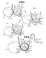
- FIG. 3(A), (B) and (C) illustrates a process in which this predetermined distance L 1 occurs. Specifically, Fig. 3(A) illustrates a state at a moment when the combined elastic band 21 is cut by the edge 43 of the cutter 25 in cooperation with the counter knife 44a; Fig.
- FIG. 3(B) illustrates a state in which the suction drum 24 has rotated.by a certain angle and a distance L 2 from the new leading end of the combined elastic band 21 formed after every severance to the trailing end of the severed and isolated length of the combined elastic band 21a, is being progressively enlarged to said predetermined distance L 1 ; and Fig. 3(C) illustrates a state at a moment when said distance L 2 has been enlarged -just to said predetermined value L 1 and now said remaining combined elastic band 21 is going to be cut by the edge 43 of the cutter 25 in cooperation with the counter knife 44a behind said new leading end thereof.
- Each length 21a thus severed and isolated from the remaining combined elastic band 21 is fed with its leading end ahead, as said length 21a moved together with the drum surface into the non-suction zone 46, onto the continuously moving web 30 and intermittently attached by said adhesive applied on said elastic band 11 to said web 30 (see Fig. 5).
- Fig. 4 illustrates another embodiment of said suction drum 24 itself and feeding said combined elastic band 21 to said suction drum 24.
- the velocity at which the combined elastic band 21 is fed by the tension rollers 22, 23 corresponds to the circumferential velocity of the rotary suction drum 124.
- This suction drum 124 has the stationary suction zone 145 and the stationary non-suction zone 146 as in the previous embodiment of Fig. 2, but the suction drum 124 is distinguished from the suction drum 24 in that the former additionally has a second stationary non-suction zone 50.
- a portion of the drum surface associated with the second non-suction zone 50 has a span substantially corresponding to the intervals at which the respective lengths 21a severed and isolated from the combined elastic,band 21 are intermittently attached to the web 30.
- the leading end of the combined elastic band 21 travels together with the drum surface while fixedly held onto the surface portion associated with the suction zone 145 across the non-suction zone 50.
- the trailing end of the length 21a severed and isolated from the remaining combined elastic band 21 is spaced from the new leading end of said remaining combined elastic .--band 21 formed after every severance by a distance substantially equal to said distance L 1 as said leading end and said trailing end (or the leading end of said elastic band 11 and the trailing end of said support tape 19) contract in the event said adhesive has continuously been applied on said elastic band 11 of the combined elastic band 21 (21a) and as the leading end and the trailing end only of the elastic band 11 contract if said adhesive has been intermittently applied on said elastic band 11 so that the latter is severed in the areas where no adhesive has been applied at all.
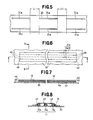
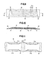
- Figs. 5 through 10 illustrate a manner in which said lengths 21a severed and isolated from the remaining combined elastic band 21 have been attached to the web 30 and three fine,rubber strands 11a are employed as said elastic band 11.
- the respective rubber strands 11a are attached by elastic hot-melt adhesive 47 applied completely around these respective rubber strands to said support tape 19 at predetermined intervals transversely'of said support tape 19.
- Figs. 5 through 8 further illustrate a state in which said adhesive 47 has been continuously applied along a full length of each rubber strand 11a and severed ends 48 of the rubber strands 11a are aligned with the corresponding severed ends 49 of the support tape 19 when these two components have been attached to each other.
- Figs. 9 and 10 illustrate also a state in which the respective rubber strands 11a having said adhesive 47 intermittently applied therealong have been cut in areas 51 where no adhesive has been applied and, in consequence, these non-adhesive areas have been retracted with respect to the severed ends 49 of the support tape 19.
- said respective rubber strands 11a those having a unit cross-sectional area of 0.03 to 0.6 mm 2 per strand and total cross-sectional area of 0.12 to 2.7 mm 2 at a state corresponding to an elongation percentage of 100 to 400%.
- said elastic holt-melt adhesive 47 a pressure-sensitive adhesive of room temperature setting type is one of those .preferred.
- Said adhesive 47 is cooled in a step after said combined elastic band 21 (21a) has been nipped by the draft rollers 16, 17 and before said combined elastic band 21 (21a) is cut by the cutter 25 to a temperature at which a desired room temperature setting property is exhibited.
- said elastic band 11 comprises said plurality of rubber strands 11a
- the individual rubber strand has a relatively low tensile stress.
- said elastic band 11 remains attached to said support tape 19 with a high stability and there is no danger that said elastic band 11 might contract on said support tape or might be separated therefrom even after said elastic band 11 has been cut by the cutter 25 together with said support tape 19.
- said combined elastic bands 21a intermittently attached to said web 30 also remain attached to said web with a high stability at least in the step before movement to said draft roller 26, since said adhesive 47 is spread over said support tape 19 under a pressure in said step and thereby said support tape is also attached to said web 30.
- the disposable diaper was manufactured by following the steps as illustrated by Figs. 1 and 2.
- each strand having a diameter of 0.28 mm, the assembly thus welded together having a cross-sectional area of 0.123 mm 2 and weighing 0.13 g/mm, were stretched by 400% through a draft roller so that each strand had a tensile stress of 30g.
- the severed and isolated portions of the combined elastic band were intermittently fed onto a backsheet of polyethylene film having a thickness of 30 ⁇ obtained by a high pressure process so that both components may be attached to each other under a nipping effect of a draft roller opposed to said suction drum. Thereafter the procedure as previously described with reference with Fig. 1 was followed to form a diaper.
Landscapes
- Health & Medical Sciences (AREA)
- Engineering & Computer Science (AREA)
- Animal Behavior & Ethology (AREA)
- Veterinary Medicine (AREA)
- Biomedical Technology (AREA)
- Heart & Thoracic Surgery (AREA)
- Vascular Medicine (AREA)
- Life Sciences & Earth Sciences (AREA)
- Manufacturing & Machinery (AREA)
- General Health & Medical Sciences (AREA)
- Public Health (AREA)
- Epidemiology (AREA)
- Absorbent Articles And Supports Therefor (AREA)
- Laminated Bodies (AREA)
- Orthopedics, Nursing, And Contraception (AREA)
- Package Frames And Binding Bands (AREA)
- Lining Or Joining Of Plastics Or The Like (AREA)
- Blow-Moulding Or Thermoforming Of Plastics Or The Like (AREA)
- Shaping Of Tube Ends By Bending Or Straightening (AREA)
Priority Applications (1)
| Application Number | Priority Date | Filing Date | Title |
|---|---|---|---|
| AT83307621T ATE26645T1 (de) | 1982-12-15 | 1983-12-15 | Verfahren zum einlegen von elastischen baendern in hygienischen produkten. |
Applications Claiming Priority (2)
| Application Number | Priority Date | Filing Date | Title |
|---|---|---|---|
| JP57219833A JPS59112010A (ja) | 1982-12-15 | 1982-12-15 | 使い捨て衛生物品に弾性部材を取り付ける方法 |
| JP219833/82 | 1982-12-15 |
Publications (3)
| Publication Number | Publication Date |
|---|---|
| EP0113976A2 true EP0113976A2 (de) | 1984-07-25 |
| EP0113976A3 EP0113976A3 (en) | 1984-08-08 |
| EP0113976B1 EP0113976B1 (de) | 1987-04-22 |
Family
ID=16741757
Family Applications (1)
| Application Number | Title | Priority Date | Filing Date |
|---|---|---|---|
| EP83307621A Expired EP0113976B1 (de) | 1982-12-15 | 1983-12-15 | Verfahren zum Einlegen von elastischen Bändern in hygienischen Produkten |
Country Status (9)
| Country | Link |
|---|---|
| US (1) | US4525229A (de) |
| EP (1) | EP0113976B1 (de) |
| JP (1) | JPS59112010A (de) |
| AT (1) | ATE26645T1 (de) |
| AU (1) | AU569715B2 (de) |
| CA (1) | CA1238882A (de) |
| DE (1) | DE3371034D1 (de) |
| ES (1) | ES528423A0 (de) |
| MX (1) | MX158148A (de) |
Cited By (10)
| Publication number | Priority date | Publication date | Assignee | Title |
|---|---|---|---|---|
| EP0154068A1 (de) * | 1984-03-05 | 1985-09-11 | H.B. Fuller Company | Verfahren und Einrichtung zum Führen und Anbringen von Material |
| FR2607366A1 (fr) * | 1986-12-02 | 1988-06-03 | Boussac Saint Freres Bsf | Couche-culotte a elastiques longitudinaux, et procede de fabrication en continu de telles couches-culottes |
| EP0301431A1 (de) * | 1987-07-30 | 1989-02-01 | Peaudouce | Höschenwindel mit elastischen Seiten und Verfahren zu ihrer Herstellung |
| FR2618645A1 (fr) * | 1987-07-30 | 1989-02-03 | Boussac Saint Freres Bsf | Couche-culotte a jeter a elastiques d'entre-jambe et enduction laterale d'etancheite |
| WO1994005500A1 (en) * | 1992-09-04 | 1994-03-17 | The Procter & Gamble Company | Method for continuously attaching a restrained elastic material to an absorbent article |
| WO1995010255A1 (en) * | 1993-10-14 | 1995-04-20 | The Procter & Gamble Company | An apparatus and process for cyclically accelerating and decelerating a strip of material |
| WO1997045261A1 (en) * | 1996-05-31 | 1997-12-04 | Sca Hygiene Products Ab | An elastic laminate for an absorbing article, and a method of producing the elastic laminate |
| WO1998025767A1 (en) * | 1996-12-09 | 1998-06-18 | SCA Mölnlycke AB | A method of producing an intermittent elastic web |
| EP2301876A4 (de) * | 2008-06-30 | 2011-10-05 | Unicharm Corp | Taktweise betriebene schneid- und transfervorrichtung |
| EP2301875A4 (de) * | 2008-06-30 | 2011-10-05 | Unicharm Corp | Taktweise betriebene schneid- und transfervorrichtung |
Families Citing this family (33)
| Publication number | Priority date | Publication date | Assignee | Title |
|---|---|---|---|---|
| JPS58180601A (ja) * | 1982-04-14 | 1983-10-22 | ユニ・チヤ−ム株式会社 | 使い捨ておむつ |
| IT1161511B (it) * | 1983-10-12 | 1987-03-18 | Fameccanica Spa | Procedimento ed apparecchiatura per la formazione di elementi elastici in tensione a partire da un nastro elastico continuo particolarmente per la fabbricazione di prodotti sanitari quali pannolini mono uso e simili |
| US4884563A (en) * | 1985-03-01 | 1989-12-05 | Ferris Mfg. Corp. | Non-stretching wound dressing and method for making same |
| JPS62161363A (ja) * | 1986-01-10 | 1987-07-17 | ユニ・チヤ−ム株式会社 | 衣類に対する衛生物品の止着手段を設ける方法および装置 |
| US4726807A (en) * | 1986-04-10 | 1988-02-23 | Weyerhaeuser Company | Diaper with elastic margins |
| US4925520A (en) * | 1988-08-11 | 1990-05-15 | Curt G. Joa, Inc. | Apparatus for applying an elastic waistband transversely of a longitudinally moving web |
| US4995928A (en) * | 1988-10-31 | 1991-02-26 | Sabee Reinhardt N | Method and apparatus for forming and transporting elastic ribbons |
| FR2639536A1 (fr) * | 1988-11-30 | 1990-06-01 | Peaudouce | Couche-culotte a elastiques d'entre-jambes |
| CA2050023C (en) * | 1991-04-22 | 2002-03-05 | Kimberly-Clark Worldwide, Inc. | Elongated element comprising helically patterned adhesive |
| US5271787A (en) * | 1991-05-24 | 1993-12-21 | Wallace Computer Services, Inc. | Method of making and using a label-equipped form |
| ZA92308B (en) | 1991-09-11 | 1992-10-28 | Kimberly Clark Co | Thin absorbent article having rapid uptake of liquid |
| US5275676A (en) * | 1992-09-18 | 1994-01-04 | Kimberly-Clark Corporation | Method and apparatus for applying a curved elastic to a moving web |
| US5667609A (en) * | 1996-02-14 | 1997-09-16 | The Procter & Gamble Company | Method for attaching barrier cuffs to disposable absorbent article |
| US5702551A (en) * | 1996-04-03 | 1997-12-30 | The Procter & Gamble Company | Method for assembling a multi-piece absorbent article |
| US6043406A (en) * | 1998-02-27 | 2000-03-28 | Ferris Mfg, Corp. | Thin film wound dressing and method for making same |
| US6077375A (en) * | 1998-04-15 | 2000-06-20 | Illinois Tool Works Inc. | Elastic strand coating process |
| US6165306A (en) * | 1998-06-01 | 2000-12-26 | Kimberly-Clark Worldwide, Inc. | Process and apparatus for cutting of discrete components of a multi-component workpiece and depositing them with registration on a moving web of material |
| US6074333A (en) * | 1998-12-24 | 2000-06-13 | Kimberly-Clark Worldwide, Inc. | Machine for cutting discrete components of a multi-component workpiece and depositing them with registration on a moving web of material |
| US6059710A (en) * | 1998-12-24 | 2000-05-09 | Kimberly-Clark Worldwide, Inc. | Process for cutting of discrete components of a multi-component workpiece and depositing them with registration on a moving web of material |
| ES2169648B1 (es) * | 2000-02-01 | 2003-02-16 | Com De Tecnologia Sanitaria S | Maquina para la fabricacion de productos multicapa, tales como compresas, protectores higienicos o apositos. |
| JP4474620B2 (ja) * | 2000-03-14 | 2010-06-09 | ノードソン株式会社 | 糸状又は紐状物体に接着剤を塗布する装置と方法 |
| US6719846B2 (en) | 2000-03-14 | 2004-04-13 | Nordson Corporation | Device and method for applying adhesive filaments to materials such as strands or flat substrates |
| US20030066593A1 (en) * | 2001-10-05 | 2003-04-10 | Alberto Kopelowicz | Elastic band |
| US7047852B2 (en) * | 2001-10-24 | 2006-05-23 | Kimberly-Clark Worldwide, Inc. | Feedforward control system for an elastic material |
| US6915829B2 (en) * | 2002-07-15 | 2005-07-12 | Kimberly-Clark Worldwide, Inc. | Apparatus and method for cutting and placing limp pieces of material |
| US20040081794A1 (en) * | 2002-10-29 | 2004-04-29 | Titone David M. | Method for applying adhesive filaments to multiple strands of material and articles formed with the method |
| US20040167493A1 (en) * | 2003-02-21 | 2004-08-26 | Sca Hygiene Products Ab | Arrangement and method for applying elastic element to a material web |
| US7854022B2 (en) | 2005-01-10 | 2010-12-21 | Hbi Branded Apparel Enterprises, Llc | Garments having seamless edge bands and processes for making same |
| CN100493864C (zh) * | 2007-07-28 | 2009-06-03 | 安庆市恒昌机械制造有限责任公司 | 一次性卫生用品生产线上的悬臂式切断转移装置 |
| US10993849B2 (en) | 2010-09-16 | 2021-05-04 | Dsg Technology Holdings Ltd. | Article with chassis having an elastic distribution, absorbent core and system and method for making same |
| SG10201507694SA (en) | 2010-09-16 | 2015-10-29 | Dsg Technology Holdings Ltd | Article with Elastic Distribution and System and Method for Making Same |
| US10524966B2 (en) | 2015-02-26 | 2020-01-07 | Dsg Technology Holdings Ltd. | Disposable absorbent core and disposable absorbent assembly including same, and method of making same |
| KR102648531B1 (ko) * | 2016-12-22 | 2024-03-19 | 디에스지 테크놀러지 홀딩스 리미티드 | 일회용 부유 흡수 코어 및 이를 포함하는 일회용 흡수 어셈블리, 및 이의 제조 방법 |
Family Cites Families (13)
| Publication number | Priority date | Publication date | Assignee | Title |
|---|---|---|---|---|
| US3772120A (en) * | 1971-11-05 | 1973-11-13 | Joa C Inc | Method for applying attaching tapes to pads |
| US3963557A (en) * | 1974-05-28 | 1976-06-15 | Minnesota Mining And Manufacturing Company | Article transferring apparatus |
| US4081301A (en) * | 1975-10-30 | 1978-03-28 | The Procter & Gamble Company | Method and apparatus for continuously attaching discrete, stretched elastic strands to predetermined isolated portions of disposable abosrbent products |
| US4285747A (en) * | 1979-10-18 | 1981-08-25 | Johnson & Johnson Baby Products Company | Method for manufacturing a product having elastic means disposed in the transverse direction |
| DE3016197A1 (de) * | 1980-04-26 | 1981-11-05 | Winkler & Dünnebier, Maschinenfabrik und Eisengießerei GmbH & Co KG, 5450 Neuwied | Verfahren und vorrichtung zum abschnittsweisen aufbringen elastischer streifen auf eine materialbahn zur herstellung von hoeschenwindeln o.dgl. |
| US4297157A (en) * | 1980-06-23 | 1981-10-27 | Weyerhaeuser Company | Method for application of elastic to articles |
| CA1146129A (en) * | 1980-08-22 | 1983-05-10 | Edmund Radzins | Apparatus for applying elastic ribbon segments to diapers |
| US4397704A (en) * | 1980-10-20 | 1983-08-09 | Kimberly-Clark Corporation | Method and apparatus for applying discrete lengths of elastic strip material to a continuously moving web |
| US4413623A (en) * | 1981-02-17 | 1983-11-08 | Johnson & Johnson Baby Products Company | Laminated structures having gathered and ungathered marginal portions and method of manufacturing the same |
| US4360398A (en) * | 1981-03-09 | 1982-11-23 | Sabee Products, Inc. | Method for applying elastic bands to webs |
| US4417935A (en) * | 1981-10-13 | 1983-11-29 | Paper Converting Machine Company | Method of diaper manufacture |
| JPS58174603A (ja) * | 1982-04-07 | 1983-10-13 | ユニ・チヤ−ム株式会社 | 使い捨ておむつにおける弾性部材の取付装置 |
| CA1195963A (en) * | 1982-06-21 | 1985-10-29 | Kimberly-Clark Corporation | Apparatus and method for contouring elastic ribbon on disposable garments |
-
1982
- 1982-12-15 JP JP57219833A patent/JPS59112010A/ja active Granted
-
1983
- 1983-12-14 US US06/561,479 patent/US4525229A/en not_active Expired - Lifetime
- 1983-12-14 AU AU22394/83A patent/AU569715B2/en not_active Expired
- 1983-12-14 CA CA000443262A patent/CA1238882A/en not_active Expired
- 1983-12-15 AT AT83307621T patent/ATE26645T1/de not_active IP Right Cessation
- 1983-12-15 DE DE8383307621T patent/DE3371034D1/de not_active Expired
- 1983-12-15 EP EP83307621A patent/EP0113976B1/de not_active Expired
- 1983-12-15 ES ES528423A patent/ES528423A0/es active Granted
- 1983-12-15 MX MX199776A patent/MX158148A/es unknown
Cited By (18)
| Publication number | Priority date | Publication date | Assignee | Title |
|---|---|---|---|---|
| EP0154068A1 (de) * | 1984-03-05 | 1985-09-11 | H.B. Fuller Company | Verfahren und Einrichtung zum Führen und Anbringen von Material |
| FR2607366A1 (fr) * | 1986-12-02 | 1988-06-03 | Boussac Saint Freres Bsf | Couche-culotte a elastiques longitudinaux, et procede de fabrication en continu de telles couches-culottes |
| EP0270979A3 (en) * | 1986-12-02 | 1988-07-20 | Boussac Saint Freres B.S.F. | Napkin with elastic bands extending longitudinally, and method for manufacturing this article |
| EP0301431A1 (de) * | 1987-07-30 | 1989-02-01 | Peaudouce | Höschenwindel mit elastischen Seiten und Verfahren zu ihrer Herstellung |
| FR2618645A1 (fr) * | 1987-07-30 | 1989-02-03 | Boussac Saint Freres Bsf | Couche-culotte a jeter a elastiques d'entre-jambe et enduction laterale d'etancheite |
| EP0304631A1 (de) * | 1987-07-30 | 1989-03-01 | Peaudouce | Wegwerfbare Höschenwindel mit elastischen und wasserdichten Beinabschlüssen |
| US4850989A (en) * | 1987-07-30 | 1989-07-25 | Peaudouce | Diaper with elastic on outer cover |
| US5100398A (en) * | 1987-07-30 | 1992-03-31 | Peaudouce | Disposable diaper with crotch elastics and lateral sealing coating |
| WO1994005500A1 (en) * | 1992-09-04 | 1994-03-17 | The Procter & Gamble Company | Method for continuously attaching a restrained elastic material to an absorbent article |
| WO1995010255A1 (en) * | 1993-10-14 | 1995-04-20 | The Procter & Gamble Company | An apparatus and process for cyclically accelerating and decelerating a strip of material |
| WO1997045261A1 (en) * | 1996-05-31 | 1997-12-04 | Sca Hygiene Products Ab | An elastic laminate for an absorbing article, and a method of producing the elastic laminate |
| US6217692B1 (en) | 1996-05-31 | 2001-04-17 | Sca Hygiene Products Ab | Elastic laminate for an absorbing article, and a method of producing the elastic laminate |
| WO1998025767A1 (en) * | 1996-12-09 | 1998-06-18 | SCA Mölnlycke AB | A method of producing an intermittent elastic web |
| US6322547B1 (en) | 1996-12-09 | 2001-11-27 | Sca Molnlycke Ab | Method of producing an intermittent elastic web |
| EP2301876A4 (de) * | 2008-06-30 | 2011-10-05 | Unicharm Corp | Taktweise betriebene schneid- und transfervorrichtung |
| EP2301875A4 (de) * | 2008-06-30 | 2011-10-05 | Unicharm Corp | Taktweise betriebene schneid- und transfervorrichtung |
| US8276638B2 (en) | 2008-06-30 | 2012-10-02 | Unicharm Corporation | Intermittent cutting transferring device |
| US8789572B2 (en) | 2008-06-30 | 2014-07-29 | Unicharm Corporation | Intermittent cutting transferring device |
Also Published As
| Publication number | Publication date |
|---|---|
| DE3371034D1 (en) | 1987-05-27 |
| US4525229A (en) | 1985-06-25 |
| ES8501618A1 (es) | 1984-12-01 |
| CA1238882A (en) | 1988-07-05 |
| EP0113976B1 (de) | 1987-04-22 |
| EP0113976A3 (en) | 1984-08-08 |
| AU569715B2 (en) | 1988-02-18 |
| ATE26645T1 (de) | 1987-05-15 |
| JPS6364524B2 (de) | 1988-12-12 |
| JPS59112010A (ja) | 1984-06-28 |
| AU2239483A (en) | 1984-06-21 |
| ES528423A0 (es) | 1984-12-01 |
| MX158148A (es) | 1989-01-11 |
Similar Documents
| Publication | Publication Date | Title |
|---|---|---|
| US4525229A (en) | Method for attaching elastic band to sanitary articles | |
| US4081301A (en) | Method and apparatus for continuously attaching discrete, stretched elastic strands to predetermined isolated portions of disposable abosrbent products | |
| EP0209207B1 (de) | Verfahren und Vorrichtung zum Befestigen elastischer Bänder an absorbierenden Wegwerfartikeln | |
| US5308345A (en) | System and method for manufacturing disposable diapers having elastic waistband | |
| US4563185A (en) | Disposable diaper having elasticized waistband with non-linear severed edge | |
| US4801345A (en) | Process for manufacturing disposable diapers and diaper briefs, and disposable diapers and diaper briefs obtained by application of this process | |
| US4543154A (en) | Method for severing a laminated web containing a dimensionally heat unstable layer to produce non-linear shirred edges | |
| EP0017770B1 (de) | Verfahren und Vorrichtung zum Herstellen von Windeln mit elastischen Beinabschlüssen | |
| US4995928A (en) | Method and apparatus for forming and transporting elastic ribbons | |
| KR0159951B1 (ko) | 일회용 착용물품의 다리둘레에 탄성부재를 부착하는 방법 | |
| US4943340A (en) | Apparatus for attaching elastic member to wearable articles | |
| EP0220950A2 (de) | Verfahren und Vorrichtung zur Bildung und Beförderung von elastischen Bändern | |
| US5411618A (en) | Method and apparatus for producing waistband-equipped disposable diapers | |
| EP0091316B1 (de) | Vorrichtung zur Befestigung eines elastischen Streifens an einer Einwegwindel | |
| EP0170922A1 (de) | Verfahren zum Anbringen eines elastischen Elements an ein Blatt | |
| JP3765581B2 (ja) | 弾性フィルムのストリップを製造する方法 | |
| MXPA97003817A (en) | Method to produce elastic film strips, and an absorbent product that incorporates these it | |
| CA1082086A (en) | Method and apparatus for continuously attaching discrete, stretched elastic strands to disposable absorbent products | |
| JPS60126301A (ja) | 衛生物品に弾性バンドを取り付ける方法 | |
| CA1082089A (en) | Method and apparatus for continuously attaching discrete, stretched elastic strands to disposable absorbent products | |
| CA1082087A (en) | Method and apparatus for continuously attaching discrete, stretched elastic strands to disposable absorbent products | |
| EP4159172A1 (de) | Absorbierender hygieneartikel und verfahren zur herstellung davon |
Legal Events
| Date | Code | Title | Description |
|---|---|---|---|
| PUAI | Public reference made under article 153(3) epc to a published international application that has entered the european phase |
Free format text: ORIGINAL CODE: 0009012 |
|
| PUAL | Search report despatched |
Free format text: ORIGINAL CODE: 0009013 |
|
| 17P | Request for examination filed |
Effective date: 19831224 |
|
| AK | Designated contracting states |
Designated state(s): AT BE CH DE FR GB IT LI LU NL SE |
|
| AK | Designated contracting states |
Designated state(s): AT BE CH DE FR GB IT LI LU NL SE |
|
| GRAA | (expected) grant |
Free format text: ORIGINAL CODE: 0009210 |
|
| ITF | It: translation for a ep patent filed | ||
| AK | Designated contracting states |
Kind code of ref document: B1 Designated state(s): AT BE CH DE FR GB IT LI LU NL SE |
|
| REF | Corresponds to: |
Ref document number: 26645 Country of ref document: AT Date of ref document: 19870515 Kind code of ref document: T |
|
| REF | Corresponds to: |
Ref document number: 3371034 Country of ref document: DE Date of ref document: 19870527 |
|
| ET | Fr: translation filed | ||
| PLBE | No opposition filed within time limit |
Free format text: ORIGINAL CODE: 0009261 |
|
| STAA | Information on the status of an ep patent application or granted ep patent |
Free format text: STATUS: NO OPPOSITION FILED WITHIN TIME LIMIT |
|
| 26N | No opposition filed | ||
| ITTA | It: last paid annual fee | ||
| EPTA | Lu: last paid annual fee | ||
| PGFP | Annual fee paid to national office [announced via postgrant information from national office to epo] |
Ref country code: GB Payment date: 19941206 Year of fee payment: 12 |
|
| PGFP | Annual fee paid to national office [announced via postgrant information from national office to epo] |
Ref country code: DE Payment date: 19941208 Year of fee payment: 12 |
|
| PGFP | Annual fee paid to national office [announced via postgrant information from national office to epo] |
Ref country code: FR Payment date: 19941209 Year of fee payment: 12 |
|
| PGFP | Annual fee paid to national office [announced via postgrant information from national office to epo] |
Ref country code: AT Payment date: 19941213 Year of fee payment: 12 |
|
| PGFP | Annual fee paid to national office [announced via postgrant information from national office to epo] |
Ref country code: CH Payment date: 19941214 Year of fee payment: 12 |
|
| PGFP | Annual fee paid to national office [announced via postgrant information from national office to epo] |
Ref country code: SE Payment date: 19941215 Year of fee payment: 12 |
|
| PGFP | Annual fee paid to national office [announced via postgrant information from national office to epo] |
Ref country code: NL Payment date: 19941231 Year of fee payment: 12 |
|
| PGFP | Annual fee paid to national office [announced via postgrant information from national office to epo] |
Ref country code: LU Payment date: 19950101 Year of fee payment: 12 |
|
| EAL | Se: european patent in force in sweden |
Ref document number: 83307621.9 |
|
| PGFP | Annual fee paid to national office [announced via postgrant information from national office to epo] |
Ref country code: BE Payment date: 19950207 Year of fee payment: 12 |
|
| PG25 | Lapsed in a contracting state [announced via postgrant information from national office to epo] |
Ref country code: LU Free format text: LAPSE BECAUSE OF NON-PAYMENT OF DUE FEES Effective date: 19951215 Ref country code: GB Effective date: 19951215 Ref country code: AT Effective date: 19951215 |
|
| PG25 | Lapsed in a contracting state [announced via postgrant information from national office to epo] |
Ref country code: SE Effective date: 19951216 |
|
| PG25 | Lapsed in a contracting state [announced via postgrant information from national office to epo] |
Ref country code: LI Effective date: 19951231 Ref country code: CH Effective date: 19951231 Ref country code: BE Effective date: 19951231 |
|
| BERE | Be: lapsed |
Owner name: UNI-CHARM CORP. Effective date: 19951231 |
|
| PG25 | Lapsed in a contracting state [announced via postgrant information from national office to epo] |
Ref country code: NL Effective date: 19960701 |
|
| GBPC | Gb: european patent ceased through non-payment of renewal fee |
Effective date: 19951215 |
|
| REG | Reference to a national code |
Ref country code: CH Ref legal event code: PL |
|
| PG25 | Lapsed in a contracting state [announced via postgrant information from national office to epo] |
Ref country code: FR Effective date: 19960830 |
|
| NLV4 | Nl: lapsed or anulled due to non-payment of the annual fee |
Effective date: 19960701 |
|
| PG25 | Lapsed in a contracting state [announced via postgrant information from national office to epo] |
Ref country code: DE Effective date: 19960903 |
|
| REG | Reference to a national code |
Ref country code: FR Ref legal event code: ST |