EP0114089B1 - Mesure du tirant d'eau d'un navire - Google Patents
Mesure du tirant d'eau d'un navire Download PDFInfo
- Publication number
- EP0114089B1 EP0114089B1 EP84300025A EP84300025A EP0114089B1 EP 0114089 B1 EP0114089 B1 EP 0114089B1 EP 84300025 A EP84300025 A EP 84300025A EP 84300025 A EP84300025 A EP 84300025A EP 0114089 B1 EP0114089 B1 EP 0114089B1
- Authority
- EP
- European Patent Office
- Prior art keywords
- water
- chamber
- vessel
- duct
- gas
- Prior art date
- Legal status (The legal status is an assumption and is not a legal conclusion. Google has not performed a legal analysis and makes no representation as to the accuracy of the status listed.)
- Expired
Links
- XLYOFNOQVPJJNP-UHFFFAOYSA-N water Substances O XLYOFNOQVPJJNP-UHFFFAOYSA-N 0.000 claims description 88
- 238000013016 damping Methods 0.000 claims description 33
- 239000000725 suspension Substances 0.000 claims description 7
- 238000000034 method Methods 0.000 claims description 6
- 238000004891 communication Methods 0.000 claims description 5
- 238000000926 separation method Methods 0.000 claims description 5
- 238000011144 upstream manufacturing Methods 0.000 claims description 5
- 238000013022 venting Methods 0.000 claims description 3
- 230000000694 effects Effects 0.000 description 5
- 229920002457 flexible plastic Polymers 0.000 description 3
- 238000005259 measurement Methods 0.000 description 3
- 230000005484 gravity Effects 0.000 description 2
- 238000012935 Averaging Methods 0.000 description 1
- 230000005587 bubbling Effects 0.000 description 1
- 238000007654 immersion Methods 0.000 description 1
- 238000009434 installation Methods 0.000 description 1
- 238000005096 rolling process Methods 0.000 description 1
- 239000013535 sea water Substances 0.000 description 1
- 238000005406 washing Methods 0.000 description 1
Images
Classifications
-
- B—PERFORMING OPERATIONS; TRANSPORTING
- B63—SHIPS OR OTHER WATERBORNE VESSELS; RELATED EQUIPMENT
- B63B—SHIPS OR OTHER WATERBORNE VESSELS; EQUIPMENT FOR SHIPPING
- B63B39/00—Equipment to decrease pitch, roll, or like unwanted vessel movements; Apparatus for indicating vessel attitude
- B63B39/12—Equipment to decrease pitch, roll, or like unwanted vessel movements; Apparatus for indicating vessel attitude for indicating draught or load
Definitions
- the present invention relates to apparatus for measuring the draft of a vessel, comprising a closed chamber which has a vent for venting the upper part of the chamber, a gas duct for connection to a manometer and having an exit opening below water level in communication with the chamber whereby gas can be passed through the gas duct to issue from the gas duct exit opening and the pressure of the gas in the gas duct is representative of the water pressure at the duct exit opening, and a water connection between the chamber and the water in which the vessel is floating, the water duct having an effective cross-sectional area which is much less than the internal, horizontal cross-sectional area of the chamber, the water connection being for admitting water to the chamber so that the water level is above the gas duct exit opening, which water level will, in still conditions, correspond to that of the surrounding water.
- the invention also relates to a method of measuring the draft of a vessel.
- the apparatus will be used to enable one to calculate the change in net weight of cargo in a vessel by noting the change in water level, i.e. draft orfreeboard, during loading and unloading. At the present time, this is done in practice by observing marks on the hull of the vessel, which is found to be relatively inaccurate; readings which are only slightly wrong can lead to a large miscalculation of cargo weight.
- US-A-2 409 310 describes such an apparatus, for determining the weight and centre of gravity of a flying boat.
- the closed chamber is inboard and fixed to the structure of the flying boat, and it is believed that the chamber is closed in order to prevent large amounts of water spilling into the hull of the flying boat should that side of the flying boat dip down.
- US-A-3 548 658 describes another apparatus for measuring the draft of a vessel as described by way of introduction, which can be removed from one vessel and attached to another.
- the chamber is open-topped, but has a bottom butterfly valve which is closed for measurement and leaves just a small aperture which reduces the effect of wave action.
- the chamber however is generally about 18 feet long, and the idea is that the top of the chamber should come above deck or gunwale level so that water cannot slop in the top, the bottom part of the instrument engaging the bottom of the hull.
- GB-A-189991, G B-A-227 797, GB-A-939 326, FR-A-466 793 and US-A-3 396 470 disclose other apparatus which can be used for measuring the draft of vessels.
- the invention provides apparatus as set forth in Claim 1 and a method as set forth in Claim 11.
- the remaining Claims set forth preferred features of the invention.
- the relative cross-sectional areas of the water duct and of the damping chamber enable an average water level to be maintained in the damping chamber, enabling more accurate readings to be taken of the draft or freeboard, from deck level.
- the damping chamber is suspended at a known distance from deck level and the average depth of immersion is measured by means of the manometer; the damping chamber can be raised or lowered to cross-check readings. Draftmarks on the hull of the ship are not required, and they were often inaccurate.
- the apparatus of the invention compensates for wave action and good readings can be taken even with waves washing over the damping chamber, enabling the apparatus to be used at the quay-side, at anchor or in the open sea.
- the manometer can be a water manometer containing a sample of the water in which the vessel is floating, thereby compensating the apparatus for water density. As explained in more detail below, false readings due to tidal streams, river currents or water surges can also be reduced or avoided. Rolling of the vessel can be compensated for by averaging the two extremes (maximum level and minimum level).
- the apparatus of the invention is easy to handle from the deck by day and night. Although the damping chamber is at sea level, the readings can be taken on deck or even in the ship's office, and it is easy to take cross-check readings and to take readings more or less continuously, as required. In addition, the apparatus can be portable and transported in hand luggage.
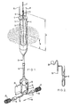
- the apparatus comprises an instrument 1 which is placed in the water, and a manometer 2.
- the instrument 1 has a substantially circular cylindrical (about a vertical axis), closed damping chamber 3 which isforplacing in the water so thatthe average water level is at about half its height.
- the damping chamber 3 has a screwed-on top cap 4 to which is fitted supporting or suspending means in the form of a suspension hook 5 on a threaded stud carrying a locking nut 6 which prevents unhooking.
- the hook 5 is hooked on to the bottom of a suspension tape 7, graduated at for instance 10 cm intervals.
- the top of the suspension tape 7 is fitted to a fixed position on the vessel, preferably at deck level.
- the cap 4 also carries a small cross-section vent 8 for venting gas from the damping chamber 3 and a rigid pipe or gas duct 9 to which is fitted a flexible plastics tube 10 connected to the manometer 2, e.g. at deck level or in the ship's office. If wave movement is excessive, the vent 8 can be extended upwards, for instance by a flexible plastics tube, to bring its upper end above the tops of the waves.
- the lower end or exit opening of the gas duct 9 is within the damping chamber 3; in theory it need only be in communication with the damping chamber 3, provided it is subjected to the pressure of the water in the damping chamber 3.
- a water duct 11 is furnished for providing a connection between the damping chamber 3 and the water in which the damping chamber 3 is immersed; the water duct 11 has an effective cross-sectional area which is much less than the horizontal cross-sectional area of the damping chamber 3.
- the water duct 11 admits water to the damping chamber 3 so that the water level in the damping chamber 3 is above the exit opening of the gas duct 9.
- the damping chamber 3 is vented by the vent 8
- the free water surface in the damping chamber 3 will, in still conditions, correspond to the water level of the surrounding water and, when there are waves, will correspond to the average level of the surrounding water, the effect of wave motion being dampened by the reduced cross-sectional area of the water duct 11.
- the water duct 11 projects downward below the damping chamber 3, being connected to the bottom of the damping chamber 3, and includes a substantially circular cylindrical (about a vertical axis) admission chamber or lower chamber 12 which is coaxial with the damping chamber 3.
- the admission chamber 12 is connected to the damping chamber 3 by one or more extension tubes 13 which ensure that the admission chamber 12 is maintained below water level, even when there is large wave motion.
- the extension tubes 13 can be screw-threaded, for easy assembly.
- the admission chamber 12 has a vertical separation member or plate 14 which extends for a substantial part of its height, dividing the respective part of the admission chamber 12 into an inlet zone 15 and an outlet zone 16.
- the damping chamber 3 is connected to the part of the admission chamber 12 above the separation plate 14; a water inlet 17 and a water outlet 18 lead to the bottoms of the inlet and outlet zones 15, 16 and open into the surrounding water at diametrically opposite positions. These positions are arranged to be upstream and downstream of the instrument 1 in the direction of current flow (indicated by the arrow 19) and face respectively upstream and downstream, so that water flows through the admission chamber 12 when there is a current (the separation plate 14 will be at right angles to the current).
- a vane or fixed rudder 20 is fixed to the admission chamber 12. In this way, the pressure effect of the incoming current is balanced by the suction effect of the outgoing current and the water level in the damping chamber 3 is more representative of the true water level.
- the water inlet and outlet 17, 18 are protected by fine strainers 21, 22, and exchangeable restrictor orifices 23, 24 are screwed in between the strainers 21, 22 and the remainder of the inlet or outlet 17, 18.
- the restrictor orifices 23, 24 have the same cross-section, so that the effective cross-sectional areas of the inlet and outlet 17, 18 are equal and are much smaller than the horizontal cross-sectional area of the admission chamber 12 and the flow cross-section in the admission chamber 12, thereby slowing down any flow in the admission chamber 12 and reducing any spurious pressure effects caused by flow.
- the orifices 23, 24 substantially determine the effective cross-sectional area of the whole water duct 11, and this is much less than the horizontal cross-sectional area of the damping chamber 3. If there is excessive wave motion, the restrictor orifices 23, 24 can be exchanged for smaller orifices.
- the manometer 2 is a normal water manometer, connected by means of a T to the flexible tube 10.
- a rubber bulb 25 with a one-way air valve is connected to the other limb of the T.
- a sample of sea water is taken at the operating level of the instrument 1 and is used to fill the manometer 2. Providing the temperature remains the same, this ensures that the apparatus is corrected for any differences in specific gravity of the water in which the vessel is floating.
- the instrument 1 is lowered to approximately the correct depth, and the height below deck level is noted from the graduations on the suspension tape 7.
- Air pressure is then applied by very light manual operation of the rubber bulb 25.
- the level difference B at the manometer 2 will be equal to the height B of the free water surface in the damping chamber 3 above the exit opening of the gas duct 9.
- the freeboard of the vessel will then be equal to the measurement on the suspension tape 7 plus a fixed dimension A less the measured height B.
- the gas duct 9 has an internal diameter of 3 mm
- the damping chamber 3 has an internal diameter of 49 mm
- the damping chamber 3 has a length (height) of 660 mm
- the extension tubes 13 have an internal diameter of 7 mm
- two alternative restrictor orifices 23, 24 are provided, having respective internal diameters of 2 mm and 4 mm.
- the horizontal cross-sectional area of the damping chamber 3 is about 75 times the effective cross-sectional area of the water duct 11.
- the horizontal cross-sectional area of the damping chamber 3 is about 300 times the effective cross-sectional area of the water duct 11.
Landscapes
- Chemical & Material Sciences (AREA)
- Engineering & Computer Science (AREA)
- Combustion & Propulsion (AREA)
- Mechanical Engineering (AREA)
- Ocean & Marine Engineering (AREA)
- Measuring Fluid Pressure (AREA)
- Measurement Of Levels Of Liquids Or Fluent Solid Materials (AREA)
Claims (13)
Applications Claiming Priority (2)
| Application Number | Priority Date | Filing Date | Title |
|---|---|---|---|
| GB838300332A GB8300332D0 (en) | 1983-01-07 | 1983-01-07 | Ships draft measuring apparatus |
| GB8300332 | 1983-01-07 |
Publications (3)
| Publication Number | Publication Date |
|---|---|
| EP0114089A2 EP0114089A2 (fr) | 1984-07-25 |
| EP0114089A3 EP0114089A3 (en) | 1984-08-15 |
| EP0114089B1 true EP0114089B1 (fr) | 1988-01-07 |
Family
ID=10536008
Family Applications (1)
| Application Number | Title | Priority Date | Filing Date |
|---|---|---|---|
| EP84300025A Expired EP0114089B1 (fr) | 1983-01-07 | 1984-01-04 | Mesure du tirant d'eau d'un navire |
Country Status (5)
| Country | Link |
|---|---|
| US (1) | US4534217A (fr) |
| EP (1) | EP0114089B1 (fr) |
| JP (1) | JPS59136621A (fr) |
| DE (1) | DE3468388D1 (fr) |
| GB (1) | GB8300332D0 (fr) |
Cited By (1)
| Publication number | Priority date | Publication date | Assignee | Title |
|---|---|---|---|---|
| CN105314078A (zh) * | 2015-09-24 | 2016-02-10 | 哈尔滨工程大学 | 一种起重船起重作业时的吃水快速计算方法 |
Families Citing this family (7)
| Publication number | Priority date | Publication date | Assignee | Title |
|---|---|---|---|---|
| BE1001711A3 (nl) * | 1988-01-15 | 1990-02-13 | Dimed N V | Inrichting voor het meten van de diepgang van vaartuigen. |
| US6836746B2 (en) | 2002-04-01 | 2004-12-28 | Control Stuff, Inc. | Method and apparatus for calculating the payload on a water-borne vessel |
| US20050188763A1 (en) * | 2004-02-26 | 2005-09-01 | Krejci John J. | Method and apparatus for measuring the draft of a vessel |
| US20090112510A1 (en) * | 2007-10-31 | 2009-04-30 | Crane John C | Method and system for continuously determining vessel draft and amount of cargo in a vessel undergoing loading |
| CN104925235B (zh) * | 2015-07-24 | 2017-12-29 | 武汉理工大学 | 船舶水尺观测装置 |
| CN112124510A (zh) * | 2020-09-24 | 2020-12-25 | 广船国际有限公司 | 一种船舶吃水的监测装置及监测方法 |
| CN114715345A (zh) * | 2022-04-12 | 2022-07-08 | 威海海洋职业学院 | 一种防止波浪影响的船舶吃水测量装置 |
Citations (1)
| Publication number | Priority date | Publication date | Assignee | Title |
|---|---|---|---|---|
| US2409310A (en) * | 1945-10-26 | 1946-10-15 | Glenn L Martin Co | Weight and balance indicator |
Family Cites Families (8)
| Publication number | Priority date | Publication date | Assignee | Title |
|---|---|---|---|---|
| FR466793A (fr) * | 1913-05-19 | 1914-05-23 | Harry Shawnee Parks | Indicateur pneumatique de profondeurs |
| GB189991A (en) * | 1921-11-29 | 1922-12-14 | William Alexander | Improved depth, draught and displacement indicator |
| GB227797A (en) * | 1924-01-18 | 1926-01-28 | Commanditaire Vennootschap Fro | Improvements in apparatus for indicating the draught of ships |
| GB939326A (en) * | 1961-07-27 | 1963-10-09 | Takashi Isobe | An apparatus for determining the weight of cargo on board a ship |
| NL6402719A (fr) * | 1963-03-16 | 1964-09-17 | ||
| US3396470A (en) * | 1967-07-26 | 1968-08-13 | Harold R. Wood | Apparatus for measuring freeboard in choppy water |
| US3548658A (en) * | 1969-02-18 | 1970-12-22 | Roland C Lawes | Draught gage |
| FR2250668A1 (en) * | 1973-11-08 | 1975-06-06 | Cermat | Installation for measuring a ship's draught - has water pressure transducers and a digital readout system |
-
1983
- 1983-01-07 GB GB838300332A patent/GB8300332D0/en active Pending
-
1984
- 1984-01-04 EP EP84300025A patent/EP0114089B1/fr not_active Expired
- 1984-01-04 DE DE8484300025T patent/DE3468388D1/de not_active Expired
- 1984-01-05 US US06/568,402 patent/US4534217A/en not_active Expired - Fee Related
- 1984-01-06 JP JP59000723A patent/JPS59136621A/ja active Pending
Patent Citations (1)
| Publication number | Priority date | Publication date | Assignee | Title |
|---|---|---|---|---|
| US2409310A (en) * | 1945-10-26 | 1946-10-15 | Glenn L Martin Co | Weight and balance indicator |
Cited By (1)
| Publication number | Priority date | Publication date | Assignee | Title |
|---|---|---|---|---|
| CN105314078A (zh) * | 2015-09-24 | 2016-02-10 | 哈尔滨工程大学 | 一种起重船起重作业时的吃水快速计算方法 |
Also Published As
| Publication number | Publication date |
|---|---|
| JPS59136621A (ja) | 1984-08-06 |
| GB8300332D0 (en) | 1983-02-09 |
| DE3468388D1 (en) | 1988-02-11 |
| EP0114089A3 (en) | 1984-08-15 |
| EP0114089A2 (fr) | 1984-07-25 |
| US4534217A (en) | 1985-08-13 |
Similar Documents
| Publication | Publication Date | Title |
|---|---|---|
| EP0114089B1 (fr) | Mesure du tirant d'eau d'un navire | |
| US4231313A (en) | Stabilizing system on a semi-submersible crane vessel | |
| EP3139177B1 (fr) | Loch électromagnétique amélioré à électrodes démontables | |
| CN101879936A (zh) | 船舶纵倾仪 | |
| NO149991B (no) | Innretning for oppsamling av olje | |
| NO782670L (no) | Apparat for aa detektere vaeskenivaaet i en tank | |
| US20050188763A1 (en) | Method and apparatus for measuring the draft of a vessel | |
| US3334608A (en) | Method and apparatus for establishing draft and trim of a vessel | |
| KR20120062093A (ko) | 선체의 흘수 계측용 장치 | |
| EP0244368A1 (fr) | Réservoirs ouverts longitudinaux pour la stabilisation de bateaux | |
| CN110641623B (zh) | 参数测量式浮标 | |
| US4554830A (en) | Level detection head for hydrostatic effect with protection | |
| US4676182A (en) | Suspension means for a mooring line | |
| US2678060A (en) | Float gauge | |
| KR101871103B1 (ko) | 해저케이블이 접속 가능한 다목적 해상플랫폼용 노매드 부이 | |
| CN206528601U (zh) | 高精度船舶吃水遥测装置 | |
| RU185214U1 (ru) | Устройство для подводного отбора пузырьков газа | |
| JPS6015285A (ja) | 海上浮体物に対する「ばら」物荷役量監視方法 | |
| JPS57101720A (en) | Flow meter in open ditch | |
| WO1986002328A1 (fr) | Procede et systeme de determination de la stabilite d'un corps flottant | |
| US3066531A (en) | Instrument for determining the elevation above water level | |
| US1131412A (en) | Pneumatic depth-indicator. | |
| CN220430455U (zh) | 一种观测船舶吃水位置的装置 | |
| CN223808298U (zh) | 一种潜入式液体密度检测装置 | |
| US5308272A (en) | Ascent rate indicator |
Legal Events
| Date | Code | Title | Description |
|---|---|---|---|
| PUAI | Public reference made under article 153(3) epc to a published international application that has entered the european phase |
Free format text: ORIGINAL CODE: 0009012 |
|
| PUAL | Search report despatched |
Free format text: ORIGINAL CODE: 0009013 |
|
| AK | Designated contracting states |
Designated state(s): BE DE FR GB IT NL |
|
| AK | Designated contracting states |
Designated state(s): BE DE FR GB IT NL |
|
| 17P | Request for examination filed |
Effective date: 19840917 |
|
| GRAA | (expected) grant |
Free format text: ORIGINAL CODE: 0009210 |
|
| AK | Designated contracting states |
Kind code of ref document: B1 Designated state(s): BE DE FR GB IT NL |
|
| PG25 | Lapsed in a contracting state [announced via postgrant information from national office to epo] |
Ref country code: NL Effective date: 19880107 Ref country code: IT Free format text: LAPSE BECAUSE OF FAILURE TO SUBMIT A TRANSLATION OF THE DESCRIPTION OR TO PAY THE FEE WITHIN THE PRESCRIBED TIME-LIMIT;WARNING: LAPSES OF ITALIAN PATENTS WITH EFFECTIVE DATE BEFORE 2007 MAY HAVE OCCURRED AT ANY TIME BEFORE 2007. THE CORRECT EFFECTIVE DATE MAY BE DIFFERENT FROM THE ONE RECORDED. Effective date: 19880107 Ref country code: FR Free format text: THE PATENT HAS BEEN ANNULLED BY A DECISION OF A NATIONAL AUTHORITY Effective date: 19880107 Ref country code: BE Effective date: 19880107 |
|
| REF | Corresponds to: |
Ref document number: 3468388 Country of ref document: DE Date of ref document: 19880211 |
|
| EN | Fr: translation not filed | ||
| NLV1 | Nl: lapsed or annulled due to failure to fulfill the requirements of art. 29p and 29m of the patents act | ||
| PLBE | No opposition filed within time limit |
Free format text: ORIGINAL CODE: 0009261 |
|
| STAA | Information on the status of an ep patent application or granted ep patent |
Free format text: STATUS: NO OPPOSITION FILED WITHIN TIME LIMIT |
|
| 26N | No opposition filed | ||
| PGFP | Annual fee paid to national office [announced via postgrant information from national office to epo] |
Ref country code: GB Payment date: 19891231 Year of fee payment: 7 |
|
| PGFP | Annual fee paid to national office [announced via postgrant information from national office to epo] |
Ref country code: DE Payment date: 19900131 Year of fee payment: 7 |
|
| PG25 | Lapsed in a contracting state [announced via postgrant information from national office to epo] |
Ref country code: GB Effective date: 19910104 |
|
| GBPC | Gb: european patent ceased through non-payment of renewal fee | ||
| PG25 | Lapsed in a contracting state [announced via postgrant information from national office to epo] |
Ref country code: DE Effective date: 19911001 |