EP0114178A1 - Apparat zur Luftreinigung - Google Patents
Apparat zur Luftreinigung Download PDFInfo
- Publication number
- EP0114178A1 EP0114178A1 EP83106121A EP83106121A EP0114178A1 EP 0114178 A1 EP0114178 A1 EP 0114178A1 EP 83106121 A EP83106121 A EP 83106121A EP 83106121 A EP83106121 A EP 83106121A EP 0114178 A1 EP0114178 A1 EP 0114178A1
- Authority
- EP
- European Patent Office
- Prior art keywords
- electrodes
- dust collecting
- ionizing wires
- wires
- panel electrodes
- Prior art date
- Legal status (The legal status is an assumption and is not a legal conclusion. Google has not performed a legal analysis and makes no representation as to the accuracy of the status listed.)
- Granted
Links
- 238000004140 cleaning Methods 0.000 title claims abstract description 26
- 239000000428 dust Substances 0.000 claims abstract description 40
- CBENFWSGALASAD-UHFFFAOYSA-N Ozone Chemical compound [O-][O+]=O CBENFWSGALASAD-UHFFFAOYSA-N 0.000 claims abstract description 31
- 238000004519 manufacturing process Methods 0.000 claims description 5
- 239000002245 particle Substances 0.000 abstract description 14
- 239000012535 impurity Substances 0.000 abstract description 7
- 230000000149 penetrating effect Effects 0.000 abstract 1
- 238000007747 plating Methods 0.000 description 7
- 230000005684 electric field Effects 0.000 description 6
- 150000002500 ions Chemical class 0.000 description 6
- 239000003245 coal Substances 0.000 description 5
- 238000000354 decomposition reaction Methods 0.000 description 5
- 229910000510 noble metal Inorganic materials 0.000 description 5
- BQCADISMDOOEFD-UHFFFAOYSA-N Silver Chemical compound [Ag] BQCADISMDOOEFD-UHFFFAOYSA-N 0.000 description 4
- 239000007789 gas Substances 0.000 description 4
- 229910052751 metal Inorganic materials 0.000 description 4
- 239000002184 metal Substances 0.000 description 4
- 229910052709 silver Inorganic materials 0.000 description 4
- 239000004332 silver Substances 0.000 description 4
- 238000010586 diagram Methods 0.000 description 3
- 230000007935 neutral effect Effects 0.000 description 3
- 238000013459 approach Methods 0.000 description 2
- 239000010419 fine particle Substances 0.000 description 2
- PCHJSUWPFVWCPO-UHFFFAOYSA-N gold Chemical compound [Au] PCHJSUWPFVWCPO-UHFFFAOYSA-N 0.000 description 2
- 229910052737 gold Inorganic materials 0.000 description 2
- 239000010931 gold Substances 0.000 description 2
- 238000012986 modification Methods 0.000 description 2
- 230000004048 modification Effects 0.000 description 2
- BASFCYQUMIYNBI-UHFFFAOYSA-N platinum Chemical compound [Pt] BASFCYQUMIYNBI-UHFFFAOYSA-N 0.000 description 2
- 229910001369 Brass Inorganic materials 0.000 description 1
- 229910052782 aluminium Inorganic materials 0.000 description 1
- XAGFODPZIPBFFR-UHFFFAOYSA-N aluminium Chemical compound [Al] XAGFODPZIPBFFR-UHFFFAOYSA-N 0.000 description 1
- QVGXLLKOCUKJST-UHFFFAOYSA-N atomic oxygen Chemical compound [O] QVGXLLKOCUKJST-UHFFFAOYSA-N 0.000 description 1
- 239000010951 brass Substances 0.000 description 1
- 229910052802 copper Inorganic materials 0.000 description 1
- 239000010949 copper Substances 0.000 description 1
- 230000007423 decrease Effects 0.000 description 1
- 230000007547 defect Effects 0.000 description 1
- 230000002708 enhancing effect Effects 0.000 description 1
- 238000003780 insertion Methods 0.000 description 1
- 230000037431 insertion Effects 0.000 description 1
- WABPQHHGFIMREM-UHFFFAOYSA-N lead(0) Chemical compound [Pb] WABPQHHGFIMREM-UHFFFAOYSA-N 0.000 description 1
- 239000001301 oxygen Substances 0.000 description 1
- 229910052760 oxygen Inorganic materials 0.000 description 1
- 230000002093 peripheral effect Effects 0.000 description 1
- 229910052697 platinum Inorganic materials 0.000 description 1
- 230000000750 progressive effect Effects 0.000 description 1
- 230000001105 regulatory effect Effects 0.000 description 1
- 239000000758 substrate Substances 0.000 description 1
- WFKWXMTUELFFGS-UHFFFAOYSA-N tungsten Chemical compound [W] WFKWXMTUELFFGS-UHFFFAOYSA-N 0.000 description 1
- 229910052721 tungsten Inorganic materials 0.000 description 1
- 239000010937 tungsten Substances 0.000 description 1
- 230000003313 weakening effect Effects 0.000 description 1
Images




Classifications
-
- B—PERFORMING OPERATIONS; TRANSPORTING
- B03—SEPARATION OF SOLID MATERIALS USING LIQUIDS OR USING PNEUMATIC TABLES OR JIGS; MAGNETIC OR ELECTROSTATIC SEPARATION OF SOLID MATERIALS FROM SOLID MATERIALS OR FLUIDS; SEPARATION BY HIGH-VOLTAGE ELECTRIC FIELDS
- B03C—MAGNETIC OR ELECTROSTATIC SEPARATION OF SOLID MATERIALS FROM SOLID MATERIALS OR FLUIDS; SEPARATION BY HIGH-VOLTAGE ELECTRIC FIELDS
- B03C3/00—Separating dispersed particles from gases or vapour, e.g. air, by electrostatic effect
- B03C3/34—Constructional details or accessories or operation thereof
- B03C3/40—Electrode constructions
- B03C3/45—Collecting-electrodes
-
- B—PERFORMING OPERATIONS; TRANSPORTING
- B03—SEPARATION OF SOLID MATERIALS USING LIQUIDS OR USING PNEUMATIC TABLES OR JIGS; MAGNETIC OR ELECTROSTATIC SEPARATION OF SOLID MATERIALS FROM SOLID MATERIALS OR FLUIDS; SEPARATION BY HIGH-VOLTAGE ELECTRIC FIELDS
- B03C—MAGNETIC OR ELECTROSTATIC SEPARATION OF SOLID MATERIALS FROM SOLID MATERIALS OR FLUIDS; SEPARATION BY HIGH-VOLTAGE ELECTRIC FIELDS
- B03C3/00—Separating dispersed particles from gases or vapour, e.g. air, by electrostatic effect
- B03C3/02—Plant or installations having external electricity supply
- B03C3/04—Plant or installations having external electricity supply dry type
- B03C3/14—Plant or installations having external electricity supply dry type characterised by the additional use of mechanical effects, e.g. gravity
-
- B—PERFORMING OPERATIONS; TRANSPORTING
- B03—SEPARATION OF SOLID MATERIALS USING LIQUIDS OR USING PNEUMATIC TABLES OR JIGS; MAGNETIC OR ELECTROSTATIC SEPARATION OF SOLID MATERIALS FROM SOLID MATERIALS OR FLUIDS; SEPARATION BY HIGH-VOLTAGE ELECTRIC FIELDS
- B03C—MAGNETIC OR ELECTROSTATIC SEPARATION OF SOLID MATERIALS FROM SOLID MATERIALS OR FLUIDS; SEPARATION BY HIGH-VOLTAGE ELECTRIC FIELDS
- B03C3/00—Separating dispersed particles from gases or vapour, e.g. air, by electrostatic effect
- B03C3/02—Plant or installations having external electricity supply
- B03C3/04—Plant or installations having external electricity supply dry type
- B03C3/12—Plant or installations having external electricity supply dry type characterised by separation of ionising and collecting stations
-
- B—PERFORMING OPERATIONS; TRANSPORTING
- B03—SEPARATION OF SOLID MATERIALS USING LIQUIDS OR USING PNEUMATIC TABLES OR JIGS; MAGNETIC OR ELECTROSTATIC SEPARATION OF SOLID MATERIALS FROM SOLID MATERIALS OR FLUIDS; SEPARATION BY HIGH-VOLTAGE ELECTRIC FIELDS
- B03C—MAGNETIC OR ELECTROSTATIC SEPARATION OF SOLID MATERIALS FROM SOLID MATERIALS OR FLUIDS; SEPARATION BY HIGH-VOLTAGE ELECTRIC FIELDS
- B03C3/00—Separating dispersed particles from gases or vapour, e.g. air, by electrostatic effect
- B03C3/34—Constructional details or accessories or operation thereof
- B03C3/40—Electrode constructions
Definitions
- This invention relates to an air cleaning apparatus.
- a conventional air cleaner which is, for example, disclosed in Japanese Patent No. 996,051 is known. More particularly, a conventional air cleaner has, as shown in Fig. 1, a plurality of dust collecting electrodes 1 formed of aluminum and corresponding electrodes 2, alternately arranged oppositely to each other at an interval or gap such as approx. 10 mm to become an air flow passage, and ionizing wires 3 installed at the outside isolated at a distance r from the line connecting the ends of the respective electrodes 1 on an extension line from the electrodes 2. The distance r is defined to approx. 20 mm.
- the wires 3 and the electrodes are commonly connected as to have positive polarity, the electrodes 1 have negative polarity, and a voltage of approx.
- the volume and the cleaning efficiency of a cleaning chamber to be cleaned by an air cleaner are different depending upon the purpose of using the cleaning chamber.
- the air cleaner requires the corresponding performance.
- the velocity of the air stream to be produced is defined substantially to a predetermined value when the voltage of the power source is defined to a constant value. Therefore, the conventional air cleaner has drawbacks so as not to sufficiently respond to the above-described desires.
- a cleaning apparatus which comprises a plurality of dust collecting panel electrodes and corresponding panel electrodes, arranged oppositely to each other via a predetermined interval to become air flow passages in a casing having air flow inlet and outlet, and a number of ionizing wires installed at a predetermined distance from the end of the dust collecting panel electrodes substantially on extension lines from the respective corresponding electrodes at the position out of the interval.
- the dust collecting panel electrodes, and the corresponding panel electrodes and the ionizing wires are provided at a narrow interval so that the corresponding panel electrodes and the ionizing wires have equal polarity as the dust collecting panel electrodes, the voltage applied between the dust collecting panel electrodes and the corresponding panel electrodes is set to substantially one-half of that applied between the dust collecting panel electrodes and the ionizing wires, and the length of the interval between the dust collecting panel electrodes and the corresponding panel electrodes is so as to produce a predetermined potential gradient in response to the applied voltage value.
- ozone decomposition accelerating noble metal plating layer is coated on each of the dust collecting panel electrodes and the corresponding panel electrodes, and ozone decomposing filter means formed of activated coal is arranged at the air flow outlet.
- This air cleaning apparatus of the invention can thus improve the dust collecting efficiency to a sufficient degree in practical use and can reduce the ozone flow rate.
- an air cleaning apparatus which further comprises other second ionizing wires installed at a predetermined distance from the first ionizing wires substantially on extension lines of the respective dust collecting panel electrodes at the position further outer than the arranging position of the first ionizing wires, thereby generating a corona discharge between the first and the second ionizing wires to accelerate the produced air stream.
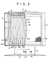
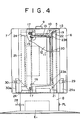
- FIGs. 2 to 6 show a typical embodiment of an air cleaning apparatus according to the present invention.
- reference numeral 5 designates a casing, in which inlet and outlet side mask frames 6 and 7 respectively having mask nets 6a and 7a are detachably mounted to become air flow inlet and outlet at left and right sides.
- a stand 8 is mounted at the lower portion of the casing 5, and a handle 9 is mounted on the top of the casing 5.
- Said casing 5 has therein units which respectively have ionizing function, dust collecting function and ozone decomposing function, and a containing frame 10 for holding the units. More particularly, as shown in Fig. 3, a unit containing frame 10 is fixedly secured substantially to the center of the casing 5, and a dust collecting unit frame 13 is detachably mounted on the frame 10.
- the frame 13 has a plurality of dust collecting panel electrodes 11 and corresponding panel electrodes 12 alternately arranged oppositely to each other at a predetermined interval 14.
- the interval or air gaps 14 form air flow passages, which are maintained, for example, at approx. 5 mm.
- the electrodes 11 and 12 are formed of substrates such as metal plates made of brass or-copper, and are treated with ozone decomposition accelerating silver plating layers.
- the metal for accelerating the ozone decomposition may include, for example, not only the silver, but noble metals such as gold, or platinum.
- Each of the electrodes 12 is formed narrower in width and shorter in length than the electrode 11, and is, as shown in Fig. 3, disposed at the edge lla inside the interval by a predetermined distance from the line for connecting the edges lla of the electrodes 11.
- a pair of terminal boards 15- and 16 are bonded, as shown in Fig.
- the electrodes 11 are commonly connected to the upper board 15, and the electrodes 12 are commonly connected to the lower board 16.
- 16a designates a plug socket
- 16b designates a terminal receptacle
- the other board 15 also has similarly a plug socket and a terminal receptacle (not shown).
- the electrodes 11 and 12 are respectively connected to a power source El Lhrough the plug socket and the terminal receptacle as will be described with reference to Fig. 6.
- the frame 13 is formed, as shown in Fig. 3, in tapered surfaces on the four outer peripheral surfaces.
- the inner surface of the frame 10 are also formed in the tapered surface corresponding to the tapered surfaces of the frame 13, which is detachably from the rear side to the frame 10. 17 and 17 depict night latches, and the frame 13 is anchored by the latches 17 at the inserted position.
- the electrodes 11 and 12 are detachably provided integrally to the casing 5 by the insertion or removal of the frame 13.
- the frame 10 is slightly expanded at the front side.
- An ionizing unit frame 18 formed of metal is engaged with the expanded portion (Figs. 3 and 4).
- Reference numeral 19 illustrates an ionizing unit retaining frame, and the frame 18 is secured fixedly by the frame 19 at the engaged position.
- Ionizing wires 20 are installed between the upper and lower beams at the frame 18.
- the wires 20 are formed of tungsten wires having approx. 1 mil of thickness, and are treated with noble metal plating layer of gold similarly to the above.
- Each wire 20 has a coil spring 21 elastically extended at the lower portion thereof. The lower end of each spring 21 is engaged with a hole 18a perforated at the frame 18, and the upper end of each wire 20 is engaged fixedly by a screw 22 with the frame 18.
- the wires 20 are defined at positions isolated at a predetermined distance such as, for example, approx. 20 mm from a line for connecting the front edges lla of the electrodes 11 on the front extension line of the respective electrodes 12.
- the position of the wire can be readily defined by elastically engaging the spring 21.
- Each wire 20 is connected to the power source E 1 via a lead wire (not shown) led from the frame 18.
- Shielding plates 23a and. 23b formed of plastic for preventing ozone stand in a predetermined height between the vicinities of the installing ends of the wires 20, the electrodes 11 and 12.
- filter frame mounts 24 are extended from four rear corners of the frame 10, and an ozone decomposing filter 25 is enaged with the mounts 24.
- the filter 25 is formed of activated coal, which is pulverized in mesh of approx. 12 cells/square inch, thereby enhancing the ozone decomposing function.
- Fig. 6 snows the connecting state of the electrodes 11 and 12 and the power source E 1 , and the electrodes 11 are connected to a negative terminal 26 in negative polarity.
- the wires 20 and the electrodes 12 are connected in positive polarity, and the wires 20 are connected through a discharge current regulating resistor R to the positive terminal 26a, and the electrodes 12 are connected to an intermediate terminal 26b of 1/2 voltage point.
- the voltage value of the terminal 26a is, for example, 15 kV.
- the length of the interval between the electrodes 12 and 11 is defined to approx. 5 mm to maintain a predetermined potential gradient, approx. 1.5 kV/mm corresponding to 1/2 of the applied voltage value.
- reference numeral 27 designates a power switch, 28 a power cord, PL a pilot lamp, 29 and 30 safety limit switches, and 29a and 30a limit switch mounting brackets.
- the switches 29 and 30 are composed of normally closed contacts connected in series with the switch 27 and switched to OFF when the inlet or outlet side mask 6 or 7 is removed, thereby preventing the high voltage from contacting a hand.
- the air cleaning apparatus is installed at a predetermined position in a room.
- the numerous ions moved by the corona discharge to the electrodes 11 side their kinetic energy is applied to the neutral gas molecules, a type of air stream is generated in this manner, thereby producing an air stream flowing toward the intervalsl4 at a predetermined velocity such as approx. 60 m/min.
- impurity particles in the air are charged in one ions and are collected the electrodes 11.
- the intervals 14 are narrow such as 5 mm. Accordingly, the impurity particle collecting probability in the course of passing the intervals 14 is increased, thereby effectively performing the dust collection.
- the measured example of the efficiency is shown as below:
- the dust collecting efficiency of the conventional air cleaner of electrostatic type is normally approx. 50%.
- a large quantity of ozone is produced by- the above corona discharge with the high electric field.
- the ozone is contacted by the silver plating layer coated on the electrodes 11 and 12 in the course of passing the intervals 14 and is decomposed to oxygen molecules. Since the electric field is concentrated in the vicinity of the ends of the wires 20, the quantity of produced ozone in this part tends to increase as compared with the other part. Since the plates 23a and 23b are however located on this part, the corona discharge is disturbed by the plates, thereby suppressing the production of the ozone in this part. The quantity of the produced ozone can be reduced to approx. 20 pp b , wh i ch is approx.
- the ozone decomposition of the silver plating layer and the ozone production preventing operation of the plates 23a and 23b is further decomposed in contact with the ozone decomposing filter 25 of activated coal in the course of flowing out from the outlet side. Since the filter 25 is formed in the predetermined mesh of 12 cells/square inch, the flowing ozone can be progressively decomposed effectively in contact with the surface of the activated coal, and can be further reduced.
- The.degree of decomposing the ozone by the filter 25 depends upon the quantity of the ozone flowed to the filter, but 25 to 40 % of the ozone is decomposed by the filter. Since the filter 25 is inactivated as it is used, it is necessary to suitably exchange the filter, but since the filter 25 in this invention is formed of activated coal, its lifetime is maintained over one year.
- the noble metal plating layers coated on the plates 23a and 23b and the electrodes 11 and 12 as well as the filter 15 cooperate to suppress, the production of ozone or to effectively decompose the ozone so as to remarkably reduce the ozone less than the stipulated quantity so as not to produce a defect on human body.
- the impurity particles from the air are accumulated on the electrodes 11 due to the above described effective dust collecting operation. Accordingly, it is necessary to clean the electrodes 11. At this time, the electrodes 11 and 12 are removed from the casing 5 together with the frame 13 and are cleaned.
- FIGs. 7 to 9 other preferred embodiments of the air cleaning apparatus according to the invention are shown.
- the members or those equal or equivalent to those members are designated by the same reference numerals in Figs. 2 to 8 and will not accordingly be described but will be omitted.
- other second ionizing wires 20b are installed at a 5 predetermined distance from the first ionizing wires 20a substantially on extension lines from the respective electrodes 11 at positions further out than the arranging positions of the wires 20a, and corona discharges are also produced even between the wires 20a and the wires 20b.
- First and second ionizing unit frames 31a and 31b formed of metal are, for example, engaged fixedly at a predetermined interval such as approx. 13 mm at the inlet side expanded part of the unit containing. frame 10.
- the first ionizing wires 20a are installed between the upper and the lower beams in the frame 31a
- the second ionizing wires 20b are installed between the upper and the lower beams in the second ionizing unit frame 31b.
- Both the wires 20a and 20b - are constructed similarly to those in the first embodiment at the points that the ozone decomposition accelerating noble metal plating layers are coated and that the coil springs are mounted at the lower parts.
- the first ionizing wires 20a are defined at positions isolated at a predetermined distance such as, for example, 13 mm from the line connecting the edges lla of the respective wires 11, on the front extension lines from the respective electrodes 12.
- the second ionizing wires 20b are installed at positions isolated at a predetermined distance such as, for example, 13 mm from the line connecting the respective wires 20a on the extension lines from the. respective electrodes 11,at positions further out than the arranging positions of the wires 20a.
- the first and second.wires 20a and 20b are arranged in two stages. When the wires 20a and 20b are elastically installed by the coil spring, the wires can be readily defined at the position to be installed.
- the wires 20a and 20b are respectively connected to the terminals of a power source E 2 which will be described later, via lead wires (not shown) led from the frames 31a and 31b.
- Fig. 8 shows the connecting states of the electrodes 11 and 12, the wires 20a and 20b and the power source E 2 .
- the wires 20a are connected to a 0 volt terminal 32a
- the wires 20b are connected to positive V terminal 32b
- the electrodes 11 are connected to negative V terminal 32c
- the electrodes 12 are connected to negative 1/2V terminal 32d.
- a predetermined discharge voltage of 12.5 kV is applied between the electrodes 11 and the wires 20a and between the wires 20a and the wires 20b.
- the length of the interval between the electrodes 11 and 12 is defined to slightly longer than 4 mm corresponding to the applied voltage value of the 1/2 so as to set a predetermined potential gradient of approx. 1.5 kV/mm.
- the initial flow produced by the corona discharge of the first stage between the Wires 20a and 20b is accelerated by the corona discharge of the second stage between the wires 20a and the electrodes 11, performing the velocity of the air stream to reach approx. 85 m/min.
- This velocity is accelerated by approx. 40% as compared with that in the first embodiment.
- impurity particles in the air are charged to one ions and are collected by the electrodes 11.
- a voltage of 6.25 kV is applied through the intervals between the electrodes 11 and 12. Accordingly, the remaining particles not collected by the corona discharge of the particles in the air are attracted onto the electrodes 11 by the electric field produced in this manner and are collected.
- This particle collecting operation is formed in a narrow width such as, for example, approx. 4 mm in the length of the intervals. Even if the velocity is accelerated, this operation can be remarkably effectively performed.
- a modified example of the panel electrode arranging state in the above second embodiment is shown.
- the arrangement of the corresponding panel electrodes is omitted as compared with that in Figs. 7 and 8.
- the velocity of the air stream flowing in the intervals, and hence the point of air flow rate can be further accelerated.
Landscapes
- Electrostatic Separation (AREA)
Applications Claiming Priority (4)
| Application Number | Priority Date | Filing Date | Title |
|---|---|---|---|
| JP228284/82 | 1982-12-30 | ||
| JP57228284A JPS59123544A (ja) | 1982-12-30 | 1982-12-30 | 空気浄化装置 |
| JP24831/83 | 1983-02-18 | ||
| JP58024831A JPS6044018B2 (ja) | 1983-02-18 | 1983-02-18 | 空気浄化装置 |
Publications (2)
| Publication Number | Publication Date |
|---|---|
| EP0114178A1 true EP0114178A1 (de) | 1984-08-01 |
| EP0114178B1 EP0114178B1 (de) | 1986-11-05 |
Family
ID=26362400
Family Applications (1)
| Application Number | Title | Priority Date | Filing Date |
|---|---|---|---|
| EP83106121A Expired EP0114178B1 (de) | 1982-12-30 | 1983-06-22 | Apparat zur Luftreinigung |
Country Status (5)
| Country | Link |
|---|---|
| US (1) | US4516991A (de) |
| EP (1) | EP0114178B1 (de) |
| KR (1) | KR850000260A (de) |
| CA (1) | CA1204391A (de) |
| DE (1) | DE3367337D1 (de) |
Cited By (2)
| Publication number | Priority date | Publication date | Assignee | Title |
|---|---|---|---|---|
| WO1999048611A1 (en) * | 1998-03-23 | 1999-09-30 | Koninklijke Philips Electronics N.V. | Air cleaner |
| RU2453377C1 (ru) * | 2011-02-24 | 2012-06-20 | Юрий Алексеевич Криштафович | Электрический очиститель воздуха |
Families Citing this family (76)
| Publication number | Priority date | Publication date | Assignee | Title |
|---|---|---|---|---|
| US4689056A (en) * | 1983-11-23 | 1987-08-25 | Nippon Soken, Inc. | Air cleaner using ionic wind |
| JPS60132661A (ja) * | 1983-12-20 | 1985-07-15 | Nippon Soken Inc | 空気清浄器 |
| GB2154156B (en) * | 1984-01-24 | 1987-10-21 | Nippon Light Metal Co | Electrostatic air cleaner |
| US4772297A (en) * | 1985-09-20 | 1988-09-20 | Kyowa Seiko Co., Ltd. | Air cleaner |
| US4666474A (en) * | 1986-08-11 | 1987-05-19 | Amax Inc. | Electrostatic precipitators |
| JPH02172545A (ja) * | 1988-12-23 | 1990-07-04 | Hiroaki Kanazawa | 空気清浄機 |
| KR910002599Y1 (ko) * | 1989-06-15 | 1991-04-22 | 삼성전자 주식회사 | 공기청정기 이온회선의 전열발생 구조 |
| JPH03115050U (de) * | 1990-03-06 | 1991-11-27 | ||
| US5302190A (en) * | 1992-06-08 | 1994-04-12 | Trion, Inc. | Electrostatic air cleaner with negative polarity power and method of using same |
| US5707428A (en) * | 1995-08-07 | 1998-01-13 | Environmental Elements Corp. | Laminar flow electrostatic precipitation system |
| US5656063A (en) * | 1996-01-29 | 1997-08-12 | Airlux Electrical Co., Ltd. | Air cleaner with separate ozone and ionizer outputs and method of purifying air |
| US5785932A (en) * | 1996-02-22 | 1998-07-28 | Environmental Elements Corp. | Catalytic reactor for oxidizing mercury vapor |
| US6504308B1 (en) * | 1998-10-16 | 2003-01-07 | Kronos Air Technologies, Inc. | Electrostatic fluid accelerator |
| US6176977B1 (en) | 1998-11-05 | 2001-01-23 | Sharper Image Corporation | Electro-kinetic air transporter-conditioner |
| US20020155041A1 (en) * | 1998-11-05 | 2002-10-24 | Mckinney Edward C. | Electro-kinetic air transporter-conditioner with non-equidistant collector electrodes |
| US6632407B1 (en) * | 1998-11-05 | 2003-10-14 | Sharper Image Corporation | Personal electro-kinetic air transporter-conditioner |
| US20030206837A1 (en) | 1998-11-05 | 2003-11-06 | Taylor Charles E. | Electro-kinetic air transporter and conditioner device with enhanced maintenance features and enhanced anti-microorganism capability |
| US7220295B2 (en) | 2003-05-14 | 2007-05-22 | Sharper Image Corporation | Electrode self-cleaning mechanisms with anti-arc guard for electro-kinetic air transporter-conditioner devices |
| US7695690B2 (en) * | 1998-11-05 | 2010-04-13 | Tessera, Inc. | Air treatment apparatus having multiple downstream electrodes |
| US20020146356A1 (en) * | 1998-11-05 | 2002-10-10 | Sinaiko Robert J. | Dual input and outlet electrostatic air transporter-conditioner |
| US20050210902A1 (en) | 2004-02-18 | 2005-09-29 | Sharper Image Corporation | Electro-kinetic air transporter and/or conditioner devices with features for cleaning emitter electrodes |
| US6911186B2 (en) * | 1998-11-05 | 2005-06-28 | Sharper Image Corporation | Electro-kinetic air transporter and conditioner device with enhanced housing configuration and enhanced anti-microorganism capability |
| US7318856B2 (en) | 1998-11-05 | 2008-01-15 | Sharper Image Corporation | Air treatment apparatus having an electrode extending along an axis which is substantially perpendicular to an air flow path |
| US6974560B2 (en) * | 1998-11-05 | 2005-12-13 | Sharper Image Corporation | Electro-kinetic air transporter and conditioner device with enhanced anti-microorganism capability |
| US6544485B1 (en) | 2001-01-29 | 2003-04-08 | Sharper Image Corporation | Electro-kinetic device with enhanced anti-microorganism capability |
| US6350417B1 (en) * | 1998-11-05 | 2002-02-26 | Sharper Image Corporation | Electrode self-cleaning mechanism for electro-kinetic air transporter-conditioner devices |
| JP3496588B2 (ja) | 1999-09-14 | 2004-02-16 | ダイキン工業株式会社 | 空気清浄機およびそのイオン化ユニット |
| RU2198735C2 (ru) * | 2001-03-20 | 2003-02-20 | Карпенко Сергей Иванович | Многосекционный электрофильтр |
| US6749667B2 (en) * | 2002-06-20 | 2004-06-15 | Sharper Image Corporation | Electrode self-cleaning mechanism for electro-kinetic air transporter-conditioner devices |
| US7056370B2 (en) * | 2002-06-20 | 2006-06-06 | Sharper Image Corporation | Electrode self-cleaning mechanism for air conditioner devices |
| US6937455B2 (en) | 2002-07-03 | 2005-08-30 | Kronos Advanced Technologies, Inc. | Spark management method and device |
| US7053565B2 (en) | 2002-07-03 | 2006-05-30 | Kronos Advanced Technologies, Inc. | Electrostatic fluid accelerator for and a method of controlling fluid flow |
| US7405672B2 (en) | 2003-04-09 | 2008-07-29 | Sharper Image Corp. | Air treatment device having a sensor |
| US6984987B2 (en) * | 2003-06-12 | 2006-01-10 | Sharper Image Corporation | Electro-kinetic air transporter and conditioner devices with enhanced arching detection and suppression features |
| US7724492B2 (en) | 2003-09-05 | 2010-05-25 | Tessera, Inc. | Emitter electrode having a strip shape |
| US20050051420A1 (en) | 2003-09-05 | 2005-03-10 | Sharper Image Corporation | Electro-kinetic air transporter and conditioner devices with insulated driver electrodes |
| US7077890B2 (en) | 2003-09-05 | 2006-07-18 | Sharper Image Corporation | Electrostatic precipitators with insulated driver electrodes |
| US7906080B1 (en) | 2003-09-05 | 2011-03-15 | Sharper Image Acquisition Llc | Air treatment apparatus having a liquid holder and a bipolar ionization device |
| US7517503B2 (en) | 2004-03-02 | 2009-04-14 | Sharper Image Acquisition Llc | Electro-kinetic air transporter and conditioner devices including pin-ring electrode configurations with driver electrode |
| JP4148865B2 (ja) * | 2003-09-26 | 2008-09-10 | 三洋電機株式会社 | 投写型映像表示装置 |
| US20050082160A1 (en) * | 2003-10-15 | 2005-04-21 | Sharper Image Corporation | Electro-kinetic air transporter and conditioner devices with a mesh collector electrode |
| US7767169B2 (en) | 2003-12-11 | 2010-08-03 | Sharper Image Acquisition Llc | Electro-kinetic air transporter-conditioner system and method to oxidize volatile organic compounds |
| US20050146712A1 (en) * | 2003-12-24 | 2005-07-07 | Lynx Photonics Networks Inc. | Circuit, system and method for optical switch status monitoring |
| US7638104B2 (en) | 2004-03-02 | 2009-12-29 | Sharper Image Acquisition Llc | Air conditioner device including pin-ring electrode configurations with driver electrode |
| JP2005275200A (ja) * | 2004-03-26 | 2005-10-06 | Sanyo Electric Co Ltd | 投写型映像表示装置 |
| US7285155B2 (en) | 2004-07-23 | 2007-10-23 | Taylor Charles E | Air conditioner device with enhanced ion output production features |
| US20060016333A1 (en) | 2004-07-23 | 2006-01-26 | Sharper Image Corporation | Air conditioner device with removable driver electrodes |
| US7311762B2 (en) | 2004-07-23 | 2007-12-25 | Sharper Image Corporation | Air conditioner device with a removable driver electrode |
| US7241330B2 (en) * | 2004-10-25 | 2007-07-10 | Oreck Holdings, Llc | Air cleaner electrostatic precipitator cell |
| US7713330B2 (en) * | 2004-12-22 | 2010-05-11 | Oreck Holdings, Llc | Tower ionizer air cleaner |
| US7297182B2 (en) * | 2005-03-02 | 2007-11-20 | Eisenmann Corporation | Wet electrostatic precipitator for treating oxidized biomass effluent |
| WO2006094174A2 (en) * | 2005-03-02 | 2006-09-08 | Eisenmann Corporation | Dual flow wet electrostatic precipitator |
| WO2007008587A2 (en) * | 2005-07-08 | 2007-01-18 | Eisenmann Corporation | Method and apparatus for particulate removal and undesirable vapor scrubbing from a moving gas stream |
| WO2007067626A2 (en) * | 2005-12-06 | 2007-06-14 | Eisenmann Corporation | Wet electrostatic liquid film oxidizing reactor apparatus and method for removal of nox, sox, mercury, acid droplets, heavy metals and ash particles from a moving gas |
| US7794518B2 (en) * | 2006-02-28 | 2010-09-14 | Oreck Holdings, Llc | Filter system for an air cleaner |
| US7833322B2 (en) | 2006-02-28 | 2010-11-16 | Sharper Image Acquisition Llc | Air treatment apparatus having a voltage control device responsive to current sensing |
| US7481870B2 (en) * | 2006-04-18 | 2009-01-27 | Oreck Holdings, Llc | Electrode wire for an electrostatic precipitator |
| US7276106B1 (en) | 2006-04-18 | 2007-10-02 | Oreck Holdings Llc | Electrode wire retaining member for an electrostatic precipitator |
| US7306655B2 (en) * | 2006-04-18 | 2007-12-11 | Oreck Holdings, Llc | Corona ground element |
| US7306648B2 (en) * | 2006-04-18 | 2007-12-11 | Oreck Holdings, Llc | Retainer for use with a corona ground element of an electrostatic precipitator |
| US7291206B1 (en) * | 2006-04-18 | 2007-11-06 | Oreck Holdings, Llc | Pre-ionizer for use with an electrostatic precipitator |
| US7597749B2 (en) * | 2006-07-18 | 2009-10-06 | Oreck Holdings, Llc | Frame for electrostatic precipitator cell |
| ES2301414B1 (es) * | 2006-12-11 | 2009-03-16 | Bsh Electrodomesticos España, S.A. | Dispositivo y proceso para el limpiado de un medio gaseoso contaminado con particulas. |
| US7815720B2 (en) | 2006-12-27 | 2010-10-19 | Strionair, Inc. | Dual-filter electrically enhanced air-filtration apparatus and method |
| US8106367B2 (en) * | 2009-12-30 | 2012-01-31 | Filt Air Ltd. | Method and ionizer for bipolar ion generation |
| US20150343454A1 (en) * | 2014-06-03 | 2015-12-03 | Restless Noggins Design, Llc | Charged filtration system |
| CN105797853B (zh) * | 2016-06-08 | 2018-03-27 | 佛山市顺德区拓维电器有限公司 | 一种高效吸附空气净化装置及空气净化器 |
| US10882053B2 (en) | 2016-06-14 | 2021-01-05 | Agentis Air Llc | Electrostatic air filter |
| US20170354980A1 (en) | 2016-06-14 | 2017-12-14 | Pacific Air Filtration Holdings, LLC | Collecting electrode |
| US10828646B2 (en) | 2016-07-18 | 2020-11-10 | Agentis Air Llc | Electrostatic air filter |
| US20230048406A1 (en) * | 2021-08-13 | 2023-02-16 | Philter Labs Incorporated | Ionic Personal Exhalant Filter |
| CN207599883U (zh) * | 2017-06-01 | 2018-07-10 | 新威离子科技有限公司 | 空气净化器 |
| KR102000722B1 (ko) * | 2017-09-12 | 2019-07-16 | (주)에코에너지 기술연구소 | 전기집진필터의 대전부 구조 |
| US10875034B2 (en) | 2018-12-13 | 2020-12-29 | Agentis Air Llc | Electrostatic precipitator |
| US10792673B2 (en) | 2018-12-13 | 2020-10-06 | Agentis Air Llc | Electrostatic air cleaner |
| KR102723646B1 (ko) * | 2019-08-13 | 2024-10-31 | 한온시스템 주식회사 | 전기집진기 |
Citations (6)
| Publication number | Priority date | Publication date | Assignee | Title |
|---|---|---|---|---|
| US2798572A (en) * | 1955-08-30 | 1957-07-09 | Westinghouse Electric Corp | Electrostatic precipitators |
| DE2035789A1 (de) * | 1969-07-24 | 1971-02-11 | Vortice Elettrosociah SpA, Zoate, Mailand (Italien) | Raumluftreiniger zur Entfernung von Rauch Gerüchen Staub u dgl |
| DE2028153A1 (en) * | 1970-04-02 | 1971-10-14 | Inst Za Aerodinamicka I Termod | Electronic air filter |
| DE2854716A1 (de) * | 1978-12-18 | 1980-06-19 | Philips Patentverwaltung | Vorrichtung zum elektrostatischen bewegen und behandeln von luft |
| US4253852A (en) * | 1979-11-08 | 1981-03-03 | Tau Systems | Air purifier and ionizer |
| EP0039669A2 (de) * | 1980-05-06 | 1981-11-11 | Fleck, Carl Maria, Prof. Dr. | Elektrostatischer Luftfilter |
Family Cites Families (15)
| Publication number | Priority date | Publication date | Assignee | Title |
|---|---|---|---|---|
| US2279583A (en) * | 1939-04-06 | 1942-04-14 | Slayter Electronic Corp | Chemical synthesis with electric precipitation |
| GB717705A (en) * | 1951-01-10 | 1954-11-03 | Sfindex | Improvements in or relating to internal combustion engines incorporating electrostatic filters |
| US2873000A (en) * | 1956-05-08 | 1959-02-10 | Lowell S Elam | Electrostatic precipitator |
| US3740926A (en) * | 1970-12-15 | 1973-06-26 | Texas Electronic Precipitator | Portable electronic precipitator |
| US3745750A (en) * | 1971-01-11 | 1973-07-17 | J Arff | Air purifier |
| US3747300A (en) * | 1971-10-14 | 1973-07-24 | Mc Graw Edison Co | Portable electrostatic air cleaner |
| US3816980A (en) * | 1972-03-21 | 1974-06-18 | L Schwab | Electrostatic gas filters |
| US4022594A (en) * | 1975-05-02 | 1977-05-10 | Baysek Edward L | Electrostatic precipitator |
| JPS5245884U (de) * | 1975-07-09 | 1977-03-31 | ||
| SE401327B (sv) * | 1976-04-09 | 1978-05-02 | Elfi Elektrofilter Ab | Elektrofilter for luftrening |
| JPS52157651U (de) * | 1976-05-25 | 1977-11-30 | ||
| FR2360199A1 (fr) * | 1976-07-27 | 1978-02-24 | Pellin Henri | Ionisateur negatif |
| US4227894A (en) * | 1978-10-10 | 1980-10-14 | Proynoff John D | Ion generator or electrostatic environmental conditioner |
| US4231766A (en) * | 1978-12-11 | 1980-11-04 | United Air Specialists, Inc. | Two stage electrostatic precipitator with electric field induced airflow |
| US4261712A (en) * | 1980-02-28 | 1981-04-14 | Kinkade Lloyd E | Electrostatic air purifier |
-
1983
- 1983-04-25 US US06/487,952 patent/US4516991A/en not_active Expired - Fee Related
- 1983-04-30 KR KR1019830001847A patent/KR850000260A/ko not_active Ceased
- 1983-06-14 CA CA000430372A patent/CA1204391A/en not_active Expired
- 1983-06-22 DE DE8383106121T patent/DE3367337D1/de not_active Expired
- 1983-06-22 EP EP83106121A patent/EP0114178B1/de not_active Expired
Patent Citations (6)
| Publication number | Priority date | Publication date | Assignee | Title |
|---|---|---|---|---|
| US2798572A (en) * | 1955-08-30 | 1957-07-09 | Westinghouse Electric Corp | Electrostatic precipitators |
| DE2035789A1 (de) * | 1969-07-24 | 1971-02-11 | Vortice Elettrosociah SpA, Zoate, Mailand (Italien) | Raumluftreiniger zur Entfernung von Rauch Gerüchen Staub u dgl |
| DE2028153A1 (en) * | 1970-04-02 | 1971-10-14 | Inst Za Aerodinamicka I Termod | Electronic air filter |
| DE2854716A1 (de) * | 1978-12-18 | 1980-06-19 | Philips Patentverwaltung | Vorrichtung zum elektrostatischen bewegen und behandeln von luft |
| US4253852A (en) * | 1979-11-08 | 1981-03-03 | Tau Systems | Air purifier and ionizer |
| EP0039669A2 (de) * | 1980-05-06 | 1981-11-11 | Fleck, Carl Maria, Prof. Dr. | Elektrostatischer Luftfilter |
Cited By (2)
| Publication number | Priority date | Publication date | Assignee | Title |
|---|---|---|---|---|
| WO1999048611A1 (en) * | 1998-03-23 | 1999-09-30 | Koninklijke Philips Electronics N.V. | Air cleaner |
| RU2453377C1 (ru) * | 2011-02-24 | 2012-06-20 | Юрий Алексеевич Криштафович | Электрический очиститель воздуха |
Also Published As
| Publication number | Publication date |
|---|---|
| CA1204391A (en) | 1986-05-13 |
| EP0114178B1 (de) | 1986-11-05 |
| DE3367337D1 (en) | 1986-12-11 |
| US4516991A (en) | 1985-05-14 |
| KR850000260A (ko) | 1985-02-26 |
Similar Documents
| Publication | Publication Date | Title |
|---|---|---|
| EP0114178B1 (de) | Apparat zur Luftreinigung | |
| US4673416A (en) | Air cleaning apparatus | |
| US4351648A (en) | Electrostatic precipitator having dual polarity ionizing cell | |
| KR950004657B1 (ko) | 전기 집진기 | |
| US5993521A (en) | Two-stage electrostatic filter | |
| US4253852A (en) | Air purifier and ionizer | |
| US10179336B2 (en) | Portable air cleaner with improved multi-stage electrostatic precipitator | |
| KR101957095B1 (ko) | 전기집진 기능을 갖는 소형 공기청정기 | |
| WO1992005875A1 (en) | Apparatus for generating and cleaning an air flow | |
| CN1262631A (zh) | 吸尘器 | |
| KR100495627B1 (ko) | 우레탄 필터를 이용한 전기 집진 장치 | |
| US5711788A (en) | Dust neutralizing and floculating system | |
| JPH05154408A (ja) | 電気集塵装置 | |
| KR100551491B1 (ko) | 전기집진기 및 그 전기집진기를 포함하는 공기청정기 | |
| SU902833A1 (ru) | Устройство дл очистки,ионизации и озонировани воздуха | |
| RU2192927C2 (ru) | Двухзонный электрофильтр | |
| US20250025887A1 (en) | Air filtering device for an air conditioner | |
| US4693733A (en) | Air cleaner | |
| JP2000015139A (ja) | 電子集塵式空気清浄器 | |
| RU2094127C1 (ru) | Электрический воздушный фильтр | |
| JPH0459940B2 (de) | ||
| CN110694800A (zh) | 一种高压静电净化装置及应用该高压静电净化装置的吸油烟机 | |
| US20230158512A1 (en) | Ultra low power electrical dust collection apparatus | |
| JPS641006Y2 (de) | ||
| JPH05264057A (ja) | 空気清浄機 |
Legal Events
| Date | Code | Title | Description |
|---|---|---|---|
| PUAI | Public reference made under article 153(3) epc to a published international application that has entered the european phase |
Free format text: ORIGINAL CODE: 0009012 |
|
| AK | Designated contracting states |
Designated state(s): DE FR GB |
|
| 17P | Request for examination filed |
Effective date: 19840810 |
|
| RAP1 | Party data changed (applicant data changed or rights of an application transferred) |
Owner name: RYOZO KAWASHIMA Owner name: NICHIELE CORPORATION |
|
| GRAA | (expected) grant |
Free format text: ORIGINAL CODE: 0009210 |
|
| AK | Designated contracting states |
Kind code of ref document: B1 Designated state(s): DE FR GB |
|
| REF | Corresponds to: |
Ref document number: 3367337 Country of ref document: DE Date of ref document: 19861211 |
|
| ET | Fr: translation filed | ||
| PLBI | Opposition filed |
Free format text: ORIGINAL CODE: 0009260 |
|
| 26 | Opposition filed |
Opponent name: FLECK CARL MARIA DR. Effective date: 19870724 |
|
| PG25 | Lapsed in a contracting state [announced via postgrant information from national office to epo] |
Ref country code: GB Effective date: 19890622 |
|
| PLAB | Opposition data, opponent's data or that of the opponent's representative modified |
Free format text: ORIGINAL CODE: 0009299OPPO |
|
| R26 | Opposition filed (corrected) |
Opponent name: FLECK CARL MARIA DR. Effective date: 19870724 |
|
| GBPC | Gb: european patent ceased through non-payment of renewal fee | ||
| PG25 | Lapsed in a contracting state [announced via postgrant information from national office to epo] |
Ref country code: FR Free format text: LAPSE BECAUSE OF NON-PAYMENT OF DUE FEES Effective date: 19900228 |
|
| PG25 | Lapsed in a contracting state [announced via postgrant information from national office to epo] |
Ref country code: DE Effective date: 19900301 |
|
| REG | Reference to a national code |
Ref country code: FR Ref legal event code: ST |
|
| PLBM | Termination of opposition procedure: date of legal effect published |
Free format text: ORIGINAL CODE: 0009276 |
|
| STAA | Information on the status of an ep patent application or granted ep patent |
Free format text: STATUS: OPPOSITION PROCEDURE CLOSED |
|
| 27C | Opposition proceedings terminated |
Effective date: 19900904 |