EP0114327A2 - Rotule sans jeu, en particulier pour dispositifs d'essai et ensemble rotule comportant de telles rotules - Google Patents
Rotule sans jeu, en particulier pour dispositifs d'essai et ensemble rotule comportant de telles rotules Download PDFInfo
- Publication number
- EP0114327A2 EP0114327A2 EP83112734A EP83112734A EP0114327A2 EP 0114327 A2 EP0114327 A2 EP 0114327A2 EP 83112734 A EP83112734 A EP 83112734A EP 83112734 A EP83112734 A EP 83112734A EP 0114327 A2 EP0114327 A2 EP 0114327A2
- Authority
- EP
- European Patent Office
- Prior art keywords
- ball
- joint
- clamping
- elements
- joints
- Prior art date
- Legal status (The legal status is an assumption and is not a legal conclusion. Google has not performed a legal analysis and makes no representation as to the accuracy of the status listed.)
- Granted
Links
- 238000012360 testing method Methods 0.000 claims abstract description 21
- 230000005540 biological transmission Effects 0.000 claims abstract description 7
- 239000011248 coating agent Substances 0.000 claims description 2
- 238000000576 coating method Methods 0.000 claims description 2
- 230000002349 favourable effect Effects 0.000 claims description 2
- 238000007906 compression Methods 0.000 description 5
- 230000006835 compression Effects 0.000 description 4
- 230000036316 preload Effects 0.000 description 2
- 238000007789 sealing Methods 0.000 description 2
- 229910000906 Bronze Inorganic materials 0.000 description 1
- 239000004642 Polyimide Substances 0.000 description 1
- 238000013459 approach Methods 0.000 description 1
- 239000010974 bronze Substances 0.000 description 1
- KUNSUQLRTQLHQQ-UHFFFAOYSA-N copper tin Chemical compound [Cu].[Sn] KUNSUQLRTQLHQQ-UHFFFAOYSA-N 0.000 description 1
- 238000010586 diagram Methods 0.000 description 1
- 239000000428 dust Substances 0.000 description 1
- 239000000463 material Substances 0.000 description 1
- 229920001721 polyimide Polymers 0.000 description 1
- 239000004810 polytetrafluoroethylene Substances 0.000 description 1
- 229920001343 polytetrafluoroethylene Polymers 0.000 description 1
- 230000001105 regulatory effect Effects 0.000 description 1
- 239000012791 sliding layer Substances 0.000 description 1
- 230000003068 static effect Effects 0.000 description 1
Images


Classifications
-
- F—MECHANICAL ENGINEERING; LIGHTING; HEATING; WEAPONS; BLASTING
- F16—ENGINEERING ELEMENTS AND UNITS; GENERAL MEASURES FOR PRODUCING AND MAINTAINING EFFECTIVE FUNCTIONING OF MACHINES OR INSTALLATIONS; THERMAL INSULATION IN GENERAL
- F16C—SHAFTS; FLEXIBLE SHAFTS; ELEMENTS OR CRANKSHAFT MECHANISMS; ROTARY BODIES OTHER THAN GEARING ELEMENTS; BEARINGS
- F16C11/00—Pivots; Pivotal connections
- F16C11/04—Pivotal connections
- F16C11/06—Ball-joints; Other joints having more than one degree of angular freedom, i.e. universal joints
- F16C11/0619—Ball-joints; Other joints having more than one degree of angular freedom, i.e. universal joints the female part comprising a blind socket receiving the male part
- F16C11/0623—Construction or details of the socket member
- F16C11/0628—Construction or details of the socket member with linings
- F16C11/0633—Construction or details of the socket member with linings the linings being made of plastics
-
- F—MECHANICAL ENGINEERING; LIGHTING; HEATING; WEAPONS; BLASTING
- F16—ENGINEERING ELEMENTS AND UNITS; GENERAL MEASURES FOR PRODUCING AND MAINTAINING EFFECTIVE FUNCTIONING OF MACHINES OR INSTALLATIONS; THERMAL INSULATION IN GENERAL
- F16C—SHAFTS; FLEXIBLE SHAFTS; ELEMENTS OR CRANKSHAFT MECHANISMS; ROTARY BODIES OTHER THAN GEARING ELEMENTS; BEARINGS
- F16C11/00—Pivots; Pivotal connections
- F16C11/04—Pivotal connections
- F16C11/06—Ball-joints; Other joints having more than one degree of angular freedom, i.e. universal joints
- F16C11/0619—Ball-joints; Other joints having more than one degree of angular freedom, i.e. universal joints the female part comprising a blind socket receiving the male part
- F16C11/0623—Construction or details of the socket member
- F16C11/0647—Special features relating to adjustment for wear or play; Wear indicators
-
- F—MECHANICAL ENGINEERING; LIGHTING; HEATING; WEAPONS; BLASTING
- F16—ENGINEERING ELEMENTS AND UNITS; GENERAL MEASURES FOR PRODUCING AND MAINTAINING EFFECTIVE FUNCTIONING OF MACHINES OR INSTALLATIONS; THERMAL INSULATION IN GENERAL
- F16C—SHAFTS; FLEXIBLE SHAFTS; ELEMENTS OR CRANKSHAFT MECHANISMS; ROTARY BODIES OTHER THAN GEARING ELEMENTS; BEARINGS
- F16C11/00—Pivots; Pivotal connections
- F16C11/04—Pivotal connections
- F16C11/10—Arrangements for locking
- F16C11/103—Arrangements for locking frictionally clamped
- F16C11/106—Arrangements for locking frictionally clamped for ball joints
-
- G—PHYSICS
- G01—MEASURING; TESTING
- G01M—TESTING STATIC OR DYNAMIC BALANCE OF MACHINES OR STRUCTURES; TESTING OF STRUCTURES OR APPARATUS, NOT OTHERWISE PROVIDED FOR
- G01M13/00—Testing of machine parts
- G01M13/02—Gearings; Transmission mechanisms
- G01M13/027—Test-benches with force-applying means, e.g. loading of drive shafts along several directions
Definitions
- the invention relates to a play-free ball joint, in particular for test equipment, with a ball head which has a ball pin on which tensile and compressive forces act essentially in the pin axis, with two bearing shells for the articulated mounting of the ball head, one of which bearing hole is a breakthrough for has the ball stud, the parting plane between the two bearing shells being essentially perpendicular to the pin axis or to the direction of loading and a distance or gap remaining between the bearing shells, and a joint arrangement with such ball joints.
- axle and body test benches have a number of disadvantages, such as complicated structure, too great a distance between the actual force application points and the theoretically correct force application point, great weight or mass, play on the joints (results in problems with controlled devices and wear problems), poor accessibility etc.
- Another object of the invention is to eliminate the difficulties encountered in axle and body test benches in the joint introduction of several forces at one point.
- the pretensioning of the clamping elements ensures that the dynamic loading of these elements remains very low. Without relief or release elements, the clamping elements would have to be dimensioned many times stronger for the transmission of the same forces. In addition, additional safeguards on the clamping elements against loosening of these elements would be required such.
- clamping and relief elements are designed as screws, so that the adjustment and readjustment of the bearing can be carried out in a simple manner.
- suitably designed spring elements or intermediate elements can also be used, the spring rate of which is advantageously greater than the spring rate of the clamping screws.
- the ball head and / or the bearing shells can be provided with a coating which has favorable friction and wear values.
- the advantages of the joint arrangement according to the invention can be seen in particular in the fact that the individual joint points are at a very small distance from one another, are easily adjustable and that the joint arrangement has a small mass.
- the freedom from play of the joint arrangement avoids difficulties, such as can occur, for example, in the case of regulated systems when applying forces with changing directions (tension / compression).
- the ball head 1 has a ball head 1 with a ball pin 2 to which a force transmission element (not shown) for introducing tensile and compressive forces ( ⁇ F) can be connected.
- the ball head 1 is accommodated in two bearing shells 3 and 4.
- the bearing shell 3 has an opening for the passage of the ball pin 2.
- the bearing shell 4 can e.g. be connected to the component to be tested.
- the parting plane between the two bearing shells 3 and 4 is approximately perpendicular to the direction of loading (force ⁇ F) or to the axis of the ball pin 2.
- the two bearing shells 3 and 4 are thin clamping screws 5, which are arranged on the bearing shell 3, braced against one another or against the ball head 1.
- the size and number of screws and the preload force of the clamping screws 5 will chosen so that the static and dynamic loading forces occurring at the ball joint can be transferred without any problems.
- the clamping force of the clamping screws 5 on the ball head 1 is partially released by loosening screws 6, Bearing cups is made.
- the clamping screws 5 are preloaded high.
- the high preload means that with all dynamic loads e.g. with threshold loads or with alternating loads, the clamping screws 5 are only exposed to a small additional load, since the dynamic operating load portion of the clamping screws remains small.
- the clamping screws are pretensioned by hard spring elements, intermediate elements or in some other suitable way.
- the ball head and / or the bearing shells can be provided with a sliding layer 7 made of a suitable material, e.g. PTFE, polyimide, bearing bronze, etc. are coated.
- a suitable material e.g. PTFE, polyimide, bearing bronze, etc. are coated.
- the size and number of the loosening screws 6 and the support length of these screws are chosen so that the loosening screws represent the hardest possible spring.
- the support length of the loosening screws 6 essentially means the free length of the screws between the two bearing shells 3 and 4.
- the clamping screws 3 and the loosening screws 4 can also be attached to a bearing shell, i.e. can be arranged either on the bearing shell 3 or on the bearing shell 4.
- Fig. 2 shows arrangements in which the clamping or loosening screws are replaced by the arrangement of threads on a bearing shell and appropriate counter threads.
- the bearing shell 3 has a thread 8 on its outer circumference, with which it is guided in a threaded ring 9.
- the bearing shell is clamped by the clamping screws 5 against the ball head 1 or the bearing shell 4.
- the bearing can be adjusted in a similar manner as with the loosening screws or the var tension of the clamping screws can be applied.
- the bearing shell 3 is inserted into the bearing shell 4 with the aid of a thread 8 and braced against the ball head 1 or the bearing shell 4. With the release screws 6, the joint is set as described in Fig. 1.
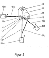
- Fig. 3 is a schematic diagram of a test setup with a force introduction element 11, which serves for example as a wheel replacement of an axle or vehicle test stand and which is connected in a suitable manner to the axle 12 to be tested.
- the force introduction element 11 has a joint arrangement or a joint node 13, which is arranged at the theoretical force introduction point or wheel contact point (RAP) 14.
- the joint node 13 consists of three play-free ball joints 15, 16, 17, which are connected to force transmission elements, for example tension / compression rods 15a, 16a, 17a.
- force or paths can be introduced into the joint node 13 via the force transmission elements and via actuating elements 15b, 16b, 17b.
- the actuating elements 15b, 16b, 17b can be designed, for example, as hydraulic actuating cylinders.
- the theoretical force introduction point or wheel contact point 14 coincides with the center of the ball joint 15, i.e. the ball joint 15 is arranged at the theoretical force introduction point 14.
- the two remaining joints 16 and 17 are in close proximity to joint 15 and RAP 14, respectively.
- the directions of action of the rods 15a, 16a, 17a are essentially perpendicular to one another and intersect at the wheel contact point 14 or at the theoretical point of force application.
- the effectiveness of the rod 15a defines the x direction, that of the rod 16a the y direction and that of the rod 17a the z direction.
- the bars 15a, 16a therefore form the xy plane, the bars 15a, 17a the xz plane and the bars 16a, 17a the yz plane.
- a further joint 18 is arranged on the force introduction element 11.
- This joint is connected to the rod 17a via an auxiliary rod 17c and serves to support the torque of the force introduction element 11 rotatably mounted on the axis 12, e.g. when longitudinal forces are introduced via the joint 15 and the rod 15a. If the force introduction element 11 is firmly connected to the axis 12, e.g. in tests with the wheel braked, the auxiliary rod 17c is omitted or it is switched off or removed.
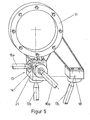
- FIG. 5 shows the joint arrangement 13 with the force introduction element 11 and the application of the auxiliary rod 17c in a perspective sketch.
- the reference numerals correspond to those in FIG. 3.
- the sketch also shows the base body 21 of the joint arrangement shown in FIGS. 4a-c in a more concrete, but still schematically illustrated form.
- the force introduction element 11 is in FIG. 5 as one in essence Lichen round element shown. However, as indicated in FIG. 3, it can also have a trapezoidal shape or another suitable shape.
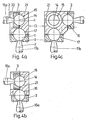
- the sections shown in FIGS. 4a-c through the joint arrangement or the joint node 13 with a base body 21 each pass through the theoretical force introduction point or wheel contact point 14.
- the base body 21 can be designed, for example, as a cubic or rectangular body and cylindrical approaches for individual ball joints exhibit.
- Fig. 4a with the section in the xz plane shows the play-free ball joint 15 with the ball head 1 and the ball pin 2.
- the ball pin 2 is connected to the rod 15a in a suitable manner, e.g. welded.
- the ball joint 15 is arranged in a recess 22 of the base body 21.
- a bearing shell 3 is provided with an opening, via which the ball head 1 is connected to the base body 21 in the manner described above.
- the clamping and loosening screws required for this are arranged on the bearing shell 3 and are only indicated schematically for the sake of clarity.
- the ball joint 17 is arranged in the base body 22 below the ball joint 15.
- the ball joint 17 is made larger than the ball joint 15, so that higher forces can be transmitted via the joint 17.
- a ball head 1 is connected to a ball pin 2 in ball joint 17 and this is connected to rod 17a. Via a bearing shell 3 provided with an opening, the ball head 1 is supported in the base body 21 without play by means of clamping and loosening screws.
- FIGS. 4b and 4c show the sections corresponding to FIG. 4a in the xy plane passing through the force introduction point 14 and the yz plane with the wheel contact point 14, the ball joints 15, 16, 17, the tension / compression rods 15a, 16a, 17a , the bearing shells 3 and the base body 21. All three ball joints can be seen in FIG. 4c, since they lie in the yz sectional plane shown here.
- the ball joints can also be arranged so that all joints are in the xy or xz plane.
- the joint node 13 can also have only two joints instead of three ball joints.
- the individual ball joints can be shown in a manner not shown by cuffs or similar sealing elements e.g. be sealed against dust.
- the sleeves or sealing elements can e.g. be arranged between the tension / compression rods 15a, 16a, 17a and the base body 21.
Landscapes
- Engineering & Computer Science (AREA)
- General Engineering & Computer Science (AREA)
- Mechanical Engineering (AREA)
- Physics & Mathematics (AREA)
- General Physics & Mathematics (AREA)
- Pivots And Pivotal Connections (AREA)
Applications Claiming Priority (4)
| Application Number | Priority Date | Filing Date | Title |
|---|---|---|---|
| DE3301543 | 1983-01-19 | ||
| DE19833301543 DE3301543A1 (de) | 1983-01-19 | 1983-01-19 | Spielfreies kugelgelenk, insbesondere fuer pruefeinrichtungen |
| DE3310064 | 1983-03-19 | ||
| DE19833310064 DE3310064A1 (de) | 1983-03-19 | 1983-03-19 | Gelenkanordnung mit spielfreien kugelgelenken, insbesondere fuer pruefeinrichtungen |
Publications (3)
| Publication Number | Publication Date |
|---|---|
| EP0114327A2 true EP0114327A2 (fr) | 1984-08-01 |
| EP0114327A3 EP0114327A3 (en) | 1985-01-16 |
| EP0114327B1 EP0114327B1 (fr) | 1987-03-18 |
Family
ID=25807619
Family Applications (1)
| Application Number | Title | Priority Date | Filing Date |
|---|---|---|---|
| EP83112734A Expired EP0114327B1 (fr) | 1983-01-19 | 1983-12-17 | Rotule sans jeu, en particulier pour dispositifs d'essai et ensemble rotule comportant de telles rotules |
Country Status (2)
| Country | Link |
|---|---|
| EP (1) | EP0114327B1 (fr) |
| DE (1) | DE3370363D1 (fr) |
Cited By (12)
| Publication number | Priority date | Publication date | Assignee | Title |
|---|---|---|---|---|
| EP0181411A1 (fr) * | 1984-11-03 | 1986-05-21 | Carl Schenck Ag | Dispositif d'application de forces dans un point (d'application de force) commun |
| EP0213504A3 (fr) * | 1985-08-15 | 1988-03-23 | Rockwell International Corporation | Chuck à mâchoires doubles et élément creux pour mâchoire de serrage |
| EP0183065A3 (en) * | 1984-11-29 | 1988-05-04 | Fritz Strater | Desk lamp |
| GB2296288A (en) * | 1994-12-16 | 1996-06-26 | Kenex | Mount for a radiation shield |
| US5720594A (en) * | 1995-12-13 | 1998-02-24 | Holmes Products Corp. | Fan oscillating in two axes |
| WO1998050707A1 (fr) | 1997-05-01 | 1998-11-12 | Mikron S.A. Agno | Joint articule hydrostatique |
| EP1209456A1 (fr) * | 2000-11-23 | 2002-05-29 | Benteler Automobiltechnik GmbH & Co. KG | Dispositif pour simuler l' influence des forces dans la roue d'un vehicule |
| WO2005106264A1 (fr) * | 2004-05-03 | 2005-11-10 | Wabtec Holding Corporation | Systeme auto-lubrifiant d'un systeme d'accouplement |
| FR3056654A1 (fr) * | 2016-09-29 | 2018-03-30 | Centre Technique Des Industries Mecaniques | Dispositif d'ancrage de l'extremite d'une tige pivotante |
| CN115165186A (zh) * | 2022-06-22 | 2022-10-11 | 华能国际电力股份有限公司大连电厂 | 一种汽轮机轴承内轴瓦紧力检测机构及检测方法 |
| EP4556878A1 (fr) * | 2023-11-14 | 2025-05-21 | Illinois Tool Works Inc. | Dispositif pour l'introduction de force dans un objet à tester |
| CN120445633A (zh) * | 2025-07-11 | 2025-08-08 | 上海天佑铁道新技术研究所股份有限公司 | 一种球铰密封圈检测装置 |
Family Cites Families (4)
| Publication number | Priority date | Publication date | Assignee | Title |
|---|---|---|---|---|
| NL303055A (fr) * | 1963-06-10 | |||
| US3744859A (en) * | 1969-05-15 | 1973-07-10 | Caterpillar Tractor Co | Multi-part bearing liner |
| GB2074337B (en) * | 1980-04-15 | 1983-11-16 | Univ Technology | Adjustable support for an optical or other instrument |
| FR2505952B1 (fr) * | 1981-05-15 | 1988-01-22 | Citroen Sa | Dispositif d'articulation a rotule multiple |
-
1983
- 1983-12-17 DE DE8383112734T patent/DE3370363D1/de not_active Expired
- 1983-12-17 EP EP83112734A patent/EP0114327B1/fr not_active Expired
Cited By (12)
| Publication number | Priority date | Publication date | Assignee | Title |
|---|---|---|---|---|
| EP0181411A1 (fr) * | 1984-11-03 | 1986-05-21 | Carl Schenck Ag | Dispositif d'application de forces dans un point (d'application de force) commun |
| EP0183065A3 (en) * | 1984-11-29 | 1988-05-04 | Fritz Strater | Desk lamp |
| EP0213504A3 (fr) * | 1985-08-15 | 1988-03-23 | Rockwell International Corporation | Chuck à mâchoires doubles et élément creux pour mâchoire de serrage |
| GB2296288A (en) * | 1994-12-16 | 1996-06-26 | Kenex | Mount for a radiation shield |
| US5720594A (en) * | 1995-12-13 | 1998-02-24 | Holmes Products Corp. | Fan oscillating in two axes |
| WO1998050707A1 (fr) | 1997-05-01 | 1998-11-12 | Mikron S.A. Agno | Joint articule hydrostatique |
| EP1209456A1 (fr) * | 2000-11-23 | 2002-05-29 | Benteler Automobiltechnik GmbH & Co. KG | Dispositif pour simuler l' influence des forces dans la roue d'un vehicule |
| WO2005106264A1 (fr) * | 2004-05-03 | 2005-11-10 | Wabtec Holding Corporation | Systeme auto-lubrifiant d'un systeme d'accouplement |
| FR3056654A1 (fr) * | 2016-09-29 | 2018-03-30 | Centre Technique Des Industries Mecaniques | Dispositif d'ancrage de l'extremite d'une tige pivotante |
| CN115165186A (zh) * | 2022-06-22 | 2022-10-11 | 华能国际电力股份有限公司大连电厂 | 一种汽轮机轴承内轴瓦紧力检测机构及检测方法 |
| EP4556878A1 (fr) * | 2023-11-14 | 2025-05-21 | Illinois Tool Works Inc. | Dispositif pour l'introduction de force dans un objet à tester |
| CN120445633A (zh) * | 2025-07-11 | 2025-08-08 | 上海天佑铁道新技术研究所股份有限公司 | 一种球铰密封圈检测装置 |
Also Published As
| Publication number | Publication date |
|---|---|
| EP0114327B1 (fr) | 1987-03-18 |
| EP0114327A3 (en) | 1985-01-16 |
| DE3370363D1 (en) | 1987-04-23 |
Similar Documents
| Publication | Publication Date | Title |
|---|---|---|
| EP0114327B1 (fr) | Rotule sans jeu, en particulier pour dispositifs d'essai et ensemble rotule comportant de telles rotules | |
| WO1999050121A1 (fr) | Dispositif permettant l'appui elastique d'un arbre de couplage d'un attelage a tampon central d'un vehicule ferroviaire | |
| DE3241373C2 (fr) | ||
| DE2934207A1 (de) | Homokinetisches wellengelenk | |
| DE2349680A1 (de) | Vorrichtung zur halterung eines ersten koerpers an einem zweiten koerper in einer solchen weise, dass eine relativbewegung zwischen den beiden koerpern nur in drei aufeinander senkrecht stehenden richtungen moeglich ist | |
| DE202018102171U1 (de) | Sensorhalter und Vorrichtung mit einem solchen Sensorhalter | |
| DE69303140T2 (de) | Lagesperrvorrichtung für eine verstellbare Lenksäule, zum Beispiel eines Kraftfahrzeuges und Lenksäuleeinrichtung mit so einer Vorrichtung | |
| DE3119491A1 (de) | Ueberlastschutz-kupplung | |
| DE3310064A1 (de) | Gelenkanordnung mit spielfreien kugelgelenken, insbesondere fuer pruefeinrichtungen | |
| DE2338579A1 (de) | Universalgelenk | |
| DE4415788A1 (de) | Schwenkflügelweiche | |
| DE69922444T2 (de) | Feder- Verriegelungsvorrichtung | |
| DE2742192A1 (de) | Elastische halterung mit blockiereinrichtung | |
| DE2738527A1 (de) | Vorrichtung zum spannen von kreiszylinderischen werkzeugteilen | |
| DE19735753A1 (de) | Drehstabanordnung | |
| DE69103085T2 (de) | Drehmomentbegrenzungseinrichtung und entfaltbares Verlängerungsstück eines, mit einer solchen Einrichtung ausgerüsteten, Raumflugkörpers. | |
| EP0479061A1 (fr) | Ressort à torsion | |
| EP0181411B1 (fr) | Dispositif d'application de forces dans un point (d'application de force) commun | |
| DD290849A5 (de) | Anordnung der achslager in einem laufwerk fuer schienenfahrzeuge | |
| DE923046C (de) | Gummihuelsenfeder fuer Gelenkverbindungen mit beschraenkter Raumbeweglichkeit | |
| DE9301268U1 (de) | Gelenkige Aufhängung | |
| DE2109044B2 (de) | Vorrichtung zum Verteilen von Richtkräften | |
| DE3235367C2 (fr) | ||
| EP4431405A1 (fr) | Dispositif de verrouillage pour verrouiller et libérer un premier composant par rapport à un second composant | |
| DE10107976B4 (de) | Lagerkombination |
Legal Events
| Date | Code | Title | Description |
|---|---|---|---|
| PUAI | Public reference made under article 153(3) epc to a published international application that has entered the european phase |
Free format text: ORIGINAL CODE: 0009012 |
|
| AK | Designated contracting states |
Designated state(s): CH DE FR GB LI |
|
| PUAL | Search report despatched |
Free format text: ORIGINAL CODE: 0009013 |
|
| AK | Designated contracting states |
Designated state(s): CH DE FR GB LI |
|
| 17P | Request for examination filed |
Effective date: 19850615 |
|
| 17Q | First examination report despatched |
Effective date: 19860312 |
|
| GRAA | (expected) grant |
Free format text: ORIGINAL CODE: 0009210 |
|
| AK | Designated contracting states |
Kind code of ref document: B1 Designated state(s): CH DE FR GB LI |
|
| REF | Corresponds to: |
Ref document number: 3370363 Country of ref document: DE Date of ref document: 19870423 |
|
| ET | Fr: translation filed | ||
| PLBE | No opposition filed within time limit |
Free format text: ORIGINAL CODE: 0009261 |
|
| STAA | Information on the status of an ep patent application or granted ep patent |
Free format text: STATUS: NO OPPOSITION FILED WITHIN TIME LIMIT |
|
| 26N | No opposition filed | ||
| PGFP | Annual fee paid to national office [announced via postgrant information from national office to epo] |
Ref country code: FR Payment date: 19911107 Year of fee payment: 9 |
|
| PGFP | Annual fee paid to national office [announced via postgrant information from national office to epo] |
Ref country code: CH Payment date: 19911121 Year of fee payment: 9 |
|
| PG25 | Lapsed in a contracting state [announced via postgrant information from national office to epo] |
Ref country code: LI Effective date: 19921231 Ref country code: CH Effective date: 19921231 |
|
| PG25 | Lapsed in a contracting state [announced via postgrant information from national office to epo] |
Ref country code: FR Effective date: 19930831 |
|
| REG | Reference to a national code |
Ref country code: CH Ref legal event code: PL |
|
| REG | Reference to a national code |
Ref country code: FR Ref legal event code: ST |
|
| PGFP | Annual fee paid to national office [announced via postgrant information from national office to epo] |
Ref country code: GB Payment date: 19961121 Year of fee payment: 14 |
|
| PGFP | Annual fee paid to national office [announced via postgrant information from national office to epo] |
Ref country code: DE Payment date: 19970221 Year of fee payment: 14 |
|
| PG25 | Lapsed in a contracting state [announced via postgrant information from national office to epo] |
Ref country code: GB Free format text: LAPSE BECAUSE OF NON-PAYMENT OF DUE FEES Effective date: 19971217 |
|
| GBPC | Gb: european patent ceased through non-payment of renewal fee |
Effective date: 19971217 |
|
| PG25 | Lapsed in a contracting state [announced via postgrant information from national office to epo] |
Ref country code: DE Free format text: LAPSE BECAUSE OF NON-PAYMENT OF DUE FEES Effective date: 19980901 |