EP4431405A1 - Dispositif de verrouillage pour verrouiller et libérer un premier composant par rapport à un second composant - Google Patents
Dispositif de verrouillage pour verrouiller et libérer un premier composant par rapport à un second composant Download PDFInfo
- Publication number
- EP4431405A1 EP4431405A1 EP23161460.3A EP23161460A EP4431405A1 EP 4431405 A1 EP4431405 A1 EP 4431405A1 EP 23161460 A EP23161460 A EP 23161460A EP 4431405 A1 EP4431405 A1 EP 4431405A1
- Authority
- EP
- European Patent Office
- Prior art keywords
- component
- locking device
- holding plate
- locked state
- holding
- Prior art date
- Legal status (The legal status is an assumption and is not a legal conclusion. Google has not performed a legal analysis and makes no representation as to the accuracy of the status listed.)
- Granted
Links
Images
Classifications
-
- B—PERFORMING OPERATIONS; TRANSPORTING
- B64—AIRCRAFT; AVIATION; COSMONAUTICS
- B64G—COSMONAUTICS; VEHICLES OR EQUIPMENT THEREFOR
- B64G1/00—Cosmonautic vehicles
- B64G1/22—Parts of, or equipment specially adapted for fitting in or to, cosmonautic vehicles
- B64G1/64—Systems for coupling or separating cosmonautic vehicles or parts thereof, e.g. docking arrangements
- B64G1/645—Separators
- B64G1/6457—Springs; Shape memory actuators
-
- B—PERFORMING OPERATIONS; TRANSPORTING
- B64—AIRCRAFT; AVIATION; COSMONAUTICS
- B64G—COSMONAUTICS; VEHICLES OR EQUIPMENT THEREFOR
- B64G1/00—Cosmonautic vehicles
- B64G1/22—Parts of, or equipment specially adapted for fitting in or to, cosmonautic vehicles
- B64G1/64—Systems for coupling or separating cosmonautic vehicles or parts thereof, e.g. docking arrangements
- B64G1/641—Interstage or payload connectors
- B64G1/642—Clamps, e.g. Marman clamps
Definitions
- the present description generally relates to a mechanism for locking and releasing a mechanical connection between two components.
- the description relates to a locking device for locking and releasing a first component relative to a second component.
- a locking device can be used as a launch lock in a satellite or other spacecraft, without, however, limiting the locking device to this intended use.
- two components must be mechanically fixed relative to each other and released when a certain condition occurs.
- the two components are fixed relative to each other in a first state (which can also be referred to as the locked state) and cannot move as long as one of these two components is subjected to a force that does not exceed a threshold value.
- a second state (which can also be referred to as the released state)
- the components can be moved relative to each other.
- a locking device can be used, which can basically assume both states and can be transferred from one state to the other.
- the aim is that the two components are fixed against each other in the locked state with the highest possible holding force. After the locking device has been moved into the released state, it should be possible to move the two components relative to each other with as many degrees of freedom as possible.
- Such locking devices may be used, for example and without limitation, in the context of satellites as launch safeguards to securely hold components in the satellite during the launch phase when high forces act on the satellite and strong vibrations occur, in order to prevent damage to those components or to the satellite caused by moving components.
- a locking device for such a purpose is described, for example, in the document WO 03/059741 A1 .
- a locking device for locking and releasing a first component relative to a second component.
- the locking device has a first component, a second component, a first retaining plate and a second retaining plate.
- the first component can be coupled to the first component.
- the second component can be coupled to the second Component can be coupled.
- the first component and the second component are arranged between the first holding plate and the second holding plate.
- the first component is spaced apart from the second component by a gap.
- the locking device can assume a locked state and a released state and is designed to be transferred from the locked state to the released state. In the locked state, the first component is immovably fixed with respect to the second component.
- the first component In the released state, the first component is freely movable with respect to the second component within a predetermined range.
- the first holding plate In the locked state, the first holding plate lies directly against both the first component and the second component, at least in sections, and in the locked state, the second holding plate lies directly against both the first component and the second component, at least in sections, so that a force acting on the first holding plate and the second holding plate is distributed over at least two load paths running alongside one another.
- the locking device can assume a locked state and a released or unlatched state.
- the locked state the first component is fixed in relation to the second component and cannot be moved if a force acting on the first component and/or second component is below a threshold value.
- the released state a relative movement between the first component and the second component is possible.
- relative movement is understood to mean that either the first component, or the second component, or the first and second components are moved.
- the locking device described here is designed for one-time use.
- the locking device holds two components rigidly to each other for a certain period of time and is set to the released state when a predetermined condition occurs. As soon as the locking device is in the released state, it for a longer period of time. It is not mandatory that the locking device be put into the locked state again, although this is not excluded.
- the first component and the second component are arranged between the first holding plate and the second holding plate.
- the two holding plates In the locked state, the two holding plates thus exert a force on the first and second components.
- the two holding plates move away from each other and at least one holding plate, preferably both holding plates, are spaced apart from the first component and the second component.
- the first holding plate is arranged opposite the second holding plate. In other words, the first component and the second component are sandwiched between the two holding plates.
- the first component is spaced apart from the second component by a gap both in the locked state and in the released state.
- the first component does not lie directly against the second component, but the force required to achieve fixation in the locked state is applied by the first retaining plate and the second retaining plate.
- the fact that the first component is freely movable in relation to the second component in the released state means that the first component can be moved translationally along three spatial axes and rotationally about three spatial axes in relation to the second component, within the predetermined range.
- the locking device thus enables the first component to be fixed relative to the second component and, after this fixation has been released, to be moved without restriction with six degrees of freedom (within a certain predetermined range).
- the locking device can be used, for example, as a lock for a payload in a spacecraft and is mainly used during a launch phase to fix the payload in the spacecraft while the external forces take effect during launch. Locking devices for this purpose are typically referred to as launch locks.
- the locking device can also be used in other fields to generally releasably attach a first component to a second component and to allow almost free movement of the first component relative to the second component after releasing the attachment between the first component and the second component.
- the first component of the locking device can be mechanically coupled to the first component, for example to a vehicle to which the second component is to be connected.
- the second component can in turn be mechanically connected to the second component. If the first component and the second component are locked relative to one another, then the first component and the second component are consequently also fixed relative to one another.
- the second component is rigidly fixed in a spacecraft during a launch phase.
- the force acting on the first component and/or second component can be vibrations and/or accelerations during the launch phase of a spacecraft.
- each of the two retaining plates rests directly on each of the two components.
- the first retaining plate rests directly on both the first component and the second component, at least in sections, i.e. a part of a surface of the first retaining plate rests on a part a surface of the first component and a part of a surface of the second component.
- the second holding plate lies directly at least in sections on both the first component and the second component, ie a part of a surface of the second holding plate lies on a part of a surface of the first component and a part of a surface of the second component.
- the holding force is distributed over at least two load paths running alongside one another.
- One load path runs from the first holding plate through the first component to the second holding plate and another load path runs from the first holding plate through the second component to the second holding plate.
- the holding force is thus distributed advantageously over the two components and ensures reliable fixation of the two components in the locked state.
- the locking device further comprises a holding arrangement, wherein the holding arrangement comprises a bolt which extends through the first holding plate and through the second holding plate, and wherein at least the first holding plate and also the first component are mounted on the bolt and designed to move along the bolt when the locking device is moved from the locked state to the released state.
- the holding arrangement comprises a bolt which extends through the first holding plate and through the second holding plate, and wherein at least the first holding plate and also the first component are mounted on the bolt and designed to move along the bolt when the locking device is moved from the locked state to the released state.
- the holding arrangement is designed to hold the components of the locking device and, in the locked state, to exert a force on the holding plates, which in turn then exert a force on the first component and the second component in order to fix them against each other.
- the bolt has, in particular, a straight extension.
- the bolt has a circular cross-section.
- Recesses through which the bolt extends are arranged in the first holding plate and in the second holding plate. In particular, these recesses have a cross-sectional area that is larger than the cross-sectional area of the bolt.
- Holding plates and components that are designed to move along the bolt should also have a sufficient guide length to be able to move along the bolt without jamming when the locking device is moved from the locked state to the released state.
- the locking device can also have additional guide pins along which the first holding plate and/or the second holding plate is guided when the locking device is moved from the locked state to the released state.
- the holding arrangement further comprises an engagement and a prestressing element, wherein the engagement is releasably fastened to the bolt in a certain position and in this position exerts a holding force on the first holding plate, whereby a holding force is exerted on the first holding plate in the direction of the first component and the second component, and wherein the prestressing element is movable along the bolt in order to exert a holding force on the second holding plate in the direction of the first component and the second component.
- the engagement and the biasing element each press a retaining plate towards the first component and the second component in order to fix the two components relative to each other.
- the engagement is, for example, brought into positive engagement with the bolt and is held in this position by a safety device.
- the pre-tensioning element is, for example, designed as a pre-tensioning nut so that a desired tightening torque can be applied to the second retaining plate.
- the pre-tensioning nut is, for example, tightened along a thread on the outer surface of the bolt.
- the engagement exerts a holding force on the first retaining plate in Direction of the preload nut and the preload nut in turn exerts a holding force on the second retaining plate in the direction of the engagement.
- the engagement is usually attached to a specific position on the bolt and holds this position, although engagements without a through bolt are also common and can be used.
- the preload element can take up various positions on the bolt and in particular can be moved along the longitudinal axis of the bolt in order to achieve a desired tightening torque and to exert a resulting holding force on the retaining plates and the first and second components.
- the engagement is initially immovably attached to the bolt and is held releasably in this position.
- a so-called fuse can be used, which presses the engagement against the outer surface of the bolt and thus holds the engagement in the corresponding position.
- the fuse can be released, for example, by applying an electric current to it, which melts part of the material of the fuse, thereby damaging the structural integrity of the fuse and releasing the connection between the engagement and the bolt. Now both the first holding plate and the engagement can move along the bolt and the locking device is in the released state.
- the engagement and the pre-tensioning element are located at fixed positions of the bolt and in these positions each exert a holding force on the adjacent retaining plate in order to thereby fix the first component in relation to the second component.
- the engagement is released from the bolt or the connection between the engagement and the bolt is released. This allows the engagement to move in the longitudinal direction of the bolt away from the pre-tensioning element.
- the two retaining plates can move away from the first component and the second component to release the first component with respect to the second component.
- the locking device further comprises a first spring and a second spring, wherein the first spring is arranged between, on the one hand, the first holding plate and, on the other hand, the first component and/or the second holding plate and is designed to press the first holding plate away from the first component and the second component when the locking device is moved from the locked state to the released state, and wherein the second spring is arranged between, on the one hand, the second holding plate and, on the other hand, the first component and/or the first holding plate and is designed to press the second holding plate away from the first component and the second component when the locking device is moved from the locked state to the released state.
- the term "spring” is used to represent an elastic element which is designed to perform the described function and to press a retaining plate away from the first component and/or the second component.
- the locking device only has a spring to press only one of the two holding plates away from the first component and the second component.
- the first spring and the second spring are designed as so-called compression springs.
- the springs are compressed between the respective retaining plate and the first and second components.
- the two springs press the retaining plates away from the first component and the second component. neither the first component nor the second component is attached to one of the holding plates. A relative movement between the first component and the second component is now possible in a certain area along and around all three spatial axes.
- the second and/or first retaining plate has a bulge which points in a direction away from the first component and the second component.
- the second and/or first retaining plate is designed to be convex with respect to the first component and the second component.
- the bulge is located in an area of the bolt in which the preloading element or the engagement exerts the holding force on the bulge in the locked state.
- the preloading element which is designed as a preload nut, is screwed along the bolt and moves the second retaining plate and/or the first retaining plate in the direction of the first component and the second component.
- the second and/or first retaining plate comes into contact with one of the components. If the preload nut is now tightened further, this leads to an elastic deformation of the bulge and the retaining plate is also pressed onto the component in the area of the bulge with which there was no contact.
- the bulge and the resulting internal tension of the retaining plate in the locked state optimize the distribution of the holding force exerted by the preload nut and/or the engagement on the retaining plate on the first component and the second component. Likewise, manufacturing tolerances in the first component and the second component and/or the two holding plates are compensated and yet a good distribution of the holding force on the first component and the second component is achieved.
- the second and/or first retaining plate is elastically deformable at least in the region of the bulge, so that a prestress is induced in the first retaining plate or second retaining plate when the locking device is in the locked state.
- the prestressing element exerts a force on the bulge and presses the second retaining plate against the first component and the second component.
- the second retaining plate is elastically deformable in the region of the bulge, the second retaining plate deforms depending on the force exerted by the prestressing element and adapts to the surface contour of the first component and the second component.
- the first component and the second component are preferably designed to be flat on the surface facing the second retaining plate. This means that the second retaining plate assumes its bulged or curved shape in the released state, whereas in the locked state it is substantially flat because the prestressing element presses the bulge against the first component and/or the second component.
- the first holding plate or the second holding plate has a positive locking element which, in the locked state of the locking device, is at least partially positioned in the gap between the first component and the second component.
- the form-locking element is preferably arranged only on one of the holding plates, i.e. either on the first holding plate or on the second holding plate, and in the locked state exerts a force on both the first component and the second component in order to fix the first component relative to the second component.
- the form-locking element has a conical shape and tapers in a direction towards the second holding plate (if the form-locking element is arranged on the first holding plate) or towards the first holding plate (if the form-locking element is arranged on the second holding plate).
- the retaining plates therefore not only prevent movement of the first component and the second component along the bolt, but also movement transverse to the longitudinal direction of the bolt and rotational movement around the longitudinal direction of the bolt.
- the form-locking element extends along the entire length of the gap in the locked state.
- the length of the gap is to be understood here as the extent of the gap in the circumferential direction around the bolt.
- the first retaining plate or the second retaining plate moves so far away from the first component and the second component that the positive locking element is moved completely out of the gap.
- the first component has a first contact surface which rests against the form-locking element in the locked state
- the second component has a second contact surface which rests against the form-locking element in the locked state
- both the first contact surface and the second contact surface run obliquely and are adapted to an external shape of the form-locking element
- the first component and/or the second component by an asymmetry along the gap and in a contact area with the form-locking element about a longitudinal axis of the bolt.
- first component and/or the second component are asymmetrical, a rotational movement of the first component and/or the second component about the longitudinal axis of the bolt is counteracted.
- the asymmetry is in particular a rotational asymmetry in the sense that the first component and/or the second component cannot be mapped onto itself at any angle of rotation during a rotational movement about the longitudinal axis of the bolt.
- the first component in the released state, is translationally movable with respect to the second component along three mutually orthogonal spatial axes and rotationally movable about these spatial axes.
- the locking device Due to the special structure of the locking device, a holding force is exerted in the locked state such that the first component and the second component are firmly fixed in all degrees of freedom relative to one another, i.e. movement along each of the three spatial axes as well as around these three spatial axes is reliably prevented. Conversely, after the locking device has been moved from the locked state to the released state, the first component is released with respect to the second component in order to be able to carry out a movement with the six degrees of freedom mentioned in a certain area.
- an opening is provided in the second component, in which the first component is arranged.
- the first component is smaller in terms of its size than the opening in the second component.
- the first component can therefore be placed in the opening in such a way that the first component is spaced circumferentially from the second component. In other words, this creates the gap that extends between the first component and the second component.
- the first component can move freely with respect to the second component after the first retaining plate and the second retaining plate move away from the first component and the second component in the released state.
- the free movement between the first component and the second component is typically limited to a certain range of motion or radius of motion.
- this does not represent a restriction for the components fixed with the locking device, because a component arranged in a satellite that must be fixed during launch and released afterwards often only needs to be moved within a certain range.
- a satellite is specified.
- the satellite has a housing with at least one wall and a locking device as described herein, wherein the locking device is fixed to the wall on the one hand and is mechanically coupled to a secured component within the housing on the other hand.
- the locking device is described here in the context of a specific application and can be used as a so-called launch lock to To secure a secured component in the satellite housing against unwanted movements and vibrations during a launch phase of the satellite in the locked state of the locking device so that the secured component itself does not suffer damage and does not cause damage to the satellite housing.
- the locking device is set to the released state and the previously secured component can now be moved freely in a certain area in relation to the satellite housing.
- the secured component within the satellite's housing can be a nominally actuated structure that is to be moved by motor within certain limits at the mission's destination.
- the locking device is used to protect both the bearing of this actuated structure and its drive from high loads. After the locking device has been moved from the locked state to the released state, the structure is no longer fixed in relation to the satellite and can be moved freely according to specifications and within certain limits.
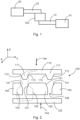
- Fig.1 shows a schematic representation of a locking device 100, which is designed to fix a first component 10 relative to a second component 20 and to release it when a certain condition occurs.
- the first component 10 is connected to the locking device 100 with a connecting element 12 and the second component 20 is connected to the locking device 100 with a connecting element 22.
- the connecting elements 12, 22 are, for example, rods or other rigid elements which establish a mechanical connection between the components 10, 20 and the locking device 100, and to fix or release the first component relative to the second component.
- the connecting element 12 can be connected to the first component 130 or the second component 140, whereas the connecting element 22 is connected to the other of these two components 130, 140.
- the components 130, 140 are immovable relative to each other and when the locking device 100 is in the released state, the components 130, 140 are movable relative to each other.
- the first component 10 is either fixed or movable relative to the second component 20 depending on the state of the locking device 100.
- the locking device 100 essentially consists of four components: the first holding plate 110, the second holding plate 120, the first component 130 and the second component 140.
- the first component 130 and the second component 140 are arranged like an intermediate layer between the first holding plate 110 and the second holding plate 120.
- the first component 130 can be moved relative to the second component 140 in a three-dimensional coordinate system with the mutually orthogonal spatial axes x, y, z in a certain area or within predetermined limits, translationally along each of these spatial axes and rotationally around each of these spatial axes.
- This freedom of movement is made possible by the fact that in the released state, which in Fig. 2 As shown, both holding plates 110, 120 are spaced apart from the first component 130 and the second component 140 and a gap 156 extends between the first component 130 and the second component 140.
- the first component 130 is located in a recess of the second component 140.
- the second component completely surrounds the first component, which in Fig.2 but is not apparent due to the sectional view.
- the first component 130 and the second component 140 have the same or almost the same extension (height) in the direction of the z-axis.
- Both the first component 130 and the second component 140 each have an inclined contact surface 131, 141 towards the gap 156.
- the contact surfaces 131, 141 together with the gap 156 form a funnel-shaped cross-section.
- the form-fitting element 111 of the first holding plate 110 is introduced into this funnel-shaped opening when a force 154 moves the first holding plate 110 in the direction of the first component 130 and the second component 140.
- the first surface 112 of the form-locking element 111 comes to rest on the contact surface 141 and the second surface 113 of the form-locking element 111 comes to rest on the contact surface 131.
- the form-locking element 111 when inserted into the gap 156, helps to prevent a relative movement of the first and second components 130, 140 in the xy plane (as the Fig.3 can be removed, the form-locking element 111 runs in the xy plane around the first component 130).
- the contact surface 131 is a circumferential surface on the first component 130 and the contact surface 141 is a circumferential surface on the second component 140.
- the second holding plate 120 is shown in the illustration of the Fig. 2 from below against the first component 130 and the second component 140, via a force 154.
- a holding force acting on the two holding plates 110, 120 in the direction of the first component 130 and the second component 140 is distributed over two load paths 150, 152.
- the first load path 150 runs from the second holding plate 120 over the first component 130, the contact surface 131, and the second surface 113 into the first holding plate 110.
- the second load path 152 runs from the second holding plate 120 over the second component 140, the contact surface 141, and the first surface 112 into the first holding plate 110.
- These two load paths 150, 152 which in Fig. 2 shown in connection with the contact surfaces 131, 141 and the surfaces 112, 113 of the form-locking element 111, are formed circumferentially along the contact surfaces 131, 141.
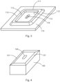
- Fig.3 shows an isolated representation of the first holding plate 110 from a perspective of the underside of the first holding plate 110, i.e. the side which faces the first component 130 and the second component 140.
- the first holding plate 110 contains a plate-like base body, on one surface of which the form-locking element 111 is arranged as a circumferential elevation (in this case as a truncated pyramid) with a substantially rectangular shape with rounded corners.
- the holding plate 110 and the form-locking element 111 can be designed as a single piece.
- An opening 118 extends through the first holding plate 110, surrounded by the form-locking element 111.
- a bolt extends through this opening 118, which holds and guides the first holding plate when the locking element is in the locked state or is placed in the released state.
- the opening 118 can be designed as a normal cylindrical bore. However, it can also have a different cross-section and can, for example, be an elongated hole.
- Fig.4 shows a schematic representation of the first component 130 with the bevelled contact surface 131 on which the form-locking element 111 of the first holding plate 110 rests, wherein the contact surface 131 is formed circumferentially around the first component 130.
- a component 10, 20 (see Fig.1 ) as described below with reference to Figs. 7 and 8 will be described later.
- An opening 135 extends through the first component 130.
- Fig.5 shows a schematic representation of the second component 140 with a central opening 143.
- the first component 130 is arranged in the central opening 143 in the assembled state and is spaced apart from the second component, so that the first component can be moved freely in the central opening 143 within certain limits, i.e. along three spatial axes and around these three spatial axes.
- One edge of the second component 140 is bevelled towards the central opening 143 and forms the circumferential contact surface 141.
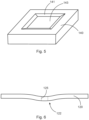
- Fig.6 shows a schematic representation of the second holding plate 120.
- the second holding plate 120 contains a bulge 122 and an opening 125, which is shown here in dashed lines.
- a bolt (similar to the opening 118 of the first holding plate 110) extends through the opening 125 in order to move the first holding plate 110 and the second holding plate 120 towards each other and to exert a corresponding holding force.
- the holding force of the bolt initially acts on the bulge 122, so that the areas to the left and right of the bulge initially act on the second component when the second holding plate 120 is moved into the locked state.
- the second holding plate 120 deforms in the area of the bulge and the bulge is pressed onto the first component 130. In this state, the second holding plate 120 is pre-tensioned.
- a holding force also acts reliably on both components 130, 140 if the height of the components 130, 140 differs due to component, manufacturing and assembly tolerances.
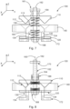
- Fig.7 shows a locking device 100 in an unlocked or released state.
- the first component 130 can be Relative to the second component 140, it can move within certain limits, namely along each of the three axes x, y, z, as well as around each of these axes.
- the components of the locking device 100 are arranged around a retaining arrangement 161 with a bolt 162.
- the retaining arrangement 161 includes an elongated bolt 162 with a longitudinal axis 163.
- An engagement 164 is lockable to the bolt in a predetermined position and is held in this position by a safety catch (when the locking device is in the locked state) and can be released from this position (to place the locking device in the released state).
- the engagement is adjacent to the first retaining plate 110.
- a biasing element 168 is arranged, for example in the form of a nut.
- the biasing element 168 is arranged adjacent to the second retaining plate 120.
- the bolt 162 extends through the opening 118 of the first retaining plate 110 (see Fig.3 ) and through the opening 125 of the second holding plate 120 (see Fig.6 ).
- the first component 130 and the second component 140 are arranged between the holding plates 110, 120.
- the bolt 162 extends through the opening 135 of the first component 130 (see Fig.4 ).
- the opening 135 has a cross-section which is larger than the cross-section of the bolt 162, so that the first component 130 can move along the longitudinal direction of the bolt 162, although the bolt 162 extends through its opening 135.
- the locking device 100 has a first spring 158 between the first component 130 and the first holding plate 110 and a second spring 160 between the first component 130 and the second holding plate 120.
- the springs 158, 160 press the holding plates 110, 120 away from the components 130, 140 and ensure, for example, that the first component is arranged centrally between the two holding plates 110, 120 in an unloaded state so that the second Component 140 does not adjoin one of the holding plates 110, 120. This allows free movement of the second component 140 relative to the first component 130.
- the first component 130 has a hat-like profile with a plurality of legs 134 that extend away from the first component 130 and through the second holding plate 120. With these legs 134, the first component can be attached to a support 172, wherein the support 172 can be a mounting location on a vehicle wall.
- the support 172 forms the first component 10 as shown in Fig.1
- the second component 20 can be attached to the second part 140.
- the first holding plate 110 and the second holding plate 120 are moved against the resistance of the springs 158, 160 in the direction of the first and second components 130, 140, with a corresponding force 154 (see Fig. 2 ) and locked in this position by fixing the engagement 164 in this position and tensioning the pretensioning element 168 with a required strength.
- the locked state is in Fig.8 shown.
- the first component 130 and the second component 140 are fixed between the two holding plates 110, 120.
- the engagement 164 is fixed at a predetermined position on the bolt 162 and is held in this position by a fuse 166.
- the fuse 166 is, for example, a fuse which can be electrically released by applying a current to the fuse which causes the fuse to melt.
- the engagement 164 then releases from the bolt and is pressed together with the first holding plate 110 along the longitudinal axis 163 of the bolt in the direction of the limiter 170 at one end of the bolt.
- the limiter 170 ensures that the engagement 164 and the first holding plate 110 are not completely detached from the locking device 100.
- the retaining plate 110 is secured by means of a bolt on the first component 130 or on the
- the second retaining plate 120 is guided by guide pins (not shown) mounted on the second retaining plate 120, and the limiter 170 is attached to these guide pins. While the engagement 164 and the first retaining plate 110 are pressed towards the limiter by the first spring 158, the second spring 160 presses the second retaining plate 120 away from the first component 130.
- the second holding plate 120 is curved in the direction of the pre-tensioning element 168 or has the bulge at the point where the second holding plate 120 rests against the pre-tensioning element 168.
- the second holding plate 120 returns to its original shape with the bulge.
- the second holding plate 120 rests on the first component 130 and the second component 140.
- the biasing element 168 typically does not change its position on the bolt 162. Rather, the fixation of the engagement 164 on the bolt is simply released and the second retaining plate 120 moves away from the first retaining plate 110, the first component 130 and the second component 140. Conversely, when the locking device is locked, the engagement 164 is first brought into a desired position and the biasing element 168 (for example a clamping nut) is further tightened in order to apply a desired holding force to the first and second components.
- the biasing element 168 for example a clamping nut
- the locking device 100 uses a locking bolt 162 (with electronic triggering of the engagement 164 via the safety device 166) as well as fits for force transmission to the holding plates 110, 120.
- a Form-locking element 111 is used as a fit with opposite release directions and is designed to transfer mechanical loads sequentially. In this way, after release, the two components 130, 140 to be locked against each other no longer necessarily block each other in at least the opposite release direction (as with simple form-locks).
- the aim is to hold the locking device 100 in the locked state with a single holding arrangement 161, which is advantageous for reasons of reliability. Although only one holding arrangement is used, simultaneous force-locking of both fits via the form-locking element 111 should be ensured despite manufacturing tolerances.
- the idea here is to distribute the preload applied by the holding bolt 162 (usually a few 10 kN) evenly over both fits (surfaces 112 and 113) via a correspondingly stiff spring element. This is achieved by applying the preload of the retaining bolt to the bulge 122 of the second retaining plate 120, and the preload presses this bulge to the first component 130 and the second component 140 by elastic deformation of the second retaining plate.
- the load transfer between the support 172 and the second component 140 takes place via two fits, namely the surfaces 112, 113 of the form-locking element 111 and the first holding plate 110.
- the preload of a single bolt 162 is distributed to both fits in a desired ratio via the second holding plate 120, which is designed as a spring element. Both the first holding plate 110 and the second holding plate 120 are retracted in the open state, whereby all degrees of freedom for movement between the first component 130 and the second component 140 are released.
- the preload is applied via a preload nut 168 and the locking device 100 is set to the released state via a fuse 166.
- the bolt 162 remains in the system in the released state and - depending on the design of the engagement 164 - can simultaneously be used as a defined stop for the two holding plates 110, 120.
- the support 172 can also serve as a stop for the second holding plate 120, and/or the limiter 170 for the first holding plate 110 can be attached to separate guide pins.
- both fits 112, 113 are released in the same direction of movement, the preload force is introduced back into the bolt 162 via the second retaining plate 120.
- This second retaining plate 120 simultaneously takes over the function of evenly distributing the preload, ie in the locked state, the second retaining plate 120 (as in Fig.8 indicated) elastically deformed and thus pre-stressed.
- both retaining plates 110, 120 can be removed from the two locked components 130, 140 by spring force with one or more spring elements 158, 160 along the longitudinal axis 163 of the bolt 162. This is shown in Fig.7 outlined.
- the upper holding plate 110 can also be moved along additional guide pins (not shown).
- slightly different preload forces may be required in order to be able to absorb at least a specified maximum load (in all degrees of freedom).
- the condition here is that the total load in the preload direction must not exceed the preload so that no movement can occur in the respective fit.
- the rigidity of the lower holding plate 120 and the preload in the bolt 162 can be selected accordingly.
- the required preload forces in the bolt 162 are correspondingly higher (typically by a factor of ⁇ 2).
- the lower holding plate 120 is typically only elastically deformed in the locked configuration.
- a modified geometry of the retaining plate is also possible, e.g. it can be constructed from two discs placed on top of each other, which are connected inside and outside, but have a gap in the middle.
- the second holding plate 120 can be circular and have inner and outer force-transmitting contact surfaces to the first and second components 130, 140. Since the second holding plate 120 and the first component 130 overlap, corresponding recesses are provided in the second holding plate 120 and the first component 130. An odd number of recesses is preferable here in order to prevent mirror symmetries and thus maximize mechanical stability.
- the flexible area is located between the inner and outer contact surfaces. The material in the flexible area can be thinner than in the contact surfaces, depending on the required preload force.
- the contact surfaces can be designed as flat contacts or as line contacts or as point contacts, as long as the system together with the first holding plate is not mechanically overdetermined as a result.
- the inner contact can be designed as a cone and the outer contact as a flat contact or via a spherical contact between a surface and an annular elevation.
- the geometry or symmetry of the actual fits determines how many degrees of freedom the mechanism can securely lock. If simple conical fits are used, all three displacements along the x, y, z axes are geometrically blocked, but rotation about the bolt 162 is only possible via static friction. The other two rotations can also only transmit comparatively small torques - depending on the cone angle.
- the fits can transmit high torques in these degrees of freedom, and with additional structuring in the tangential direction, high torques about the bolt axis can also be transmitted.
- the locking device can therefore be used to fix three to six degrees of freedom.
- the lower spring 160 can apply a higher spring force than the upper spring 158 in order to move the holding plates to their well-defined stops.
- the lower retaining plate 120 is caught by a stop on the first component 130, and the upper retaining plate 110 by a stop 170 on the bolt 162 or on one or more guide pins. Compared to the preload of the bolt 162, the preload of the springs (acting in the opposite direction) is negligible.
- the second retaining plate 120 and the bolt 162 impulsively introduce forces (so-called shock loads) into the second component 140, since the pre-stressed second retaining plate 120 is supported here.
- the first retaining plate 110 is also pre-stressed - analogous to the second retaining plate 120 - the introduced forces can be balanced and minimized.
- the potential energy stored in the pre-stressed retaining plates 110, 120 is not significantly greater than the potential energy stored in the bolt 162, ie the deformations are small and the stiffnesses are large. This potential disadvantage is thus limited compared to the prior art.
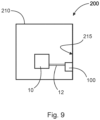
- Fig.9 shows a satellite 200 with a housing 210 and a wall 215.
- the locking device 100 is attached to the wall 215, for example by the first component 130 as in Figs. 7 and 8 shown is screwed to the wall.
- a first component 10, which must be rigidly fixed during the launch phase of the satellite, is connected to the second component via a connecting element 12.
- the first component 10 is, for example, a telescope which must be moved during a mission, but must be held rigidly during the launch phase in order not to damage the mechanism provided for the movement.
- the exemplary application shown for the locking device 100 is not to be understood as limiting. Rather, the locking device can also be used in other applications in which a component can be released with respect to another component upon the occurrence of a certain condition in order to enable relative movement between the two components.
Landscapes
- Engineering & Computer Science (AREA)
- Remote Sensing (AREA)
- Aviation & Aerospace Engineering (AREA)
- Mechanical Engineering (AREA)
- Clamps And Clips (AREA)
- Connection Of Plates (AREA)
Priority Applications (1)
| Application Number | Priority Date | Filing Date | Title |
|---|---|---|---|
| EP23161460.3A EP4431405B1 (fr) | 2023-03-13 | 2023-03-13 | Dispositif de verrouillage pour verrouiller et libérer un premier composant par rapport à un second composant |
Applications Claiming Priority (1)
| Application Number | Priority Date | Filing Date | Title |
|---|---|---|---|
| EP23161460.3A EP4431405B1 (fr) | 2023-03-13 | 2023-03-13 | Dispositif de verrouillage pour verrouiller et libérer un premier composant par rapport à un second composant |
Publications (2)
| Publication Number | Publication Date |
|---|---|
| EP4431405A1 true EP4431405A1 (fr) | 2024-09-18 |
| EP4431405B1 EP4431405B1 (fr) | 2025-12-24 |
Family
ID=85601698
Family Applications (1)
| Application Number | Title | Priority Date | Filing Date |
|---|---|---|---|
| EP23161460.3A Active EP4431405B1 (fr) | 2023-03-13 | 2023-03-13 | Dispositif de verrouillage pour verrouiller et libérer un premier composant par rapport à un second composant |
Country Status (1)
| Country | Link |
|---|---|
| EP (1) | EP4431405B1 (fr) |
Citations (4)
| Publication number | Priority date | Publication date | Assignee | Title |
|---|---|---|---|---|
| WO2003059741A1 (fr) | 2002-01-15 | 2003-07-24 | Honeywell International Inc. | Dispositif de verrouillage de lancement pour charges utiles de vaisseau spatial |
| US20170096240A1 (en) * | 2015-10-02 | 2017-04-06 | The Boeing Company | Dual Port Payload Attach Ring Compatible Satellite |
| CN107628278A (zh) * | 2017-07-31 | 2018-01-26 | 北京空间飞行器总体设计部 | 具有自主导向和连接功能的在轨可更换单元 |
| US20180223947A1 (en) * | 2015-08-07 | 2018-08-09 | Moog Inc. | Payload shock and vibration isolator |
-
2023
- 2023-03-13 EP EP23161460.3A patent/EP4431405B1/fr active Active
Patent Citations (4)
| Publication number | Priority date | Publication date | Assignee | Title |
|---|---|---|---|---|
| WO2003059741A1 (fr) | 2002-01-15 | 2003-07-24 | Honeywell International Inc. | Dispositif de verrouillage de lancement pour charges utiles de vaisseau spatial |
| US20180223947A1 (en) * | 2015-08-07 | 2018-08-09 | Moog Inc. | Payload shock and vibration isolator |
| US20170096240A1 (en) * | 2015-10-02 | 2017-04-06 | The Boeing Company | Dual Port Payload Attach Ring Compatible Satellite |
| CN107628278A (zh) * | 2017-07-31 | 2018-01-26 | 北京空间飞行器总体设计部 | 具有自主导向和连接功能的在轨可更换单元 |
Also Published As
| Publication number | Publication date |
|---|---|
| EP4431405B1 (fr) | 2025-12-24 |
Similar Documents
| Publication | Publication Date | Title |
|---|---|---|
| DE102009008188B4 (de) | Befestigungsvorrichtung für ein Modulelement in einem Flugzeug und Befestigungssystem | |
| EP2934360B1 (fr) | Bras de support médical | |
| DE102018209104B4 (de) | Verfahren zum Herstellen einer Batterieanordnung | |
| DE69702395T2 (de) | System zum sperren einer relativen bewegung zwischen zwei körpern, in zumindest einem sinn einer vorgegebenen richtung | |
| DE102021103203B3 (de) | Aktor mit einem Draht aus einer Formgedächtnislegierung und Vorrichtung zur Freigabe eines Bolzens mit einem solchen Aktor | |
| EP0275441B1 (fr) | Dispositif de serrage | |
| DE10009978C2 (de) | Vorrichtung zur Befestigung einer Fahrzeugantenne | |
| DE10043631C2 (de) | Linearbetätigungsvorrichtung, insbesondere für Raumfahrzeuge sowie Solargenerator-Entfaltsystem | |
| WO2019029865A1 (fr) | Dispositif d'application d'une crémaillère | |
| WO2014202076A1 (fr) | Système de réglage pourvu d'une unité de verrouillage | |
| EP0114327A2 (fr) | Rotule sans jeu, en particulier pour dispositifs d'essai et ensemble rotule comportant de telles rotules | |
| EP4431405B1 (fr) | Dispositif de verrouillage pour verrouiller et libérer un premier composant par rapport à un second composant | |
| DE102019118494A1 (de) | Montagesystem, Verfahren zum Montieren eines Bauteils, Bauteilanordnung und Luftfahrzeug | |
| EP4219304B1 (fr) | Dispositif d'accouplement pour une bielle de liaison | |
| DE102021119937B4 (de) | Dämpfungssystem und Linearaktuator | |
| EP3926180B1 (fr) | Dispositif de fixation doté d'un élément de fixation doté d'un actionneur électroactif en polymère | |
| DE69103085T2 (de) | Drehmomentbegrenzungseinrichtung und entfaltbares Verlängerungsstück eines, mit einer solchen Einrichtung ausgerüsteten, Raumflugkörpers. | |
| DE202022105768U1 (de) | Anschlagpunkt | |
| DE102024133516B3 (de) | Aktuatormodul mit Dämpfungssystem | |
| DE102024132621B3 (de) | Verriegelungseinrichtung | |
| DE102021006717B4 (de) | Dämpfungssystem und Linearaktuator | |
| DE102024133180B3 (de) | Vorrichtung zur Trennung zweier Raketenstufen | |
| AT525871B1 (de) | Tisch mit beweglichem Führungselement | |
| EP3588655B1 (fr) | Élément de compensation de tolérance pour un système de maintien d'un accumulateur d'énergie | |
| WO2020025828A1 (fr) | Broche à moteur destinée à une machine, en particulier à une machine-outil, dotée d'un agencement de paliers précontraint, et procédé de montage d'une broche à moteur de ce type |
Legal Events
| Date | Code | Title | Description |
|---|---|---|---|
| PUAI | Public reference made under article 153(3) epc to a published international application that has entered the european phase |
Free format text: ORIGINAL CODE: 0009012 |
|
| STAA | Information on the status of an ep patent application or granted ep patent |
Free format text: STATUS: THE APPLICATION HAS BEEN PUBLISHED |
|
| AK | Designated contracting states |
Kind code of ref document: A1 Designated state(s): AL AT BE BG CH CY CZ DE DK EE ES FI FR GB GR HR HU IE IS IT LI LT LU LV MC ME MK MT NL NO PL PT RO RS SE SI SK SM TR |
|
| STAA | Information on the status of an ep patent application or granted ep patent |
Free format text: STATUS: REQUEST FOR EXAMINATION WAS MADE |
|
| 17P | Request for examination filed |
Effective date: 20241008 |
|
| RBV | Designated contracting states (corrected) |
Designated state(s): AL AT BE BG CH CY CZ DE DK EE ES FI FR GB GR HR HU IE IS IT LI LT LU LV MC ME MK MT NL NO PL PT RO RS SE SI SK SM TR |
|
| GRAP | Despatch of communication of intention to grant a patent |
Free format text: ORIGINAL CODE: EPIDOSNIGR1 |
|
| STAA | Information on the status of an ep patent application or granted ep patent |
Free format text: STATUS: GRANT OF PATENT IS INTENDED |
|
| INTG | Intention to grant announced |
Effective date: 20250729 |
|
| GRAS | Grant fee paid |
Free format text: ORIGINAL CODE: EPIDOSNIGR3 |
|
| GRAA | (expected) grant |
Free format text: ORIGINAL CODE: 0009210 |
|
| STAA | Information on the status of an ep patent application or granted ep patent |
Free format text: STATUS: THE PATENT HAS BEEN GRANTED |
|
| AK | Designated contracting states |
Kind code of ref document: B1 Designated state(s): AL AT BE BG CH CY CZ DE DK EE ES FI FR GB GR HR HU IE IS IT LI LT LU LV MC ME MK MT NL NO PL PT RO RS SE SI SK SM TR |
|
| REG | Reference to a national code |
Ref country code: CH Ref legal event code: F10 Free format text: ST27 STATUS EVENT CODE: U-0-0-F10-F00 (AS PROVIDED BY THE NATIONAL OFFICE) Effective date: 20251224 Ref country code: GB Ref legal event code: FG4D Free format text: NOT ENGLISH |
|
| REG | Reference to a national code |
Ref country code: DE Ref legal event code: R096 Ref document number: 502023002547 Country of ref document: DE |
|
| REG | Reference to a national code |
Ref country code: LT Ref legal event code: MG9D |
|
| PG25 | Lapsed in a contracting state [announced via postgrant information from national office to epo] |
Ref country code: NO Free format text: LAPSE BECAUSE OF FAILURE TO SUBMIT A TRANSLATION OF THE DESCRIPTION OR TO PAY THE FEE WITHIN THE PRESCRIBED TIME-LIMIT Effective date: 20260324 |
|
| PGFP | Annual fee paid to national office [announced via postgrant information from national office to epo] |
Ref country code: DE Payment date: 20260319 Year of fee payment: 4 |
|
| PG25 | Lapsed in a contracting state [announced via postgrant information from national office to epo] |
Ref country code: FI Free format text: LAPSE BECAUSE OF FAILURE TO SUBMIT A TRANSLATION OF THE DESCRIPTION OR TO PAY THE FEE WITHIN THE PRESCRIBED TIME-LIMIT Effective date: 20251224 Ref country code: HR Free format text: LAPSE BECAUSE OF FAILURE TO SUBMIT A TRANSLATION OF THE DESCRIPTION OR TO PAY THE FEE WITHIN THE PRESCRIBED TIME-LIMIT Effective date: 20251224 |
|
| PGFP | Annual fee paid to national office [announced via postgrant information from national office to epo] |
Ref country code: AT Payment date: 20260301 Year of fee payment: 4 |
|
| PG25 | Lapsed in a contracting state [announced via postgrant information from national office to epo] |
Ref country code: RS Free format text: LAPSE BECAUSE OF FAILURE TO SUBMIT A TRANSLATION OF THE DESCRIPTION OR TO PAY THE FEE WITHIN THE PRESCRIBED TIME-LIMIT Effective date: 20260324 |
|
| PGFP | Annual fee paid to national office [announced via postgrant information from national office to epo] |
Ref country code: FR Payment date: 20260323 Year of fee payment: 4 |
|
| PG25 | Lapsed in a contracting state [announced via postgrant information from national office to epo] |
Ref country code: LV Free format text: LAPSE BECAUSE OF FAILURE TO SUBMIT A TRANSLATION OF THE DESCRIPTION OR TO PAY THE FEE WITHIN THE PRESCRIBED TIME-LIMIT Effective date: 20251224 |