EP0114349A2 - Appareil de diagnostic par résonance magnétique nucléaire - Google Patents
Appareil de diagnostic par résonance magnétique nucléaire Download PDFInfo
- Publication number
- EP0114349A2 EP0114349A2 EP83112855A EP83112855A EP0114349A2 EP 0114349 A2 EP0114349 A2 EP 0114349A2 EP 83112855 A EP83112855 A EP 83112855A EP 83112855 A EP83112855 A EP 83112855A EP 0114349 A2 EP0114349 A2 EP 0114349A2
- Authority
- EP
- European Patent Office
- Prior art keywords
- signal
- nmr signals
- signal components
- quadrature
- ratio
- Prior art date
- Legal status (The legal status is an assumption and is not a legal conclusion. Google has not performed a legal analysis and makes no representation as to the accuracy of the status listed.)
- Granted
Links
Images


Classifications
-
- A—HUMAN NECESSITIES
- A61—MEDICAL OR VETERINARY SCIENCE; HYGIENE
- A61B—DIAGNOSIS; SURGERY; IDENTIFICATION
- A61B5/00—Measuring for diagnostic purposes; Identification of persons
- A61B5/05—Detecting, measuring or recording for diagnosis by means of electric currents or magnetic fields; Measuring using microwaves or radio waves
- A61B5/055—Detecting, measuring or recording for diagnosis by means of electric currents or magnetic fields; Measuring using microwaves or radio waves involving electronic [EMR] or nuclear [NMR] magnetic resonance, e.g. magnetic resonance imaging
-
- G—PHYSICS
- G01—MEASURING; TESTING
- G01R—MEASURING ELECTRIC VARIABLES; MEASURING MAGNETIC VARIABLES
- G01R33/00—Arrangements or instruments for measuring magnetic variables
- G01R33/20—Arrangements or instruments for measuring magnetic variables involving magnetic resonance
- G01R33/44—Arrangements or instruments for measuring magnetic variables involving magnetic resonance using nuclear magnetic resonance [NMR]
- G01R33/48—NMR imaging systems
- G01R33/54—Signal processing systems, e.g. using pulse sequences ; Generation or control of pulse sequences; Operator console
- G01R33/56—Image enhancement or correction, e.g. subtraction or averaging techniques, e.g. improvement of signal-to-noise ratio and resolution
-
- G—PHYSICS
- G01—MEASURING; TESTING
- G01R—MEASURING ELECTRIC VARIABLES; MEASURING MAGNETIC VARIABLES
- G01R33/00—Arrangements or instruments for measuring magnetic variables
- G01R33/20—Arrangements or instruments for measuring magnetic variables involving magnetic resonance
- G01R33/28—Details of apparatus provided for in groups G01R33/44 - G01R33/64
- G01R33/32—Excitation or detection systems, e.g. using radio frequency signals
- G01R33/36—Electrical details, e.g. matching or coupling of the coil to the receiver
- G01R33/3621—NMR receivers or demodulators, e.g. preamplifiers, means for frequency modulation of the MR signal using a digital down converter, means for analog to digital conversion [ADC] or for filtering or processing of the MR signal such as bandpass filtering, resampling, decimation or interpolation
Definitions
- This invention relates to a nuclear magnetic resonance diagnostic apparatus which utilizes the nuclear magnetic resonance phenomenon (referred to as "NMR” phenomenon hereinafter) so as to noninvasively measure information concerning the spin density and relaxation time of a specific atomic nucleus or a proton within a selected sectional slice plane of an object to be examined, e.g., a patient, for which a tomographic image is obtained with a high S/N ratio.
- NMR nuclear magnetic resonance phenomenon
- Atomic nuclei are composed of protons and neutrons. It is generally considered that they are spinning as a whole like a top.
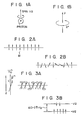
- an atomic nucleus of hydrogen (lH) is comprised of one proton which is spinning indicated by spin quantum number 1/2 as shown in Fig. lA.
- Fig. 1B since the proton holds a positive charge (e + ), an equivalent phenomenon can be conceived in Fig. 1B that in connection with rotations of the nuclei of hydrogen, a current corresponding to the above positive charge may flow in a small coil. As a result, a magnetic moment $ occurs.
- a respective nucleus of hydrogen can be regarded as a very small magnet.
- a difference between two energy levels is given by formula (1); where Y is a gyromagnetic ratio (the ratio between the magnet and mechanical moments), h is a Plank's constant and K is equal to h/2 ⁇ .
- ⁇ H o ⁇ H o (,i.e., Larmor angular velocity).
- an electromagnetic wave normally a radiofrequency wave
- AE energy level's difference
- the nuclei in one object which have a respective spin angular momentum
- it is possible to pick up a resonance of a specific atomic nuclues only because each of the nuclei has its specific gyromagnetic ratio y, and each of them has different resonance frequency.
- an amplitude of the resonant signal is measured, the density of the atomic nucleus in the object can be obtained.
- the nucleus which has been excited to the high energy level returns to the lower energy level after the occurence of the nuclear magnetic resonance and a period of time that is defined by a time constant, so-called “relaxation time".
- the relaxation time includes a spin-lattice relaxation time "Tl” and a spin-spin relaxation time "T2".
- the spin-lattice relaxation time "Tl” and the spin-spin relaxation time "T2" are such time constants that they are decided depending upon the combination of the composition. For example, values of those relaxation times for the normal tissue are different from that for the malignant tumor.
- NMR signals introduced in the present specification involve echo pulses, or echo pulse signals and also free induction decay signals (referred to as "FID signals” hereinafter).
- FID signals free induction decay signals
- NMR-CT apparatus Nuclear Magnetic Resonance-Computerized Tomographic Apparatus
- phase detection techinque is newly introduced in order to utilize a frequency information of the detected echo signals.
- the echo signals are very weak, and randam noises caused by the receiver channels and the object are superimposed to the above-described very weak echo signals, resulting in a low S/N ratio. Consequently there exists an extreme difficulty that only pure signals induced by the NMR phenomenon are selectively detected.
- a nuclear magnetic resonance diagnostic apparatus comprising:
- such an NMR diagnostic apparatus wherein an NMR signal induced by the NMR phenomenon is improved with respect to its signals to noise ratio.
- this detected signal is processed in an S/N ratio improving circuit.
- a first cosine signal component (referred to as “cos signal”) and also a first sine signal component (referred to as “sin signal”) of the detected NMR signals which were taken in a first examination period at the given slice of the object and temporarily stored in the memory means, are summed in phase by second ones which were taken in a second examination period at the same slice as in the first examination period and temporarily stored in the memory means.
- signals shown in Figs. 4A and 4B are obtained during one examination period. Those signals are derived in such a manner that the collected NMR signals are quadrature-detected based upon two reference signals (will be described later) which have the same frequency as the resonant frequency and their own phases different from each other.
- the signal shown in Fig. 4A is a so-called "cos signal component”
- the remaining signal in Fig. 4B is a so-called "sin signal component”.
- An amplitude of the echo signal is represented in the vertical axis, and a time lapse is in the horizontal axis.
- Those signals can be obtained by, e.g., Carr-Purcell method, Meibroom-Gill method, or CPMG method.
- the selective exciting pulses series composed of a 90°- ⁇ -180° -2 ⁇ -180°-2 ⁇ -180° pulse are applied to the object.
- T is a given time interval.
- the same selective exciting pulses are applied plural times to the same slice portion of the object (in this embodiment, 3 times).
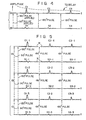
- a plurality of the echo pulse signal series are collected as shown in Figs. 5A, 5B and 5C.
- the echo pulse signal series shown in Fig. 5A is obtained during a first examination period.
- the signal waveforms shown in Figs. 5A, 5B and 5C indicate the quadrature-detected signal waveforms of. the NMR signals
- one echo pulse signal series consists of, e.g., the cos signal components Cl-1, C2-1 and C3-1, as well as the sin signal components Sl-1, S2-1 and S3-1.
- the cos signal components of the echo signal series Cl-1, Cl-2 and Cl-3 that were taken during each examination period are summed each other. That is, the echo signal series are acquried time-sequentially by applying the same exciting pulses to the same slice portion, so that three series of the echo pulse signals are subsequently obtained during three exmaination periods, Cl-1, C2-1, C3-1; Sl-l, S2-1, S3-1: Cl-2, C2-2, C3-2; Sl-2, S2-2, S3-2: Cl-3, C2-3, C3-3; Sl-3, S2-3, S 3-3.
- the cos signal components of the echo signal series e.g., (Cl-1, Cl-2 and Cl-3) are simply summed (i.e., the summing number is three).
- the summing number is three.
- the summed cos signal components (Cl-1, Cl-2 and Cl-3) become approximately three times larger than one of the cos signal components, the randam noises "N” are not multiplied three times. Consequently it can be readily understood that the S/N ratio of the echo signal components is improved by the summation according to this first method.
- both the cos signal components and the sin signal components are processed in the S/N ratio improvement circuit after performing the summation defined by the first method.
- all cos signal componets, or all sin signal components of the echo signal series are summed, e.g., Cl-1, C2-1, C3-1 or Sl-1, S2-1, S3-1 which are collected during the same examination period. That is, for instant, the cos signal components Cl-1, C2-1 and C3-1 taken during one examination period have different amplitudes from each other. Those signal components are merely summed.
- variable is equal to "1" or not (namely, judge whether the present cos signal component is the first one or not). If yes, then clear the buffer memory (not shown) for the cos signal components of the echo signal. If no, sum the present cos signal component by the cos signal component stored in the buffer memory. Then, compare the variable "i" with the number of the echo signal component ("3" in the condition shown in Fig. 5A). If the number is greater than the variable "i", the operation is still continued from the increment step with an increment of the variable "i". When the incremented variable "i" becomes greater than the number of the cos signal component, this processing flow is accomplished. Thereafter the results of the processed signal component are subjected to an examination of the spin density or an arithmetic processing of the relaxation time.
- this processing flow may be applied to not only the remaining cos signal components Cl-2, Cl-3 etc., but also the sin signal components Sl-2, Sl-3 etc. so as improve the S/N ratio thereof.
- the echo signal series as shown in Figs. 5A, 5B and 5C are collected and stored in the adequate memory in advance as same as in the previous methods.
- the former component C2-1 has a line-symmetrical relation with respect to a solid line "X”
- the latter component S2-1 has a point-symmetrical relation with respect to a point "Y”.
- waveform portions of the cos signal component C2-1 which are composed by a front waveform portion C2-1-f and a rear waveform portion C2-I-r are summed with maintaining the above-described line-symmetrical relation.
- the front portion C2-1-f is added to the rear portion C2-1-r by folding the front portion over the rear one with respect to the symmetrical line X, as it were.
- the summed waveform portion is averaged.
- FIG. 8 A flow chart shown in Fig. 8 describes the third method:
- the cos signal component e.g., C2-1 or not.
- the fourth method is one to combine more than two methods which were previously described. That is, there are four combinations that the first and second methods, the second and third methods, the third and first methods, and the first, second and third methods.
- Fig. 9 shows a circuit diagram of an NMR diagnostic apparatus according to one preferred embodiment in which one of the above-described S/N ratio improving method is employed.
- the NMR diagnostic apparatus 100 is comprised of the following components.
- the object 1 such as a patient is arranged in a static magnetic field H o that is produced by an electromagnet (not shown), and simultaneously in a transmitter/receiver coil 2 which is positioned in such a manner that a magnetic field produced by the trasmitter/receiver coil 2 intersects with the static magnetic field H o at a right angle.
- a tuner 3 is connected to the transmitter/receiver coil 2 and has the following function to select an electromagnetic wave having a specific frequency from the electromagnetic waves generated by a transmitter 4 and to be tuned to a specific nuclei, e.g., hydrogen-1 in the object 1 by applying the selective exciting pulse (corresponding to the afore-mentioned the electro- magentic wave having the specific frequency) to the transmitter/receiver coil 2.
- the transmitter 4 is constructed by a standard signal generator 4A (referred to as "SSG") and an RF (radio-frequency) power amplifier 4B.
- the RF signal containing the selective exciting R F pulse signal having e.g., a frequency of 4,258 MHz is generated from the SSG 4A and then amplified in the R F power amplifier 4B to the given power.
- the above-mentioned RF pulse is produced in such a manner that the standard signal generated by SSG 4A is frequency-modulated in a frequency modulator (not shown) by pulse signals from a pulse generator (not shown). Accordingly those frequency modulator and pulse generator constitute an RF pulse generator.
- this RF signal is applied to a reference signal generator 7 (will be described later) as a reference signal.
- a preamplifier 5 is connected to the tuner 3 so as to amplify the NMR signals (the echo pulse signals in this embodiment) which are received through the transmitter/receiver coil 2, and thereafter to apply the amplified echo pulse signals to two phase detectors 6A and 6B respectively.
- Those phase detectors 6A, 6B are designed to operate as the quadrature detector.
- a reference signal generator 7 is comprised of a phase shifter 7A and a 90° phase shifter 7B so as to generate two refrence signals whose phases are different from each other at 90° and which have the same frequency as that of the echo signals. Those reference signals are applied to the phase detectors 6A and 6B respectively.
- the echo signal which has been amplified in the preamplifier 5 is separatedly supplied to those phase detectors 6A and 6B, the echo signal is quadrature-detected therein based upon the two reference signals.
- two detected signals in an analogue form are independently amplified in amplifiers 8A and 8B, and thereafter filtered in low pass filters 9A and 9B so as to eliminate the RF signal components therefrom.
- Those filtered signal waveforms are representetd in Figs. 5A, 5B and SC.
- the filtered analogue signals are converted by A/D converters 10A and 10B into corresponding digital signals.
- Those digitalized signals are input in an S/N ratio improvement circuit 11.
- This circuit 11 has mainly such two functions that the digitalized signals are temporarily stored, and also one of the S/N ratio improving methods as previously described is carried out therein. Subsequently two signals which have been improved with respect to their S/N ratios are supplied to an image processing circuit 12 wherein the spin density and the relaxation time are calculated. Consequently diagnostic information on the object 1 by the nuclear magnetic resonance phenomenon can be obtained which may be displayed on a monitor 13.
- the echo signal series are quadrature-detected with two reference signals which have the frequency identical to the resonant frequency of the NMR signal, and whose phases are different from each other at 90 degrees. Then those quadrature-detected signals are converted into respective digital signals, S/N ratios of which may be improved in the following stage. If those improvd signals are utilized in the NMR diagnostic apparatus, it can be obtained extremely high quality CT images of the object.
- the quadrature detection circuit (7, 6A and 6B) was employed.
- the normal phase detection circuit can be employed.
- one signal detection processing path of the detector 6A - the amplifier 8A - low pass filter 9 - A/D converter 10A, or the detector 6B - the amplifier 8B - low pass filter 9B - A/D converter 10B can be omitted.
- an S/N ratio of the echo pulse signals was improved according to the above-described four methods after performing one of four methods in the S/N improvement circuit 11. It is also possible that the detected NMR signals in an analogue form are directly processed in the S/N ratio improvement circuit 11 in which an analogue memory such as a video tape recorder, or a video disc may be utilized.
- an analogue memory such as a video tape recorder, or a video disc
- the selective exciting pulses such as 90°- ⁇ -180° pulses. It is however, possible to introduce alternatively the normal exciting pulses to excite the slice of the object.
Landscapes
- Health & Medical Sciences (AREA)
- Physics & Mathematics (AREA)
- Life Sciences & Earth Sciences (AREA)
- Nuclear Medicine, Radiotherapy & Molecular Imaging (AREA)
- General Health & Medical Sciences (AREA)
- Radiology & Medical Imaging (AREA)
- Engineering & Computer Science (AREA)
- High Energy & Nuclear Physics (AREA)
- Signal Processing (AREA)
- Medical Informatics (AREA)
- Condensed Matter Physics & Semiconductors (AREA)
- Biophysics (AREA)
- Pathology (AREA)
- Biomedical Technology (AREA)
- Heart & Thoracic Surgery (AREA)
- General Physics & Mathematics (AREA)
- Molecular Biology (AREA)
- Surgery (AREA)
- Animal Behavior & Ethology (AREA)
- Public Health (AREA)
- Veterinary Medicine (AREA)
- Magnetic Resonance Imaging Apparatus (AREA)
Applications Claiming Priority (2)
| Application Number | Priority Date | Filing Date | Title |
|---|---|---|---|
| JP57226972A JPS59119248A (ja) | 1982-12-27 | 1982-12-27 | 核磁気共鳴装置 |
| JP226972/82 | 1982-12-27 |
Publications (3)
| Publication Number | Publication Date |
|---|---|
| EP0114349A2 true EP0114349A2 (fr) | 1984-08-01 |
| EP0114349A3 EP0114349A3 (en) | 1985-05-29 |
| EP0114349B1 EP0114349B1 (fr) | 1988-02-10 |
Family
ID=16853497
Family Applications (1)
| Application Number | Title | Priority Date | Filing Date |
|---|---|---|---|
| EP83112855A Expired EP0114349B1 (fr) | 1982-12-27 | 1983-12-20 | Appareil de diagnostic par résonance magnétique nucléaire |
Country Status (4)
| Country | Link |
|---|---|
| US (1) | US4849886A (fr) |
| EP (1) | EP0114349B1 (fr) |
| JP (1) | JPS59119248A (fr) |
| DE (1) | DE3375670D1 (fr) |
Families Citing this family (5)
| Publication number | Priority date | Publication date | Assignee | Title |
|---|---|---|---|---|
| US4616183A (en) * | 1984-10-22 | 1986-10-07 | General Electric Company | Method for reducing baseline error components in NMR signals |
| US5185573A (en) * | 1991-04-16 | 1993-02-09 | Hewlett-Packard Company | Method for focusing of magnetic resonance images |
| JP4021402B2 (ja) * | 2003-11-11 | 2007-12-12 | 株式会社日立製作所 | 制御可能な検波部を有する核磁気共鳴装置 |
| US7805981B2 (en) * | 2007-02-13 | 2010-10-05 | The Trustees Of The University Of Pennsylvania | Gaseous nuclear symmetric state and quantification thereof |
| JP7152627B2 (ja) * | 2020-02-20 | 2022-10-12 | 日立Astemo株式会社 | 熱式流量計 |
Family Cites Families (16)
| Publication number | Priority date | Publication date | Assignee | Title |
|---|---|---|---|---|
| US3297860A (en) * | 1963-06-19 | 1967-01-10 | Technical Measurement Corp | Spectroscopic computer |
| DE1275629B (de) * | 1964-09-30 | 1968-08-22 | Varian Internat A G | Verfahren zur Befreiung wiederholbarer Spannungsverlaeufe von statistischen Stoerungen und Anordnung zur Durchfuehrung des Verfahrens |
| GB1496886A (en) * | 1974-04-08 | 1978-01-05 | Nat Res Dev | Nuclear magnetic resonance apparatus |
| US4204226A (en) * | 1978-05-16 | 1980-05-20 | Wisconsin Alumni Research Foundation | Real-time digital X-ray time interval difference imaging |
| US4204225A (en) * | 1978-05-16 | 1980-05-20 | Wisconsin Alumni Research Foundation | Real-time digital X-ray subtraction imaging |
| GB1584949A (en) * | 1978-05-25 | 1981-02-18 | Emi Ltd | Imaging systems |
| US4297637A (en) * | 1978-07-20 | 1981-10-27 | The Regents Of The University Of California | Method and apparatus for mapping lines of nuclear density within an object using nuclear magnetic resonance |
| US4250451A (en) * | 1978-12-28 | 1981-02-10 | Cordless Power Corporation | Magnetic induction imaging system |
| US4307344A (en) * | 1979-01-25 | 1981-12-22 | Emi Limited | Imaging systems |
| CA1147807A (fr) * | 1980-03-14 | 1983-06-07 | William A. Edelstein | Methodes de generation de donnees d'images a partir des objets a representer |
| US4493039A (en) * | 1980-05-06 | 1985-01-08 | President And Directors Of Georgetown University | Apparatus and method for image reproduction of materials using their magnetic and electric properties |
| US4430749A (en) * | 1981-06-30 | 1984-02-07 | Siemens Gammasonics, Inc. | Medical imaging apparatus and method for furnishing difference images |
| US4599565A (en) * | 1981-12-15 | 1986-07-08 | The Regents Of The University Of Calif. | Method and apparatus for rapid NMR imaging using multi-dimensional reconstruction techniques |
| US4438400A (en) * | 1982-01-18 | 1984-03-20 | Varian Associates, Inc. | Method for suppression of acoustic ringing in NMR measurements |
| US4468621A (en) * | 1982-01-20 | 1984-08-28 | National Research Development Corporation | Investigation of samples by N.M.R. techniques |
| US4480228A (en) * | 1982-10-15 | 1984-10-30 | General Electric Company | Selective volume method for performing localized NMR spectroscopy |
-
1982
- 1982-12-27 JP JP57226972A patent/JPS59119248A/ja active Granted
-
1983
- 1983-12-20 DE DE8383112855T patent/DE3375670D1/de not_active Expired
- 1983-12-20 EP EP83112855A patent/EP0114349B1/fr not_active Expired
-
1988
- 1988-04-01 US US07/178,850 patent/US4849886A/en not_active Expired - Lifetime
Also Published As
| Publication number | Publication date |
|---|---|
| JPH0370792B2 (fr) | 1991-11-08 |
| EP0114349B1 (fr) | 1988-02-10 |
| US4849886A (en) | 1989-07-18 |
| DE3375670D1 (en) | 1988-03-17 |
| JPS59119248A (ja) | 1984-07-10 |
| EP0114349A3 (en) | 1985-05-29 |
Similar Documents
| Publication | Publication Date | Title |
|---|---|---|
| EP0144871B1 (fr) | Méthode et appareil d'imagerie sélective par RMN de noyaux présentant un déplacement chimique | |
| EP0240319B1 (fr) | Système pour la production d'image par résonance magnétique | |
| US4680546A (en) | Methods of, and pulse sequences for, the supression of undesired resonances by generation of quantum coherence in NMR imaging and spectroscopy | |
| EP0091008B1 (fr) | Méthode de formation d'image RMN en trois dimensions utilisant une excitation sélective | |
| EP0132975B1 (fr) | Méthode et appareil d'imagerie rapide par RMN en utilisant les techniques de reconstruction multi-dimensionnelle | |
| US4879514A (en) | Magnetic resonance imaging device comprising a digital transmitter/receiver | |
| JPH08308810A (ja) | スピン共鳴データの高速取り込み方法及び局所分解検査用のスピン共鳴装置 | |
| US4739266A (en) | MR tomography method and apparatus for performing the method | |
| US4982161A (en) | Multimode magnetic resonance fast imaging method | |
| US20210096202A1 (en) | Dixon mr imaging using a multi-gradient-echo sequence | |
| EP0145277B1 (fr) | Elimination des signaux parasites en résonance magnétique nucléaire | |
| CN103140167A (zh) | 化学物类的磁共振成像 | |
| US4706027A (en) | Method for correcting phase errors in magnetic resonance imaging data | |
| JPS61100645A (ja) | サンプル物体のnmr検査を行なう方法 | |
| US4849886A (en) | System for improving the SIN ratio of a NMR signal by summing in phase cosine and/or sine components | |
| US4878021A (en) | Magnetic resonance spectroscopy studies of restricted volumes | |
| US6005391A (en) | Method for determining the spatial and/or spectral distribution of nuclear magnetization | |
| EP0213614A2 (fr) | Procédé pour obtenir des données de résonance magnétique nucléaire | |
| US5015956A (en) | Magnetic resonance tomography method for determining the nuclear magnetization in a number of parallel slices | |
| US5081417A (en) | 2-quantum selective mr sequence for selectively determining a nuclear magnetisation distribution of a metabolite | |
| JPH04354932A (ja) | 磁気共鳴分光装置 | |
| JP3402647B2 (ja) | 磁気共鳴映像装置 | |
| JP3137380B2 (ja) | 磁気共鳴イメージング装置 | |
| JPH03231632A (ja) | 磁気共鳴イメージング方法 | |
| EP0109517A2 (fr) | Appareil de diagnostic par résonance magnétique nucléaire |
Legal Events
| Date | Code | Title | Description |
|---|---|---|---|
| PUAI | Public reference made under article 153(3) epc to a published international application that has entered the european phase |
Free format text: ORIGINAL CODE: 0009012 |
|
| 17P | Request for examination filed |
Effective date: 19840117 |
|
| AK | Designated contracting states |
Designated state(s): DE FR GB NL |
|
| RAP1 | Party data changed (applicant data changed or rights of an application transferred) |
Owner name: KABUSHIKI KAISHA TOSHIBA |
|
| PUAL | Search report despatched |
Free format text: ORIGINAL CODE: 0009013 |
|
| AK | Designated contracting states |
Designated state(s): DE FR GB NL |
|
| 17Q | First examination report despatched |
Effective date: 19860911 |
|
| GRAA | (expected) grant |
Free format text: ORIGINAL CODE: 0009210 |
|
| AK | Designated contracting states |
Kind code of ref document: B1 Designated state(s): DE FR GB NL |
|
| REF | Corresponds to: |
Ref document number: 3375670 Country of ref document: DE Date of ref document: 19880317 |
|
| ET | Fr: translation filed | ||
| PLBI | Opposition filed |
Free format text: ORIGINAL CODE: 0009260 |
|
| 26 | Opposition filed |
Opponent name: N.V. PHILIPS' GLOEILAMPENFABRIEKEN Effective date: 19881110 |
|
| NLR1 | Nl: opposition has been filed with the epo |
Opponent name: N.V. PHILIPS K GLOEILAMPENFABRIEKEN |
|
| PGFP | Annual fee paid to national office [announced via postgrant information from national office to epo] |
Ref country code: FR Payment date: 19931209 Year of fee payment: 11 |
|
| PGFP | Annual fee paid to national office [announced via postgrant information from national office to epo] |
Ref country code: DE Payment date: 19931227 Year of fee payment: 11 |
|
| RDAG | Patent revoked |
Free format text: ORIGINAL CODE: 0009271 |
|
| STAA | Information on the status of an ep patent application or granted ep patent |
Free format text: STATUS: PATENT REVOKED |
|
| PGFP | Annual fee paid to national office [announced via postgrant information from national office to epo] |
Ref country code: GB Payment date: 19941212 Year of fee payment: 12 |
|
| PGFP | Annual fee paid to national office [announced via postgrant information from national office to epo] |
Ref country code: NL Payment date: 19941231 Year of fee payment: 12 |
|
| 27W | Patent revoked |
Effective date: 19941013 |
|
| GBPR | Gb: patent revoked under art. 102 of the ep convention designating the uk as contracting state |
Free format text: 941013 |
|
| NLR2 | Nl: decision of opposition | ||
| APAH | Appeal reference modified |
Free format text: ORIGINAL CODE: EPIDOSCREFNO |