EP0114547A2 - Akustische Anordnung mit parametrischen Mehrfachbündelantennen - Google Patents
Akustische Anordnung mit parametrischen Mehrfachbündelantennen Download PDFInfo
- Publication number
- EP0114547A2 EP0114547A2 EP83402406A EP83402406A EP0114547A2 EP 0114547 A2 EP0114547 A2 EP 0114547A2 EP 83402406 A EP83402406 A EP 83402406A EP 83402406 A EP83402406 A EP 83402406A EP 0114547 A2 EP0114547 A2 EP 0114547A2
- Authority
- EP
- European Patent Office
- Prior art keywords
- frequencies
- signals
- channels
- antenna
- emission
- Prior art date
- Legal status (The legal status is an assumption and is not a legal conclusion. Google has not performed a legal analysis and makes no representation as to the accuracy of the status listed.)
- Withdrawn
Links
Images


Classifications
-
- G—PHYSICS
- G01—MEASURING; TESTING
- G01S—RADIO DIRECTION-FINDING; RADIO NAVIGATION; DETERMINING DISTANCE OR VELOCITY BY USE OF RADIO WAVES; LOCATING OR PRESENCE-DETECTING BY USE OF THE REFLECTION OR RERADIATION OF RADIO WAVES; ANALOGOUS ARRANGEMENTS USING OTHER WAVES
- G01S15/00—Systems using the reflection or reradiation of acoustic waves, e.g. sonar systems
- G01S15/02—Systems using the reflection or reradiation of acoustic waves, e.g. sonar systems using reflection of acoustic waves
-
- G—PHYSICS
- G10—MUSICAL INSTRUMENTS; ACOUSTICS
- G10K—SOUND-PRODUCING DEVICES; METHODS OR DEVICES FOR PROTECTING AGAINST, OR FOR DAMPING, NOISE OR OTHER ACOUSTIC WAVES IN GENERAL; ACOUSTICS NOT OTHERWISE PROVIDED FOR
- G10K11/00—Methods or devices for transmitting, conducting or directing sound in general; Methods or devices for protecting against, or for damping, noise or other acoustic waves in general
- G10K11/18—Methods or devices for transmitting, conducting or directing sound
- G10K11/26—Sound-focusing or directing, e.g. scanning
- G10K11/34—Sound-focusing or directing, e.g. scanning using electrical steering of transducer arrays, e.g. beam steering
- G10K11/341—Circuits therefor
- G10K11/343—Circuits therefor using frequency variation or different frequencies
-
- G—PHYSICS
- G01—MEASURING; TESTING
- G01N—INVESTIGATING OR ANALYSING MATERIALS BY DETERMINING THEIR CHEMICAL OR PHYSICAL PROPERTIES
- G01N2291/00—Indexing codes associated with group G01N29/00
- G01N2291/02—Indexing codes associated with the analysed material
- G01N2291/024—Mixtures
- G01N2291/02491—Materials with nonlinear acoustic properties
Definitions
- the object of the present invention is a multibeam acoustic sounder using the non-linear properties of the marine environment.
- Knowledge of the precise bathymetry of the ocean floor is and will be increasingly obtained using so-called multibeam sounders.
- These sounders have the property, although they are directive, to cover a significant area of ground on the bottom, which compared to conventional single-beam sounders, considerably increases the coverage rate and therefore the efficiency of the carrier boat. For example, an area of 10km x 10km with funds of 4300m will be covered at 10 knots, in about 1 hour with a multibeam echosounder having 15 beams of 3 °, while the same will be probed in 15 hours with a single-beam echosounder identical.
- This covered area is obtained for example by formation of directional beams in reception by a technique known in the field of sonars.
- the present invention has the advantage over the prior art of making it possible to produce a depth sounder with antenna dimensions less than 1 meter, thanks to the use of a parametric antenna. Thanks to this reduced size, installation and maintenance costs are reduced and it becomes possible to install it on small vessels. It is also possible to use the same antennas by directly exploiting the high frequency signals for a shallow depth sounder.
- This parametric antenna can be mounted in the hull of the ship or in a "fish" towed away from the ship's noise sounder.
- the non-linear properties of the medium mean that the speed of this wave depends on the instantaneous amplitude of the sound pressure, the sinusoidal shape of this pressure is deformed to tend towards a shape serrated.
- the antenna which radiates this low frequency f 1 is therefore not the antenna, or transducer, fixed under the boat but the entire volume "insonified" by the two primary frequencies.
- This elongated antenna, made of water, radiates its low frequency in the direction of propagation of the primary waves.
- FIG. 1 shows a schematic view of the depth sounder according to the invention.
- the transmitting antenna transmits simultaneously at the primary frequencies F O and F i , which generates by non-linear effects the beam f . at the difference frequency.
- the intersection of the different beams with the background has been shown with shading.
- These different emission beams are obtained successively by changing the primary frequencies F i and by forming angular paths on emission.
- each secondary frequency f i is used twice and two reception channels R 1 and R 2 are formed .
- We chose a preferential order for the n beams f 1 , f 2 , ... f 8 (n 8) for the two channels in order to obtain good separation on reception.
- the lowest secondary frequencies are used for the most angularly spaced beams to minimize the losses.
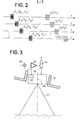
- Figure 2 shows an example of the transmit-receive time diagrams for different signals.
- a transmission E 1 takes place at the primary frequencies, F 0 and Flet the reception of the echo r 1 is received at the secondary frequency f 1 .
- the emission E 2 at the primary frequencies F 0 , F 2 is offset from the secondary emission E 1 and the echo is received at the frequency f 2 .
- the transmissions are restarted to form the set of beams shown in FIG. 1.
- the figure also shows the echoes r 1 , r 2 , ... r n at the frequencies f 1 , f 2 , ... f n .
- 8 frequencies can be used for transmission and 2 channels preformed for reception.
- the transmitting frequencies can be constituted by a known carrier frequency within the reception band.
- the reception bands are 200 to 300 Hz.
- a total spectral congestion of 300 x 8 2400 Hz to be placed in the band 8 - 10, 5 KHz.
- the higher frequencies will preferably be chosen for the beams near the vertical (the higher absorption losses are compensated by a shorter path in the medium).
- Table 1 and Figure 1 give an example of the frequency distribution on the intercept to be covered.
- the beams in emission and in reception are stabilized This has the advantage of concentrating all the energy in the useful zone and not of spreading it out and covering all the required intercept, whatever the movements of the carrier, and of facilitating the real-time exploitation of the noted.
- each elementary sensor constituting the emission transducer can be supplied by a signal, the phase of which is calculated at any time, so that the complete diagram of the antenna radiates in a fixed direction in space.
- This phase calculation is obtained from the roll and pitch angles measured on the carrier by a vertical unit. This realization remains relatively expensive because of the high number of sensors.
- each source at a distance of X / 2 from the previous one (spacing required not to generate parasitic image lobes at the pump frequencies) it will take about 1000 to 1200 elementary sensors therefore as many phase generators and transmitters.
- the sensors are grouped into elementary columns and these columns are supplied with phases calculated as a function of the roll angle.
- the acoustic base 32 mounted around an axis of rotation 30 in the shell 31 is controlled by a servo consisting of a jack 34, a control amplifier 35, a circuit 36 and an inclinometer 33.
- the purpose of the control of the beams 37 is to permanently maintain the transducers in a horizontal position.
- coherent processing is used. Indeed the conventional sounders give a sound level of 125dB for 6000m deep for an emitted power of a few kilowatts. If we use a coherent treatment with a product B x T (emission time band) of 300, we can compensate loss of non-linear conversions. The bandwidth being fixed at 300 Hz for example, the transmission time will be 1000 ms for each of the beams. To achieve this function, known circuits such as digital correlators, surface waves or charge transfer devices will be used on reception.
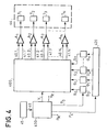
- a processor 430 controls the sequences of the pulses to be transmitted and the phase shifters of the signals for the formation of transmission channels by the assembly 400.
- the processor also receives the value of the roll 46 measured by a measuring device 45.
- the device comprises a generator G 0 at the frequency F 0 as well as the n generators G 1 , G 2 , ... G n .
- the processor triggers at P 0 the pulses of the generator G 0 as well as the successive sequences of the generators G 1 , G 2 , ... G n at P i , by means of the code modulator 420.
- These codes are known codes used for doing pulse compression for example frequency modulation codes.
- the signals S 0 , S 1 , S 2 , ... S n supplied by these generators G 0 , G 1 , G 2 , ... G n are applied to the channel forming circuits 400 receiving the control signals in V phase shifts.
- the transmitting antenna 44 comprises N columns of transducers T 1 , T 2 , ... T N parallel to the axis of the boat supplied by the summing amplifiers A 1 , A 2 , ... A N.
- the amplifier A 1 receives the phase shifted signals 40.1 and 41.1.
- the signal 40.1 corresponds to the frequency F 0 and the signal 41.1 to the frequency F i . It is the same for the other signals applied to the amplifiers A 2 ... A N.
- FIG. 5 shows the receiving device.
- the reception antenna A R comprises m columns of transducers t 1 , t 2 ... t m .
- the number is much smaller than the number N of transducer columns of the transmitting antenna 44.
- the columns are parallel to the axis of the boat.
- the signals received by the columns of reception transducers t l , t 2 ... t m are applied to gain amplifiers controlled as a function of the depth 5.1, 5.2, ... 5.m.
- the control signal P R being supplied by the processor 430, as well as the channel formation signals VR taking account of the roll.
- Amplified signals are applied to the channel formation circuit at reception 500 which provides for example two channels V R1 , V R2 . These two channels are applied to filters 510 centered on the frequencies f 1 , f 2 , ... f n .
- signals 50.11 and 50.12 corresponding to the frequency f i are obtained for the two reception channels and likewise for the other frequencies. These signals are applied to known coherent processing circuits 520 and to known detection circuits 530. Thus for the frequency f l , the processed signals 51.11 and 51.12 and the detected signals 52.11 and 52.12 are obtained.
- the 2n channels 52.11, 52.12, 52.21, 52.22, 52.31, 52.32, ... 52.nl, 52.n2 are obtained.
- the invention can be applied to a fish towed 100 or 200m behind the boat and submerged at 50m to escape on the one hand from the movements of the surface, and on the other hand from the noises of the carrier.
- the transmit-receive antenna A ER is placed , the amplifiers and the channels forming circuits 66 and 67.
- the processing unit 65 communicating with the fish by a multiplexed signal.
Landscapes
- Physics & Mathematics (AREA)
- Engineering & Computer Science (AREA)
- Acoustics & Sound (AREA)
- Radar, Positioning & Navigation (AREA)
- Remote Sensing (AREA)
- Multimedia (AREA)
- Computer Networks & Wireless Communication (AREA)
- General Physics & Mathematics (AREA)
- Measurement Of Velocity Or Position Using Acoustic Or Ultrasonic Waves (AREA)
Applications Claiming Priority (2)
| Application Number | Priority Date | Filing Date | Title |
|---|---|---|---|
| FR8221228 | 1982-12-17 | ||
| FR8221228A FR2538124B1 (fr) | 1982-12-17 | 1982-12-17 | Systeme acoustique a antennes parametriques multifaisceaux |
Publications (2)
| Publication Number | Publication Date |
|---|---|
| EP0114547A2 true EP0114547A2 (de) | 1984-08-01 |
| EP0114547A3 EP0114547A3 (de) | 1984-08-08 |
Family
ID=9280235
Family Applications (1)
| Application Number | Title | Priority Date | Filing Date |
|---|---|---|---|
| EP83402406A Withdrawn EP0114547A3 (de) | 1982-12-17 | 1983-12-13 | Akustische Anordnung mit parametrischen Mehrfachbündelantennen |
Country Status (3)
| Country | Link |
|---|---|
| EP (1) | EP0114547A3 (de) |
| FI (1) | FI834639A7 (de) |
| FR (1) | FR2538124B1 (de) |
Cited By (3)
| Publication number | Priority date | Publication date | Assignee | Title |
|---|---|---|---|---|
| EP0424239A1 (de) * | 1989-10-20 | 1991-04-24 | Thomson-Csf | Strahlbündelungsverfahren fÀ¼r Sonar |
| GB2493277A (en) * | 2011-07-25 | 2013-01-30 | Bosch Gmbh Robert | Determining the size and position of objects using ultrasound |
| RU2582897C2 (ru) * | 2014-04-14 | 2016-04-27 | Общество с ограниченной ответственностью "Морские Инновации" | Излучающий тракт параметрического гидролокатора |
Families Citing this family (2)
| Publication number | Priority date | Publication date | Assignee | Title |
|---|---|---|---|---|
| RU187455U1 (ru) * | 2018-12-27 | 2019-03-06 | Общество с ограниченной ответственностью "Маринн 3Д" | Многочастотный эхолот-профилограф |
| PL445508A1 (pl) * | 2023-07-06 | 2024-07-29 | Borucka Ewa | System do wykonywania pomiarów hydrograficznych oraz sposób wykonywania pomiarów hydrograficznych |
Family Cites Families (4)
| Publication number | Priority date | Publication date | Assignee | Title |
|---|---|---|---|---|
| GB1360901A (en) * | 1971-02-01 | 1974-07-24 | Raytheon Co | Communication system utilizing a dispersive transmission medium |
| US3824531A (en) * | 1973-01-15 | 1974-07-16 | Raytheon Co | Plural beam steering system |
| GB1486068A (en) * | 1974-03-28 | 1977-09-14 | Simrad As | Echo sounder systems utilizing non-linear acoustic signal interaction |
| DE3113261A1 (de) * | 1981-04-02 | 1982-10-21 | Fried. Krupp Gmbh, 4300 Essen | "echolot" |
-
1982
- 1982-12-17 FR FR8221228A patent/FR2538124B1/fr not_active Expired
-
1983
- 1983-12-13 EP EP83402406A patent/EP0114547A3/de not_active Withdrawn
- 1983-12-16 FI FI834639A patent/FI834639A7/fi not_active Application Discontinuation
Cited By (5)
| Publication number | Priority date | Publication date | Assignee | Title |
|---|---|---|---|---|
| EP0424239A1 (de) * | 1989-10-20 | 1991-04-24 | Thomson-Csf | Strahlbündelungsverfahren fÀ¼r Sonar |
| FR2653564A1 (fr) * | 1989-10-20 | 1991-04-26 | Thomson Csf | Procede de formation de voies pour sonar. |
| US5101383A (en) * | 1989-10-20 | 1992-03-31 | Thomson-Csf | Method for the formation of channels for sonar |
| GB2493277A (en) * | 2011-07-25 | 2013-01-30 | Bosch Gmbh Robert | Determining the size and position of objects using ultrasound |
| RU2582897C2 (ru) * | 2014-04-14 | 2016-04-27 | Общество с ограниченной ответственностью "Морские Инновации" | Излучающий тракт параметрического гидролокатора |
Also Published As
| Publication number | Publication date |
|---|---|
| EP0114547A3 (de) | 1984-08-08 |
| FR2538124B1 (fr) | 1986-02-07 |
| FI834639L (fi) | 1984-06-18 |
| FR2538124A1 (fr) | 1984-06-22 |
| FI834639A0 (fi) | 1983-12-16 |
| FI834639A7 (fi) | 1984-06-18 |
Similar Documents
| Publication | Publication Date | Title |
|---|---|---|
| EP0107552B1 (de) | Interferometrisches Sonargerät durch Anwendung nichtlinearer akustischer Eigenschaften | |
| CA1195417A (fr) | Sonar | |
| EP0397547A1 (de) | Vermeidungssonar für Unterwasserobjekte unterhalb der Wasseroberfläche | |
| CN114167427A (zh) | 一种多频段三维探掩埋物声呐装置及方法 | |
| FR2688894A1 (fr) | Sonar lateral rapide a faisceaux multiples comportant peu d'elements et procede pour sa mise en óoeuvre. | |
| EP0342093A1 (de) | Verfahren zur Klassifizierung von Untersee-Gegenständen, insbesondere für Ankerminen | |
| EP0114547A2 (de) | Akustische Anordnung mit parametrischen Mehrfachbündelantennen | |
| EP1407292B1 (de) | Bilderzeugungs- sonar und detektionssytem mit verwendung eines solchen sonars | |
| WO1990009600A1 (fr) | Procede pour augmenter la cadence image d'un sonar et sonar pour la mise en ×uvre de ce procede | |
| RU2460088C1 (ru) | Способ обнаружения локального объекта на фоне распределенной помехи | |
| EP0688437B1 (de) | Vorrichtung zum aufspüren im boden eingebetteter objekte | |
| RU2721307C1 (ru) | Акустический способ и устройство измерения параметров морского волнения | |
| FR2685781A1 (fr) | Sonar d'evitement d'objets en pleine eau pour batiment de surface. | |
| US20210018619A1 (en) | Multiple Frequency Side-Scan Sonar | |
| JPS6144382A (ja) | アクテイブソ−ナ−装置 | |
| Ellis et al. | Comparison of range-dependent reverberation model predictions with array data from the 2013 Target and Reverberation Experiment | |
| Babb | Feasibility of interferometric swath bathymetry using GLORIA, a long-range sidescan | |
| Ellis et al. | A look at reverberation and target echo on a vertical array during the Target and Reverberation Experiment | |
| WO2020083838A1 (fr) | Procede d'utilisation d'un sonar actif a large bande spectrale d'emission et systeme sonar | |
| WO2002075362A1 (fr) | Imageur acoustique d'objets enfouis | |
| EP0593532B1 (de) | System für exploration des meeresbodens | |
| JPH0239754B2 (de) | ||
| Sutton | A tutorial on underwater acoustic imaging | |
| WO2023031553A1 (fr) | Dispositif et procédé de détection et localisation d'objets immergés | |
| FR2735873A1 (fr) | Procede de mesure de vitesse a l'aide d'un loch doppler a precision amelioree |
Legal Events
| Date | Code | Title | Description |
|---|---|---|---|
| PUAI | Public reference made under article 153(3) epc to a published international application that has entered the european phase |
Free format text: ORIGINAL CODE: 0009012 |
|
| PUAL | Search report despatched |
Free format text: ORIGINAL CODE: 0009013 |
|
| AK | Designated contracting states |
Designated state(s): DE GB |
|
| AK | Designated contracting states |
Designated state(s): DE GB |
|
| 17P | Request for examination filed |
Effective date: 19850118 |
|
| 17Q | First examination report despatched |
Effective date: 19860129 |
|
| R17C | First examination report despatched (corrected) |
Effective date: 19860623 |
|
| STAA | Information on the status of an ep patent application or granted ep patent |
Free format text: STATUS: THE APPLICATION HAS BEEN WITHDRAWN |
|
| 18W | Application withdrawn |
Withdrawal date: 19860919 |
|
| RIN1 | Information on inventor provided before grant (corrected) |
Inventor name: NALEWAJK, WLADYSLAW Inventor name: PEYNAUD, FRANCOIS |