EP0114571A2 - Dispositif de boudinage avec remontée de matière d'un profil creux - Google Patents
Dispositif de boudinage avec remontée de matière d'un profil creux Download PDFInfo
- Publication number
- EP0114571A2 EP0114571A2 EP83810592A EP83810592A EP0114571A2 EP 0114571 A2 EP0114571 A2 EP 0114571A2 EP 83810592 A EP83810592 A EP 83810592A EP 83810592 A EP83810592 A EP 83810592A EP 0114571 A2 EP0114571 A2 EP 0114571A2
- Authority
- EP
- European Patent Office
- Prior art keywords
- die
- cavern
- molded
- section
- molding
- Prior art date
- Legal status (The legal status is an assumption and is not a legal conclusion. Google has not performed a legal analysis and makes no representation as to the accuracy of the status listed.)
- Ceased
Links
Images


Classifications
-
- B—PERFORMING OPERATIONS; TRANSPORTING
- B21—MECHANICAL METAL-WORKING WITHOUT ESSENTIALLY REMOVING MATERIAL; PUNCHING METAL
- B21C—MANUFACTURE OF METAL SHEETS, WIRE, RODS, TUBES, PROFILES OR LIKE SEMI-MANUFACTURED PRODUCTS OTHERWISE THAN BY ROLLING; AUXILIARY OPERATIONS USED IN CONNECTION WITH METAL-WORKING WITHOUT ESSENTIALLY REMOVING MATERIAL
- B21C23/00—Extruding metal; Impact extrusion
- B21C23/21—Presses specially adapted for extruding metal
- B21C23/218—Indirect extrusion presses
-
- B—PERFORMING OPERATIONS; TRANSPORTING
- B21—MECHANICAL METAL-WORKING WITHOUT ESSENTIALLY REMOVING MATERIAL; PUNCHING METAL
- B21C—MANUFACTURE OF METAL SHEETS, WIRE, RODS, TUBES, PROFILES OR LIKE SEMI-MANUFACTURED PRODUCTS OTHERWISE THAN BY ROLLING; AUXILIARY OPERATIONS USED IN CONNECTION WITH METAL-WORKING WITHOUT ESSENTIALLY REMOVING MATERIAL
- B21C23/00—Extruding metal; Impact extrusion
- B21C23/02—Making uncoated products
- B21C23/20—Making uncoated products by backward extrusion
- B21C23/205—Making products of generally elongated shape
-
- B—PERFORMING OPERATIONS; TRANSPORTING
- B21—MECHANICAL METAL-WORKING WITHOUT ESSENTIALLY REMOVING MATERIAL; PUNCHING METAL
- B21C—MANUFACTURE OF METAL SHEETS, WIRE, RODS, TUBES, PROFILES OR LIKE SEMI-MANUFACTURED PRODUCTS OTHERWISE THAN BY ROLLING; AUXILIARY OPERATIONS USED IN CONNECTION WITH METAL-WORKING WITHOUT ESSENTIALLY REMOVING MATERIAL
- B21C25/00—Profiling tools for metal extruding
- B21C25/02—Dies
Definitions
- the invention relates to a device for the indirect extrusion of a hollow profile from a bolt, in particular an aluminum hollow bolt, which is fed from a pressure die to a shaping cross section of a die, the die being provided so that it can be driven over by a block receiver, and its shaping cross section is assigned a mandrel which determines the inner contour of the hollow profile is.
- the block enclosed by the recipient or receiver is usually pressed directly by means of the press ram of a hydraulic press through the stationary shaping die; here the press ram or a press disk attached to it forms the abutment for the material to be pressed.
- the press ram or a press disk attached to it forms the abutment for the material to be pressed.
- either the shaping tool, the die is inserted into the fixed block receiver or it is movable and can be moved over the die. In both cases, a new block or bolt is inserted into the block receiver and pressed up to the abutment before pressing.
- the tool sits on a long - - thermally and mechanically highly stressed - ram; this must be hollow, since the shaped strand is passed through it.
- the entire press forces act on the press ram in the course of the pressing, mostly also - in addition to the pure compressive forces - torsional and bending stresses.
- the mandrel also protrudes into the press ram
- the inventor has set itself the goal of producing a hollow profile with a flange attached in one piece in a cost-effective manner by means of indirect extrusion and of creating a device therefor.
- the molding cross-section in the pressing direction is directly preceded by a molding cavern, the radial extent of which is greater than the width of the mold cross-section and in which the flange projecting laterally over the hollow profile is formed from the pressed matrix.
- this molded cavern is formed by a ring collar and a molded lining.
- the molded cavern is thus a molded box for the flange, which has a round, oval or - preferably - a square outline.
- the flange tube can be removed from the side, which allows relatively large lengths of tube.
- the contours of the molded cavern determine the shape of the flange, it is also possible, for example, to design it with ring ribs or the like if there are corresponding grooves in the cavern floor.
- a block receiver 3 for carrying out the so-called. Indirect extrusion process arranged separately, which, thanks to its - to the main axis E of the extruder 2 - axial bore 4 is guided via a fixed ram 5. The latter is supported with a clamping head 6 directly on the crosshead 1.
- An axial punch channel 7 runs in the press punch 5 and extends from a shaping die 10 (not clearly emphasized in FIG. 1) to a through opening 9 in the crosshead 1. From the press ram 5 held by a slide 11, the block receiver 3 can be pulled against the pressing direction x.
- a press cylinder 14 in indicated his stand 15; From the press cylinder 14, a pressure ram 16 - and a mandrel 17 - protrudes from the press axis E.
- the distance a between the cylinder-side transducer front 13 and the end of the mandrel 17 in the rest position of the extruder 2 shown in FIG. 1 is dimensioned such that in this rest position a hollow bolt B made of light metal can be placed in front of the press ram 5 by a loading carriage 18; If the pin axis is coaxial to the press axis E, the pin B can be pressed by the pressure stamp 16 in the pressing direction x.
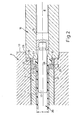
- Fig. 2 shows the production of a hollow profile 20 from a tubular part 21 of an outer diameter t and a flange 22 of a height i.
- the bolt B With the pressure face 25 of the pressure stamp 16, the bolt B is pressed against the die 10, which is provided with a shaping cross section 24. Its ring-like wall 26 determines the outer contour of the tube piece 21, the inner contour of which produces the mandrel 17 projecting into the shaping cross section 25.
- the die opening is preceded by a cavity 30 in the pressing direction x, in which that flange 22 is formed at the end of the pressing process.
- the pressure face 24 of the pressure stamp 16 has reached the die front 12; an annular stop shoulder 28 of the pressure stamp 16 then projects into a stop recess 29 of the block receiver 3.
- Fig. 2 it can also be seen that the mandrel 17 is mounted in a mandrel channel 19 of the plunger 16.
- the mold cavern 30 can be seen in the pressure stamp 16; it is formed by an annular projection 32 of the pressure stamp 16 and a molded chuck 33 which is seated on the mandrel 17.
- the projection ring 32 is provided with a stop molding 35 which, in the end position shown, receives the ring edge 36 around the sensor bore 4.
- flange tubes 20 in one piece, which can be used, for example, as recipients for centrifuges of uranium separation systems.
- the device for solution annealing of the bolt B is not shown in the drawing.
Landscapes
- Engineering & Computer Science (AREA)
- Mechanical Engineering (AREA)
- Extrusion Of Metal (AREA)
Applications Claiming Priority (2)
| Application Number | Priority Date | Filing Date | Title |
|---|---|---|---|
| DE8236460U | 1982-12-24 | ||
| DE8236460 | 1982-12-24 |
Publications (2)
| Publication Number | Publication Date |
|---|---|
| EP0114571A2 true EP0114571A2 (fr) | 1984-08-01 |
| EP0114571A3 EP0114571A3 (fr) | 1984-10-10 |
Family
ID=6746895
Family Applications (1)
| Application Number | Title | Priority Date | Filing Date |
|---|---|---|---|
| EP83810592A Ceased EP0114571A3 (fr) | 1982-12-24 | 1983-12-14 | Dispositif de boudinage avec remontée de matière d'un profil creux |
Country Status (2)
| Country | Link |
|---|---|
| US (1) | US4557131A (fr) |
| EP (1) | EP0114571A3 (fr) |
Cited By (2)
| Publication number | Priority date | Publication date | Assignee | Title |
|---|---|---|---|---|
| EP0182911A4 (fr) * | 1984-04-20 | 1986-08-21 | Kobe Steel Ltd | Procede et dispositif d'extrusion indirecte. |
| CN102114497B (zh) * | 2009-12-30 | 2012-11-28 | 沈阳中复科金压力容器有限公司 | 铝合金无缝气瓶异形挤压凹模 |
Families Citing this family (7)
| Publication number | Priority date | Publication date | Assignee | Title |
|---|---|---|---|---|
| US4631945A (en) * | 1985-11-22 | 1986-12-30 | Traco | Billet lubrication apparatus |
| FR2750901B1 (fr) * | 1996-07-11 | 1998-11-06 | Clecim Sa | Procede de deblocage d'une billette dans une presse a filer |
| US6931904B2 (en) | 2003-10-27 | 2005-08-23 | American Axle & Manufacturing, Inc. | Method of forming a trailer receiver tube using hollow forward extrusion |
| WO2009006572A1 (fr) * | 2007-07-05 | 2009-01-08 | Alcoa Inc. | Corps métalliques contenant des microcavités et appareil et procédés connexes |
| CN101332476B (zh) * | 2008-08-01 | 2010-06-02 | 河南科技大学 | 一种薄壁长管形零件坯料的精密挤压成形方法及专用模具 |
| US20100143527A1 (en) * | 2008-12-17 | 2010-06-10 | Manu Mathai | Extrusion die and method for extruding a rotor shaft for a wind turbine generator |
| USD794823S1 (en) | 2010-08-24 | 2017-08-15 | Life Technologies Corporation | Electrophoresis tank with a base and cassette inserted in |
Family Cites Families (14)
| Publication number | Priority date | Publication date | Assignee | Title |
|---|---|---|---|---|
| US362623A (en) * | 1887-05-10 | Chables b | ||
| US2278293A (en) * | 1941-04-16 | 1942-03-31 | William J Watson | Forging apparatus |
| US2371041A (en) * | 1942-01-09 | 1945-03-06 | Hydraulic Dev Corp Inc | Method of and device for forging |
| DE926482C (de) * | 1949-11-09 | 1955-04-18 | Gewerkschaft Reuss | Verfahren zur Herstellung von aus einem Stueck bestehenden nahtlosen Leichtmetallrohren mit Bunden |
| US2893553A (en) * | 1951-12-27 | 1959-07-07 | Kreidler Alfred | Apparatus for the production of hollow metallic articles |
| US2860775A (en) * | 1954-10-05 | 1958-11-18 | Charles A Brauchler | Split die and container for extrusion press |
| US3150773A (en) * | 1963-01-04 | 1964-09-29 | American Metal Climax Inc | Material forming process and apparatus |
| US3355927A (en) * | 1964-03-05 | 1967-12-05 | Baldwin Lima Hamilton Corp | Extrusion press for multiple tube configurations and the like |
| DE1938024A1 (de) * | 1969-07-26 | 1971-02-04 | Karl Gartner | Strangpresse zur Herstellung von Leichtmetallprofilen |
| DE2419709B2 (de) * | 1974-04-24 | 1976-09-02 | Schloemann-Siemag AG, 4000 Düsseldorf | Presstempelhalterung an einer metallstrangpresse |
| DE2509490C3 (de) * | 1975-03-05 | 1980-10-02 | Schloemann-Siemag Ag, 4000 Duesseldorf | Verschlußstück an einer Indirekt-Metallstrangpresse für Leicht- und Schwermetall |
| DE2511295A1 (de) * | 1975-03-14 | 1976-09-23 | Aluminium Walzwerke Singen | Verfahren zum indirekten strangpressen sowie vorrichtung zur durchfuehrung des verfahrens |
| NL173828C (nl) * | 1978-09-28 | 1984-03-16 | Schelde Nv | Inrichting voor het door extrusie vervaardigen van een flens-pijp-constructie. |
| JPS5668524A (en) * | 1979-11-06 | 1981-06-09 | Ryobi Ltd | Production of spike mounting seat |
-
1983
- 1983-12-14 EP EP83810592A patent/EP0114571A3/fr not_active Ceased
- 1983-12-20 US US06/563,309 patent/US4557131A/en not_active Expired - Fee Related
Cited By (3)
| Publication number | Priority date | Publication date | Assignee | Title |
|---|---|---|---|---|
| EP0182911A4 (fr) * | 1984-04-20 | 1986-08-21 | Kobe Steel Ltd | Procede et dispositif d'extrusion indirecte. |
| US4744236A (en) * | 1984-04-20 | 1988-05-17 | Kabushiki Kaisha Kobeseikosho | Method of and apparatus for indirect extrusion |
| CN102114497B (zh) * | 2009-12-30 | 2012-11-28 | 沈阳中复科金压力容器有限公司 | 铝合金无缝气瓶异形挤压凹模 |
Also Published As
| Publication number | Publication date |
|---|---|
| US4557131A (en) | 1985-12-10 |
| EP0114571A3 (fr) | 1984-10-10 |
Similar Documents
| Publication | Publication Date | Title |
|---|---|---|
| DE2747382C2 (de) | Verfahren zur Herstellung eines einen hohlzylindrischen Teil aufweisenden Flanschstückes und Vorrichtung zur Durchführung des Verfahrens | |
| DE1602394B1 (de) | Verfahren und einrichtung zur umformung eines langgestreckten hohlen rohlings | |
| EP0347369A2 (fr) | Procédé et dispositif d'élargissement hydraulique de profils creux | |
| DE3824699C2 (de) | Verfahren zum Herstellen eines rotationssymmetrischen Hohlkörpers mit einer durchgehenden, axial sich erstreckenden zentralen Öffnung und einer umlaufenden, nutenförmigen Einschnürung in der Außenfläche durch spanlose Umformung eines massiven zylindrichen Rohlings | |
| EP0114571A2 (fr) | Dispositif de boudinage avec remontée de matière d'un profil creux | |
| EP0114570B1 (fr) | Dispositif de boudinage d'un profil creux | |
| EP0649689B1 (fr) | Méthode et dispositif pour la fabrication des raccords à compression | |
| EP0183278B1 (fr) | Procédé et dispositif pour fabrication de tuyau en matière plastique longue par moulage par injection | |
| EP0941780B1 (fr) | Méthode et dispositif pour former les corps creux avec des renflements de distance en distance | |
| DE69419206T2 (de) | Verfahren und Vorrichtung zum Herstellen eines metallischen Teils | |
| DE102005049369B4 (de) | Verfahren zur Herstellung feinkörniger, polykristalliner Werkstoffe oder Werkstücke sowie Strangpressanlage | |
| EP0043025B1 (fr) | Presse pour le filage indirect de métaux et appareil pour enlever des billettes "gelées" | |
| DE3812740C2 (fr) | ||
| EP1203623B1 (fr) | Procédé d'extrusion de profilés tubulaires | |
| DE2123528A1 (de) | Vorrichtung zur Führung des Domes an Metallstrangpressen beim Verpressen von Hohlprofilen | |
| DE8236460U1 (de) | Vorrichtung zum indirekten Strangpressen eines Hohlprofils | |
| DE102009030600A1 (de) | Herstellungsverfahren von Rohrmaterial | |
| DE1953437B2 (de) | Vorrichtung zum Strangpressen von kor nigem bis pastosem Material wie Futter mittel | |
| DE1256518B (de) | Heizbares Pressgesenk zur Warmfliesspressherstellung hohlzylindrischer Teile zur Weiterverarbeitung zu Radfelgen aus vorgeformten Rohteilen aus Knetlegierungen | |
| CH650705A5 (de) | Strangpresse sowie verfahren zum herstellen von profilen aus metallbolzen. | |
| AT246537B (de) | Vorrichtung zum Herstellen von Hohlkörpern, insbesondere von Hohlnieten | |
| DE657312C (de) | Verfahren und Vorrichtung zur Herstellung von Patronen- oder Geschosshuelsen | |
| DE2057864A1 (de) | Verfahren zum Verformen von Metallen durch Fliesspressen | |
| DE1018703B (de) | Gesenk zum Rueckwaertsfliesspressen eines metallischen Werkstueckes mit Flansch | |
| AT250765B (de) | Verfahren und Vorrichtung zur Herstellung einer Kugelschreiber-Rohspitze |
Legal Events
| Date | Code | Title | Description |
|---|---|---|---|
| PUAI | Public reference made under article 153(3) epc to a published international application that has entered the european phase |
Free format text: ORIGINAL CODE: 0009012 |
|
| AK | Designated contracting states |
Designated state(s): BE CH DE FR GB IT LI SE |
|
| PUAL | Search report despatched |
Free format text: ORIGINAL CODE: 0009013 |
|
| AK | Designated contracting states |
Designated state(s): BE CH DE FR GB IT LI SE |
|
| 17P | Request for examination filed |
Effective date: 19850402 |
|
| 17Q | First examination report despatched |
Effective date: 19860516 |
|
| STAA | Information on the status of an ep patent application or granted ep patent |
Free format text: STATUS: THE APPLICATION HAS BEEN REFUSED |
|
| 18R | Application refused |
Effective date: 19870509 |
|
| RIN1 | Information on inventor provided before grant (corrected) |
Inventor name: WAGNER, ALFRED Inventor name: AMES, ADOLF |