EP0114585A2 - Réservoir portatif d'essence pour moteurs hors-bords - Google Patents
Réservoir portatif d'essence pour moteurs hors-bords Download PDFInfo
- Publication number
- EP0114585A2 EP0114585A2 EP83830283A EP83830283A EP0114585A2 EP 0114585 A2 EP0114585 A2 EP 0114585A2 EP 83830283 A EP83830283 A EP 83830283A EP 83830283 A EP83830283 A EP 83830283A EP 0114585 A2 EP0114585 A2 EP 0114585A2
- Authority
- EP
- European Patent Office
- Prior art keywords
- tank
- fuel
- fuel tank
- filler
- structure according
- Prior art date
- Legal status (The legal status is an assumption and is not a legal conclusion. Google has not performed a legal analysis and makes no representation as to the accuracy of the status listed.)
- Withdrawn
Links
Images

Classifications
-
- B—PERFORMING OPERATIONS; TRANSPORTING
- B60—VEHICLES IN GENERAL
- B60K—ARRANGEMENT OR MOUNTING OF PROPULSION UNITS OR OF TRANSMISSIONS IN VEHICLES; ARRANGEMENT OR MOUNTING OF PLURAL DIVERSE PRIME-MOVERS IN VEHICLES; AUXILIARY DRIVES FOR VEHICLES; INSTRUMENTATION OR DASHBOARDS FOR VEHICLES; ARRANGEMENTS IN CONNECTION WITH COOLING, AIR INTAKE, GAS EXHAUST OR FUEL SUPPLY OF PROPULSION UNITS IN VEHICLES
- B60K15/00—Arrangement in connection with fuel supply of combustion engines or other fuel consuming energy converters, e.g. fuel cells; Mounting or construction of fuel tanks
- B60K15/03—Fuel tanks
- B60K15/063—Arrangement of tanks
-
- F—MECHANICAL ENGINEERING; LIGHTING; HEATING; WEAPONS; BLASTING
- F02—COMBUSTION ENGINES; HOT-GAS OR COMBUSTION-PRODUCT ENGINE PLANTS
- F02B—INTERNAL-COMBUSTION PISTON ENGINES; COMBUSTION ENGINES IN GENERAL
- F02B61/00—Adaptations of engines for driving vehicles or for driving propellers; Combinations of engines with gearing
- F02B61/04—Adaptations of engines for driving vehicles or for driving propellers; Combinations of engines with gearing for driving propellers
- F02B61/045—Adaptations of engines for driving vehicles or for driving propellers; Combinations of engines with gearing for driving propellers for marine engines
Definitions
- This invention relates generally to fuel tanks for outboard motors of motor-boats or the like and more particularly to an improved structure of these fuel tanks of portable type.
- top and bottom walls are located on a boat hull portion near the motor and are connected thereto by means of a fuel hose.
- a fuel hose For a good stability they are placed on the hull receiving portion with their bottom wall, whereas on this opposite wall, i.e. the top wall, they are provided with a tank filler closed by a conventional filler cap and usually located at the center of the top wall, as well as with a fuel supply pipe to be connected to the outboard motor and, if necessary, with a fuel level gauge.
- the top w-all thereof is to be drilled and since these elements are usually located in different positions for handling and visual checking convenience, a plurality of holes must be provided into the top wall of fuel tank, at least as many holes as the elements to be applied are. More than one drilling operation are needed for applying all the different elements, with the result that the fuel tank becomes very expensive.
- These portable fuel tanks are also provided with a transport handle located either at the center portion of the top wall or, preferably, on a side wall of the tank in order to make the transport thereof easier.
- a portable fuel tank provided with a transport handle on a side wall and with the filler in a center area of the top wall thereof, is disposed, in use, with its longitudinal axis horizontally directed, but during the transport, this axis will be vertically directed, so that there is the drawback that when the fuel tank is in a full condition, fuel leakage can occur through the filler cap, provided the fuel tank will be transported in a horizontal position, which, however, is very uncomfortable.
- Still another disadvantage is that when the fuel - tank is disposed in a full condition on the hull portion intended to receive it, movements thereof can occur due to the rolling and pitching movements of the boat.
- the present invention aims to obviate these and other disadvantages by providind a portable fuel tank for outboard motors, having a structure permitting it to be readily filled and at the same time to be easily transported without fuel leakage through the filler cap.
- the portable fuel tank for outboard motors having a transport handle located on one of its smaller sides, a filler and a fuel supply pipe is characterized in that the tank filler is positioned in a location close to the handle so as to permit the fuel tank to be transported, when in a full condition, in a vertical position without any fuel leakage through the filler cap.
- the tank filler is positioned in an inclined position with respect to the tank longitudinal axis in order to permit the fuel tank to be transported in a vertical position and to be filled in a horizontal and a vertical position.
- the fuel supply pipe is positioned close to the filler, preferably in an inclined position, in order to permit the fuel tank to be transported, filled and used both in a horizontal position and in a vertical position.
- the fuel supply pipe and the tank filler are integrally formed on a supporting plate as a separate assembly intended to be tightly secured on the tank wall and having means for securing it in a location of the fuel tank where an opening having such a size as to receive the filler and fuel supply pipe openings has been first provided.
- the supporting plate is also provided with a seat for housing a fuel level gauge, positioned between filler and fuel supply pipe.
- the fuel supply pipe is provided with a suction pipe extending inside the tank to reach a corner thereof opposite the corner where the fuel supply pipe is applied in order to drain as more as possible the fuel in the tank.
- the f-uel tank is provided with hooking means for securing it to the hull portion intended to receive it, so as to prevent dangerous movements thereof caused by the hull movements.
- the fuel tank structure comprises supporting and retaining means formed of a peripheral rim depending from the tank bottom wall and an elastomeric strip having a U-shape in cross section, which is forcedly applied on the above peripheral rim.
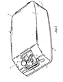
- the fuel tank generally designated by the reference numeral 1 has a structure substantially parallelepipedal in shape, comprising a slightly convex top wall 2, two side walls 3 and 4, a bottom wall 5, a front wall 6 and a rear wall 7.
- the front wall 6 Applied on the front wall 6 is a conventional transport handle 8, which is positioned in this location in order to make the transport by hand of the fuel tank 1 easier.
- the front wall 6 has an inclined portion 9 merging in the top wall 2 and in the inclined portion 9 a recess 10 is provided, the bottom 11 of which extends at an angle of about 45° to the tank bottom wall 5.
- a tank filler 12 provided with the closure cap 13, with the axis of this tank filler being perpendicular to the bottom 11 of recess 10 and also applied to this bottom 11 is a fuel supply pipe 14 provided with the conventional fitting 15 intended to receive the end of a hose the other end of which is to be connected to the outboard motor.
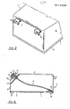
- Fig.2 shows the rear wall 7 of the fuel tank 1, which is provided with a pair of brackets 16 located near the top wall 2 and intended to hook the fuel tank 1 to a fixed portion of the hull in order to prevent dangerous movements of the f-uel tank due to hull movements.
- the brackets 16 are particularly useful to secure the fuel - tank in a suitable remote receptacle, because in this case the tank filler does not project beyond the tank top wall.
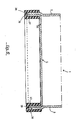
- Fig.3 illustrates the inside of the fuel tank 1 in order to show the arrangement of the suction pipe 17 extending into the fuel tank 1 up to a corner thereof opposite the corner to which the fuel supply pipe 14 is applied and having at the free end a fuel filter 18, which can be secured or not to the tank bottom wall.19 designates feet for supporting the tank on the relevant hull portion.
- Figs.4 and 5 show an embodiment in which the tank filler 12 and the fuel supply pipe 14 are made as an integral assembly generally indicated by the reference numeral 20.
- This assembly is comprised of a substantially square shaped supporting plate 26 having holes 27 intended to secure it to the bottom 11 of the recess 10 provided in the fuel tank 1.
- the supporting plate 25 is provided with the tank filler 12, the fuel supply pipe 14 and a seat 28 for housing a fuel level gauge 29, all these elements being integrally obtained in a single molding operation of a suitable plastic material .
- the supporting plate 26 On its lower surface the supporting plate 26 is provided with the conventional fitting 21 for connection of the suction pipe 17, with the axis of the fitting being aligned with the fuel supply pipe axis.
- Fig.6 shows the embodiment wherein the bottom wall 5 comprises a reverse drawn portion 36 the side walls 37 of which are welded to the tank side walls so as to form a peripheral rim 38 depending from the tank bottom. Forcedly applied on this peripheral rim is a U-shaped strip 39 of elastomeric material, so that this strip 39 is positioned by this forced insertion and covers the peripheral rim 38 on all its extent.
- the fuel tank just described is capable to resist the rolling and pitching movements of the hull since the friction coefficient of the elastomeric strip is choosen in such a manner as to prevent the fuel tank, particularly when it is in a full condition, from sliding on its supporting portion. Therefore, the possibility that the hull of the hull portion receiving the fuel tank is damaged by impacts of the latter against the hull is avoided.
- Another advantage is that the above elastomeric strip can be easily applied on the depending peripheral tank rim for its substitution when it is worn.
Landscapes
- Engineering & Computer Science (AREA)
- Life Sciences & Earth Sciences (AREA)
- Sustainable Development (AREA)
- Sustainable Energy (AREA)
- Chemical & Material Sciences (AREA)
- Combustion & Propulsion (AREA)
- Transportation (AREA)
- Mechanical Engineering (AREA)
- Cooling, Air Intake And Gas Exhaust, And Fuel Tank Arrangements In Propulsion Units (AREA)
- Details Of Rigid Or Semi-Rigid Containers (AREA)
Applications Claiming Priority (6)
| Application Number | Priority Date | Filing Date | Title |
|---|---|---|---|
| IT2058483U | 1983-01-24 | ||
| ITMI1983U20585U IT8320585U1 (it) | 1983-01-24 | 1983-01-24 | Struttura di appoggio di serbatoi di combustibile per motori fuoribordo, di tipo portatile. |
| IT2058683U | 1983-01-24 | ||
| IT2058583U | 1983-01-24 | ||
| ITMI1983U20586U IT8320586U1 (it) | 1983-01-24 | 1983-01-24 | Struttura perfezionata di serbatoi di combustione portatile, per motori fuoribordo |
| ITMI1983U20584U IT8320584U1 (it) | 1983-01-24 | 1983-01-24 | Complesso monoblocco di riempimento e di prelievo del combustibile per serbatoi di combustibile di tipo portatile particolarmente per motori fuoribordo. |
Publications (2)
| Publication Number | Publication Date |
|---|---|
| EP0114585A2 true EP0114585A2 (fr) | 1984-08-01 |
| EP0114585A3 EP0114585A3 (fr) | 1985-01-09 |
Family
ID=27273078
Family Applications (1)
| Application Number | Title | Priority Date | Filing Date |
|---|---|---|---|
| EP83830283A Withdrawn EP0114585A3 (fr) | 1983-01-24 | 1983-12-27 | Réservoir portatif d'essence pour moteurs hors-bords |
Country Status (1)
| Country | Link |
|---|---|
| EP (1) | EP0114585A3 (fr) |
Cited By (3)
| Publication number | Priority date | Publication date | Assignee | Title |
|---|---|---|---|---|
| EP0905373A1 (fr) * | 1997-09-30 | 1999-03-31 | Deere & Company | Dispositif d'alimentation en carburant |
| USD609776S1 (en) | 2009-04-15 | 2010-02-09 | Unified Marine, Inc. | Fuel tank |
| EP4227136A1 (fr) * | 2022-02-08 | 2023-08-16 | Brunswick Corporation | Ensemble réservoir de carburant portable et support de réservoir de carburant portable |
Family Cites Families (4)
| Publication number | Priority date | Publication date | Assignee | Title |
|---|---|---|---|---|
| DE1898319U (de) * | 1964-04-16 | 1964-08-06 | Herbert J Stender | Kanister, insbesondere benzinkanister, zum einlegen in die felge eines kraftfahrzeugrades. |
| FR2332951A1 (fr) * | 1975-11-28 | 1977-06-24 | Ragonot Seb | Systeme d'alimentation en produit liquide stocke dans un reservoir |
| SE398627B (sv) * | 1976-04-28 | 1978-01-09 | Volvo Penta Ab | Anordning vid utombordsmotorer |
| DE2641450A1 (de) * | 1976-09-15 | 1978-03-16 | Klaus Worch | Radfelgen-reservetank |
-
1983
- 1983-12-27 EP EP83830283A patent/EP0114585A3/fr not_active Withdrawn
Cited By (5)
| Publication number | Priority date | Publication date | Assignee | Title |
|---|---|---|---|---|
| EP0905373A1 (fr) * | 1997-09-30 | 1999-03-31 | Deere & Company | Dispositif d'alimentation en carburant |
| USD609776S1 (en) | 2009-04-15 | 2010-02-09 | Unified Marine, Inc. | Fuel tank |
| USD625774S1 (en) | 2009-04-15 | 2010-10-19 | Unified Marine, Inc. | Fuel tank |
| EP4227136A1 (fr) * | 2022-02-08 | 2023-08-16 | Brunswick Corporation | Ensemble réservoir de carburant portable et support de réservoir de carburant portable |
| US12070999B2 (en) | 2022-02-08 | 2024-08-27 | Brunswick Corporation | Portable fuel tank assembly and portable fuel tank support |
Also Published As
| Publication number | Publication date |
|---|---|
| EP0114585A3 (fr) | 1985-01-09 |
Similar Documents
| Publication | Publication Date | Title |
|---|---|---|
| US5114046A (en) | Above ground fuel storage and dispensing apparatus | |
| US6172332B1 (en) | Fuel tank filler assembly for engine driven welder | |
| US5293951A (en) | Battery safety unit and method | |
| US4802514A (en) | Overflow spillage preventer for fuel tanks in boats | |
| AU629782B2 (en) | Housing arrangement for fluid pump and tank | |
| US5590806A (en) | Fuel fill pipe shelf for a generator set fuel tank | |
| EP0114585A2 (fr) | Réservoir portatif d'essence pour moteurs hors-bords | |
| US5667091A (en) | Mounting system for floating roof seals | |
| US4537437A (en) | Nozzle positioner for automatic fuel tank | |
| US4098218A (en) | Outboard motor with removable combination fuel tank and shroud | |
| US3343703A (en) | Tank construction | |
| US5533641A (en) | Locking cover assembly | |
| US5251773A (en) | Fuel tank assembly | |
| US3774803A (en) | Fuel tank air vent line | |
| JPH0534986Y2 (fr) | ||
| US4298130A (en) | Anti-theft motor fuel tank | |
| SU1281170A3 (ru) | Топливный бак транспортного средства | |
| US3334821A (en) | Anti-spill filling hose nozzle | |
| AU758763B2 (en) | Improved fuel filling point | |
| US5246793A (en) | Battery safety unit | |
| US1789492A (en) | Combination gas tank and filling neck lock | |
| US3435846A (en) | Tank fittings | |
| JP7554587B2 (ja) | 箱装置 | |
| WO1986004319A1 (fr) | Tuyau souple de raccordement entre deux recipients | |
| JPH0625438Y2 (ja) | 小型滑走艇の燃料タンク取付構造 |
Legal Events
| Date | Code | Title | Description |
|---|---|---|---|
| PUAI | Public reference made under article 153(3) epc to a published international application that has entered the european phase |
Free format text: ORIGINAL CODE: 0009012 |
|
| AK | Designated contracting states |
Designated state(s): AT BE CH DE FR GB LI LU NL SE |
|
| PUAL | Search report despatched |
Free format text: ORIGINAL CODE: 0009013 |
|
| AK | Designated contracting states |
Designated state(s): AT BE CH DE FR GB LI LU NL SE |
|
| STAA | Information on the status of an ep patent application or granted ep patent |
Free format text: STATUS: THE APPLICATION IS DEEMED TO BE WITHDRAWN |
|
| 18D | Application deemed to be withdrawn |
Effective date: 19850910 |
|
| RIN1 | Information on inventor provided before grant (corrected) |
Inventor name: LUPIERI, GIORGIO |