EP0114676A2 - Dispositif pour la projection de films ou diapositives - Google Patents
Dispositif pour la projection de films ou diapositives Download PDFInfo
- Publication number
- EP0114676A2 EP0114676A2 EP84100560A EP84100560A EP0114676A2 EP 0114676 A2 EP0114676 A2 EP 0114676A2 EP 84100560 A EP84100560 A EP 84100560A EP 84100560 A EP84100560 A EP 84100560A EP 0114676 A2 EP0114676 A2 EP 0114676A2
- Authority
- EP
- European Patent Office
- Prior art keywords
- arrangement according
- projector
- projection
- spars
- projection screen
- Prior art date
- Legal status (The legal status is an assumption and is not a legal conclusion. Google has not performed a legal analysis and makes no representation as to the accuracy of the status listed.)
- Withdrawn
Links
Images


Classifications
-
- G—PHYSICS
- G03—PHOTOGRAPHY; CINEMATOGRAPHY; ANALOGOUS TECHNIQUES USING WAVES OTHER THAN OPTICAL WAVES; ELECTROGRAPHY; HOLOGRAPHY
- G03B—APPARATUS OR ARRANGEMENTS FOR TAKING PHOTOGRAPHS OR FOR PROJECTING OR VIEWING THEM; APPARATUS OR ARRANGEMENTS EMPLOYING ANALOGOUS TECHNIQUES USING WAVES OTHER THAN OPTICAL WAVES; ACCESSORIES THEREFOR
- G03B21/00—Projectors or projection-type viewers; Accessories therefor
- G03B21/54—Accessories
- G03B21/56—Projection screens
- G03B21/58—Projection screens collapsible, e.g. foldable; of variable area
-
- G—PHYSICS
- G03—PHOTOGRAPHY; CINEMATOGRAPHY; ANALOGOUS TECHNIQUES USING WAVES OTHER THAN OPTICAL WAVES; ELECTROGRAPHY; HOLOGRAPHY
- G03B—APPARATUS OR ARRANGEMENTS FOR TAKING PHOTOGRAPHS OR FOR PROJECTING OR VIEWING THEM; APPARATUS OR ARRANGEMENTS EMPLOYING ANALOGOUS TECHNIQUES USING WAVES OTHER THAN OPTICAL WAVES; ACCESSORIES THEREFOR
- G03B21/00—Projectors or projection-type viewers; Accessories therefor
- G03B21/54—Accessories
- G03B21/56—Projection screens
- G03B21/60—Projection screens characterised by the nature of the surface
- G03B21/62—Translucent screens
Definitions
- the invention relates to an arrangement for the projection of films or slides with a projector and a projection screen.
- the invention has for its object to avoid these disadvantages and to provide an easy to set up arrangement for the projection of films or slides. This is achieved in that a collapsible or pluggable linkage is provided on which the projection screen and the projector can be attached. This makes it possible, by means of a set-up procedure, which corresponds to that of a projection screen attached to a tripod, to make films or slides easy to handle, reliable and visually convincing. It is particularly advantageous that the projector is always arranged at a fixed distance in front of the projection screen, so that simple optics that are fixed at this distance are sufficient.
- the linkage has bars for fastening the projection screen, a support part for the projector, and legs.
- the entire arrangement also serves as a tripod.
- the projection screen can be attached to the bars using the bars. No great demands are made on the technical design of the projection screen, for example with regard to the roll-up mechanism.
- the spars for the projection screen are connected to one another and to the support part via struts, and the struts and support part are supported by legs.
- the spars, the struts and the legs for the spars are advantageously connected to one another by means of a connecting piece.
- Each connection can have a hinge joint.
- the hinge joints can advantageously be locked in the position of use. This can be done in such a way that the sliding surfaces of the hinge joints have projections and corresponding recesses which can be brought into engagement with one another in a defined angular position of the hinge, and that these surfaces are elastically pressed against one another.
- the side rails have, at the upper ends against the force of a spring, telescopically displaceable support parts for the upper holding rod, which preferably have a cross section at the upper end V-shaped or U-shaped.
- the projection screen is rolled out and the lower support rod is suspended in corresponding lower brackets, which can also be V-shaped or U-shaped in cross section, and which are attached to the connecting pieces.
- the support part for the projector or the projector itself can be provided with interlocking parts.
- the projector can be fastened in a particularly simple manner in a defined position relative to the projection screen.
- the projector is provided with pins that can be inserted into corresponding holes in the support part.
- the dimensions of the arrangement according to the invention are chosen so that the parts from which it is constructed are still easy to handle and the image generated is also clearly visible to several viewers. This can be done, for example, in the arrangement described above achieve that the projection screen has an edge length of 0.5 to 1.5 m, preferably about 1 m.
- the distance between the projector can be about 1 m to 1.5 m.
- the pillars of the side rails can be about 0.5 m to 1 m long.
- An ideal distance for the viewer can be between 1.5 m and 2 m. Depending on the main application, deviations from the dimensions given above and only given as examples are possible.
- a frame is provided, on one side of which the spars for fastening the projection wall and legs are articulated and on which the support part for the projector is fastened, and on the opposite side of which a reflection mirror and at least one pillar are pivotally attached.
- the projection screen can consist of a matt screen which is observed from the direction in which the projector also stands.
- the reflection mirror can be adjusted, preferably locked, in a defined angular position, which is matched to the end position of the focusing screen in the unfolded state.
- the frame can be formed in one piece for reasons of stability. However, it can also be folded or plugged together here.
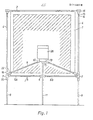
- FIGS. 1 to 8 has a roll-up projection wall 1 which is fastened to an upper holding rod 2 and a lower holding rod 3.
- the upper support rod 2 is supported in a manner to be described in more detail on two side rails 4 which are connected at their lower end by a cross strut 5 which consists of the sections 5A and 5B which are connected to one another via a hinge joint piece 6.
- the side rails 4 and the lower cross strut 5 are fastened in a connecting element 7 to which a supporting leg 8 is also articulated.
- Struts 9 are also fastened to the connecting elements 7 and are connected via hinge joints 10 to a support part 13 for a projector 26.
- a support leg 11 is pivotally articulated with a hinge part 12.
- the two side rails 4 are provided at their upper ends with a support part 14 which can be telescopically displaced in the side rails 4 against the force of a helical spring 15 and which ends in a fork-like holder 16 into which the upper support rod 2 of the projection wall 1 can be suspended.
- the lower support rod 3 is in a fork-like lower holder 17th attachable, which is attached to the connecting element 7.
- FIG. 4 the connecting element 7 between the spar 4, the support leg 8 and the strut 9 is shown enlarged.
- the spar 4 ends in a hinge part 18 which can be pivoted about a bolt 19 on the connecting part 7.
- the foot part 8 is fastened in a corresponding manner in a hinge part 20 which can be pivoted about a bolt 21.
- the connecting part 7 has an extension 7A, on which a hinge part 22, in which the strut 9 is fastened, is pivotably articulated by means of a bolt 23.
- the hinge part 24, to which one part 5A of the cross strut 5 is fastened, is also articulated on the same bolt 23. This ends in the hinge part 6, which is pivotable about a bolt 6A.
- all hinge parts have latching devices which snap into use and, if appropriate, also in the folded position of the arrangement. This ensures that the arrangement is particularly stable in these positions.
- a particularly simple and advantageous latching device is described in more detail below in connection with the connecting element 7 shown in FIGS. 6 to 8.
- the hinge part 20, which can be pivoted about the axis 21 on the connecting piece 7, has a raised rib 20A which is wedge-shaped in cross section on the surface facing the connecting piece 7.
- the connecting part 7 is provided with a corresponding recess 7A with which this rib-like projection can be brought into engagement when the foot part 8 is pivoted out so that it forms an extension of the spar 4.
- a rotation about the axis 21 and a disengagement of the projection 20A from the recess 7A of the connecting part 7 is possible in that the axis 21 a movement of the parts 7 and 20 in the direction of Axis 21 allows, both parts being pressed against each other by a compression spring 25 arranged around the axis 21.
- FIGS. 1 to 3 in the use position can be folded in such a way that first the lower support rod 3 of the projection screen 1 is pulled out of the lower holder 17 in the direction shown by an arrow in FIG. 6 and then onto this support rod 3 is rolled up. Then the upper support rod 2 is pulled out of the fork-like holder 16 at the upper end of the spar 4.
- the legs 8 are folded up about the axes 21 to the bars 4.
- the two sections 5A and 5B of the cross strut 5 are then folded together about the axis 6A of the hinge part 6 until they abut one another.
- the struts 9 pivot about the axes 23 of the hinge parts 22 and the axes 27 of the hinge parts 10 until these hinge parts abut one another and the struts 9 are aligned parallel to one another.
- the legs 8 are pivoted about the pivot axes 21, the leg 11 about the pivot axes 28, and the spars 4 about the pivot axes 19 in the manner indicated by the arrows in FIG. 4 until all parts of the linkage abut one another.
- the arrangement can be stored in a small space and transported in a simple manner.
- the legs 8 and 11 are unfolded in the opposite manner to that described above until the projection 20A snaps into the corresponding recess in the connecting piece 7, as shown in FIG. 8. Then the side members 4 are erected and pulled apart until the sections 5A and 5B of the cross strut 5 are aligned. After that the Upper support rod 2 of the projection screen 1 is placed on the upper, fork-like holders 16 and the projection screen 1 is rolled out. By pulling in the direction of the arrow shown in Fig. 6, the support members 14 are moved downward against the force of the spring 15. As a result, the lower support rod 3 can be suspended in the lower holder 17. After releasing the projection screen 1 is stretched. Then the projector 26 with the pins 26A arranged on its underside is inserted into the bores 13A of the support part 13. The arrangement is then ready for showing films or slides.
- the legs 8 and 11 can remain in the folded position with the spars and struts of the linkage otherwise brought into use.
- the projection screen 1 is square and has a side length of 1000 mm.
- the distance of the lens of the projector 26 from the projection wall 1 is also about 1000 mm.
- the fold-out foot parts 8 with which the side rails 4 are supported are approximately 500 mm long.
- an image of about 900 mm edge length is created at eye level of the seated viewer.
- FIGS. 9 and 10 show a further exemplary embodiment of the arrangement according to the invention. It differs from the exemplary embodiment initially described in that a mirror 40 is provided for deflecting the beam path, and in that the projection wall 1 is not a roll-up screen, but a matt screen 41.
- the linkage of the arrangement according to the invention here has a closed frame 30 which can be formed in one piece or can be plugged together or folded together.
- a supporting leg 31 is articulated on the underside of a connecting part 32.
- a spar 34 is pivotally articulated.
- a further leg 33 is pivotably articulated on a connecting part 35.
- a screen 41 serving as a projection screen is attached to the bars 34 by means of brackets 38.
- the support part 13 for the projector 26 is fastened on the strut 30B of the linkage 30 running parallel to this focusing screen 41 and parallel to this.
- a holding clamp 36 which can be pivoted about this connecting part 30A and on which a strut 37 is fastened.
- Brackets 38 for a mirror 40 are fastened to this strut 37.
- This mirror can either be steplessly adjusted in its angular position or it is provided with a latching device which automatically detects it in the position which results in the correct projection of the image generated by the projector 26 on the unfolded focusing screen 41.
- This embodiment allows an even more compact structure of the arrangement according to the invention than that described initially.
- the images projected by the projector 26 are thereby thrown by the mirror 40 onto the focusing screen 41 and can be viewed by the viewer in the direction of the arrow B from be considered from the side on which the projector 26 is arranged.
- the distance between the lens of the projector 26 and the mirror 40 and thus also the distance between the mirror 40 and the focusing screen 41 is approximately 800 mm in one embodiment.
- the dimensions of the mirror 40 are of the order of 500 x 500 mm, those of the focusing screen 41 are approximately 750 x 750 mm.
- This embodiment can be folded up in a particularly simple manner from the position shown in FIG. 9 and thus transported or stored in a space-saving manner.
- the mirror 40 is first folded into the plane of the frame 30 in the direction indicated by an arrow.
- the spars 34 with the focusing screen 41 are also folded in the direction of the arrow into this plane.
Landscapes
- Physics & Mathematics (AREA)
- General Physics & Mathematics (AREA)
- Overhead Projectors And Projection Screens (AREA)
- Projection Apparatus (AREA)
Applications Claiming Priority (4)
| Application Number | Priority Date | Filing Date | Title |
|---|---|---|---|
| DE3301782 | 1983-01-20 | ||
| DE19833301782 DE3301782A1 (de) | 1983-01-20 | 1983-01-20 | Anordnung zur projektion von filmen oder diapositiven |
| DE3319378 | 1983-05-27 | ||
| DE19833319378 DE3319378A1 (de) | 1983-01-20 | 1983-05-27 | Anordnung zur projektion von filmen oder diapositiven |
Publications (2)
| Publication Number | Publication Date |
|---|---|
| EP0114676A2 true EP0114676A2 (fr) | 1984-08-01 |
| EP0114676A3 EP0114676A3 (fr) | 1984-08-22 |
Family
ID=25807666
Family Applications (1)
| Application Number | Title | Priority Date | Filing Date |
|---|---|---|---|
| EP84100560A Withdrawn EP0114676A3 (fr) | 1983-01-20 | 1984-01-19 | Dispositif pour la projection de films ou diapositives |
Country Status (1)
| Country | Link |
|---|---|
| EP (1) | EP0114676A3 (fr) |
Cited By (5)
| Publication number | Priority date | Publication date | Assignee | Title |
|---|---|---|---|---|
| FR2669749A1 (fr) * | 1990-11-23 | 1992-05-29 | Obuljen | Dispositif pour permettre la visualisation simultanee d'une image a reproduire et de l'image modele proprement dite. |
| GB2366927A (en) * | 2000-09-07 | 2002-03-20 | Guy Spencer Edney | Projection unit |
| EP1785064A1 (fr) * | 2005-11-10 | 2007-05-16 | GfP (Gesellschaft für Produktivitätsplanung und Produktentwicklung)mbH | Dispositif destiné à supporter un panneau de projection |
| AU2005203204B2 (en) * | 2000-09-07 | 2007-06-28 | Guy Spencer Edney | Projection Unit |
| KR101106723B1 (ko) * | 2009-08-12 | 2012-01-18 | 박용현 | 스크린과 프로젝터 일체형 프레임 이동장치 |
Family Cites Families (6)
| Publication number | Priority date | Publication date | Assignee | Title |
|---|---|---|---|---|
| US1662586A (en) * | 1925-11-07 | 1928-03-13 | Newman Hugo | Foldable supporting frame for screens |
| GB672802A (en) * | 1949-08-31 | 1952-05-28 | Lord Mayor Aldermen Cit | An optical rear projection screen unit |
| US2617328A (en) * | 1949-12-21 | 1952-11-11 | Stableford John Leslie | Rear projection screen unit for picture projections |
| GB887916A (en) * | 1958-08-30 | 1962-01-24 | John Michael Denton | Improvements in or relating to projection screens |
| US3144899A (en) * | 1962-02-26 | 1964-08-18 | Stewart La Mar Roy | Portable motion picture screen |
| US3494405A (en) * | 1968-07-15 | 1970-02-10 | Radiant Corp | Screen mounting for projected pictures |
-
1984
- 1984-01-19 EP EP84100560A patent/EP0114676A3/fr not_active Withdrawn
Cited By (7)
| Publication number | Priority date | Publication date | Assignee | Title |
|---|---|---|---|---|
| FR2669749A1 (fr) * | 1990-11-23 | 1992-05-29 | Obuljen | Dispositif pour permettre la visualisation simultanee d'une image a reproduire et de l'image modele proprement dite. |
| GB2366927A (en) * | 2000-09-07 | 2002-03-20 | Guy Spencer Edney | Projection unit |
| GB2366927B (en) * | 2000-09-07 | 2003-03-26 | Guy Spencer Edney | Projection unit |
| US6995906B2 (en) | 2000-09-07 | 2006-02-07 | Guy Spencer Edney | Projection unit |
| AU2005203204B2 (en) * | 2000-09-07 | 2007-06-28 | Guy Spencer Edney | Projection Unit |
| EP1785064A1 (fr) * | 2005-11-10 | 2007-05-16 | GfP (Gesellschaft für Produktivitätsplanung und Produktentwicklung)mbH | Dispositif destiné à supporter un panneau de projection |
| KR101106723B1 (ko) * | 2009-08-12 | 2012-01-18 | 박용현 | 스크린과 프로젝터 일체형 프레임 이동장치 |
Also Published As
| Publication number | Publication date |
|---|---|
| EP0114676A3 (fr) | 1984-08-22 |
Similar Documents
| Publication | Publication Date | Title |
|---|---|---|
| DE19544615A1 (de) | Zusammenlegbarer Laufstall | |
| EP0114676A2 (fr) | Dispositif pour la projection de films ou diapositives | |
| DE19837987A1 (de) | Tisch mit einer Tischplatte | |
| DE2903196C2 (de) | Fahrbarer Krankenstuhl | |
| DE3446579C2 (de) | Zusammenklappbares Untergestell | |
| DE3319378A1 (de) | Anordnung zur projektion von filmen oder diapositiven | |
| DE3311600A1 (de) | Stativ | |
| DE3301782A1 (de) | Anordnung zur projektion von filmen oder diapositiven | |
| DE4120501C1 (en) | Music stand with desk and stand post - has several support elements in desk, with joint permitting unfolding to flat music support face | |
| DE10141555A1 (de) | Tisch | |
| EP0274569A1 (fr) | Bureau avec tablette supplémentaire | |
| DE4230896C1 (de) | Arbeitsprojektor | |
| DE69718110T2 (de) | Kinderbett | |
| DE69702410T2 (de) | Leiterträger für Fahrzeuge | |
| DE4108421C1 (en) | Folding pushchair for children - has crossed support rolls and two-armed levers forming connecting links | |
| DE2717188C2 (de) | Transportable und zusammenklappbare Werkbank | |
| DE2646177C3 (fr) | ||
| DE19951695A1 (de) | Staffelei | |
| DE2530769A1 (de) | Aus zwei haelften bestehende tischtennisplatte | |
| DE9414045U1 (de) | Rahmenanordnung für einen zusammenfaltbaren Laufstall | |
| DE3151631A1 (de) | Transportable projektionsleinwand | |
| DE29923299U1 (de) | Staffelei | |
| DE3418062A1 (de) | Transportable projektionswand | |
| DE102024122864A1 (de) | Faltgestell für ein Pagodenzelt | |
| DE20003897U1 (de) | Ausziehtisch |
Legal Events
| Date | Code | Title | Description |
|---|---|---|---|
| PUAI | Public reference made under article 153(3) epc to a published international application that has entered the european phase |
Free format text: ORIGINAL CODE: 0009012 |
|
| PUAL | Search report despatched |
Free format text: ORIGINAL CODE: 0009013 |
|
| AK | Designated contracting states |
Designated state(s): BE DE FR GB IT NL SE |
|
| AK | Designated contracting states |
Designated state(s): BE DE FR GB IT NL SE |
|
| 17P | Request for examination filed |
Effective date: 19850215 |
|
| 17Q | First examination report despatched |
Effective date: 19860509 |
|
| STAA | Information on the status of an ep patent application or granted ep patent |
Free format text: STATUS: THE APPLICATION IS DEEMED TO BE WITHDRAWN |
|
| 18D | Application deemed to be withdrawn |
Effective date: 19860920 |