EP0114714A2 - Vorrichtung mit einer Kathodenstrahlröhre mit Elektronenkanone mit niedrigem Rauschen - Google Patents
Vorrichtung mit einer Kathodenstrahlröhre mit Elektronenkanone mit niedrigem Rauschen Download PDFInfo
- Publication number
- EP0114714A2 EP0114714A2 EP84200065A EP84200065A EP0114714A2 EP 0114714 A2 EP0114714 A2 EP 0114714A2 EP 84200065 A EP84200065 A EP 84200065A EP 84200065 A EP84200065 A EP 84200065A EP 0114714 A2 EP0114714 A2 EP 0114714A2
- Authority
- EP
- European Patent Office
- Prior art keywords
- cathode
- electrode
- anode
- gun
- electrons
- Prior art date
- Legal status (The legal status is an assumption and is not a legal conclusion. Google has not performed a legal analysis and makes no representation as to the accuracy of the status listed.)
- Granted
Links
- 238000010894 electron beam technology Methods 0.000 claims description 11
- 230000007423 decrease Effects 0.000 claims description 8
- 230000008859 change Effects 0.000 claims description 6
- 230000005684 electric field Effects 0.000 claims description 3
- 238000009826 distribution Methods 0.000 description 14
- 230000000694 effects Effects 0.000 description 5
- 238000010276 construction Methods 0.000 description 4
- 230000004044 response Effects 0.000 description 4
- 230000003247 decreasing effect Effects 0.000 description 3
- 230000003993 interaction Effects 0.000 description 2
- HTUMBQDCCIXGCV-UHFFFAOYSA-N lead oxide Chemical compound [O-2].[Pb+2] HTUMBQDCCIXGCV-UHFFFAOYSA-N 0.000 description 2
- YEXPOXQUZXUXJW-UHFFFAOYSA-N lead(II) oxide Inorganic materials [Pb]=O YEXPOXQUZXUXJW-UHFFFAOYSA-N 0.000 description 2
- XOLBLPGZBRYERU-UHFFFAOYSA-N tin dioxide Chemical compound O=[Sn]=O XOLBLPGZBRYERU-UHFFFAOYSA-N 0.000 description 2
- 230000000007 visual effect Effects 0.000 description 2
- 230000002411 adverse Effects 0.000 description 1
- 230000008878 coupling Effects 0.000 description 1
- 238000010168 coupling process Methods 0.000 description 1
- 238000005859 coupling reaction Methods 0.000 description 1
- 230000001419 dependent effect Effects 0.000 description 1
- 239000011521 glass Substances 0.000 description 1
- 150000002500 ions Chemical class 0.000 description 1
- 239000000463 material Substances 0.000 description 1
- 230000005855 radiation Effects 0.000 description 1
Images

Classifications
-
- H—ELECTRICITY
- H01—ELECTRIC ELEMENTS
- H01J—ELECTRIC DISCHARGE TUBES OR DISCHARGE LAMPS
- H01J29/00—Details of cathode-ray tubes or of electron-beam tubes of the types covered by group H01J31/00
- H01J29/46—Arrangements of electrodes and associated parts for generating or controlling the ray or beam, e.g. electron-optical arrangement
- H01J29/48—Electron guns
- H01J29/484—Eliminating deleterious effects due to thermal effects, electrical or magnetic fields; Preventing unwanted emission
-
- H—ELECTRICITY
- H01—ELECTRIC ELEMENTS
- H01J—ELECTRIC DISCHARGE TUBES OR DISCHARGE LAMPS
- H01J29/00—Details of cathode-ray tubes or of electron-beam tubes of the types covered by group H01J31/00
- H01J29/46—Arrangements of electrodes and associated parts for generating or controlling the ray or beam, e.g. electron-optical arrangement
- H01J29/48—Electron guns
- H01J29/488—Schematic arrangements of the electrodes for beam forming; Place and form of the elecrodes
-
- H—ELECTRICITY
- H01—ELECTRIC ELEMENTS
- H01J—ELECTRIC DISCHARGE TUBES OR DISCHARGE LAMPS
- H01J31/00—Cathode ray tubes; Electron beam tubes
- H01J31/08—Cathode ray tubes; Electron beam tubes having a screen on or from which an image or pattern is formed, picked up, converted, or stored
- H01J31/26—Image pick-up tubes having an input of visible light and electric output
- H01J31/28—Image pick-up tubes having an input of visible light and electric output with electron ray scanning the image screen
- H01J31/34—Image pick-up tubes having an input of visible light and electric output with electron ray scanning the image screen having regulation of screen potential at cathode potential, e.g. orthicon
- H01J31/38—Tubes with photoconductive screen, e.g. vidicon
Definitions
- the invention relates to a low noise electron gun for use in electron tubes such as storage tubes, camera tubes, display tubes and the like.
- the invention is particularly suited for use in beam deflection tubes in which the beam generated by the gun is scanned across a target responsive to electrons by a deflection coil system or the like to either display on or read information stored by the target.
- a tube of this type is described, for example, in an article entitled "An Experimental Light-Weight Colour Television Camera” in Vol. 29, Philips Technical Review No. 11, 1968, pages 325 - 335.
- the electron beam in the camera tube described in the article is generated by a triode gun having a cathode, a control grid which is at a negative potential with respect to the cathode and an anode which is at a positive potential with respect to the cathode.
- the control grid and anode form a lens which focusses the electrons emitted from the cathode to a spot or "cross-over" in the region of the anode.
- the cross-over is then imaged on a photoconductive target by an electron lens and scanned across the target by a deflection coil system.
- the velocity distribution is dependent on the temperature of the cathode and theoretically the best that can be obtained is a Maxwellian distribution corresponding to the actual cathode temperature. In practice, however, the velocity spread of the electrons is greater than that which would correspond to the Maxwellian distribution for the actual cathode temperature.
- One reason for the increased velocity spread is the interaction between electrons in the beam, particularly at the beam crossover, since electrons moving along intersecting tracks will repel each other causing one to move faster and the other one to slow down.
- x-ray radiation emitted by electrons impinging on the anode and positive ions striking the cathode may also release fast electrons which increase the velocity or energy spread of the electron beam.
- the beam velocity distribution imposes a lower limit on the diameter of the spot to which the scanned beam can be focussed on the target and hence the resolution of the camera tube.
- the response rate that is the speed with which the tube reacts to variations in the intensity of the incident light, is also affected by the electron velocity distribution.
- all elements of the target should be stabilized at the same potential after scanning.
- the electrons with excessively high energies will cause the target to be charged to a lower potential than that desired increasing the beam-discharge lag and adversely affecting the response rate of the tube.
- U.S. Patents Nos. 3,894,261 and 3,226,595 disclose electron guns of this type comprising a cathode and an anode which is operated at low positive potential with respect to the cathode.
- U.S. Patent No. 3,831,058 discloses another gun of this type having a cathode, an apertured control grid which is operated at a negative voltage relative to the cathode and an apertured anode which is preferably 50 volts, and at most 125 volts, positive relative to the cathode.
- the lens formed by the electrodes has a very large focal distance relative to the dimensions of the electron gun so that there is no crossover of the beam in the region between the cathode and the anode.
- return beam refers to that portion of the primary electron beam incident on the target which returns from the target back toward the electron gun end of the tube.
- the return beam is comprised primarily of electrons reflected from the target and the electrons inthe primary beam which are not accepted by the target, because, particularly at low incident light intensities, portions of the scanned target are at nearly the same or even slightly negative potential with respect to the cathode.
- the electrons in the return beam travel back toward the gun end of the tube, they are focussed by the magnetic lens onto the anode of the electron gun and scanned across it by the deflection coil system resulting in an emission of secondary electrons.
- the secondary electrons and the electrons in the return beam which are reflected from the anode have energies'corresponding to the anode potential, which in an electron gun without a cross- over is close to the cathode potential. Since the energy levels of these electrons are comparable to the energy of the electrons in the primary beam, the secondary .ad reflected electrons will once again be focussed on and scanned across the target producing an interference signal which appears as a "dark spot" in the visual image.
- the beam current may be varied by varying the potential applied to the first anode. In addition to producing a corresponding change in the cathode current, this also produces a change in the lens field in the region between the anodes. The change in the lens field moves the crossover closer to or further away from the aperture in the second anode. This movement of the crossover results in an increase or decrease respectively, of the beam current, since a larger portion of the beam passes through the aperture when the crossover' moves closer to the second anode and a smaller portion of the beam passes through the aperture when the cross-over moves away from the second anode.
- the change in the beam current due to the movement of the crossover is at least as large, or larger than that produced by the variation in the cathode current due to the increase or decrease of the first anode voltage. Accordingly, this arrangement permits the dynamic beam current control to be effected with a control signal of relatively small amplitude variation. Moreover, large increases in the beam current can be obtained without undue loading of the cathode.
- the electron gun of the invention is particularly suited for use in a camera tube, for example, of the vidicon type.
- the electron gun is mounted at one end of the tube envelope with the cathode and the anodes spaced along and centered about the tube axis, the requisite voltages being supplied to the gun via connecting pins extending through the envelope.
- the opposite end of the envelope is provided with a window panel and a photosensitive target arranged near or on the inner surface of the window with a transparent signal plate disposed therebetween.
- the camera tube further includes an electron lens whose parameters are chosen so that the aperture in the second anode is imaged onto the target to produce an electron spot which is scanned across the target by a deflection coil system mounted about the tube envelope.
- the electron gun according to the invention substantially eliminates the effect of the return beam in the camera tube.
- the second electrode is at a relatively high positive potential of approximately +300 volts with respect to the cathode.
- the energy of the released secondary electrons will have a sufficiently different energy distribution from that of the electrons in the primary beam so that they will not be focused to a spot onto the target by the focusing coil as they travel through the focusing field back to the target.
- this construction substantially eliminates the dark spot in the visual image resulting from the return beam effect in tubes with prior art electron guns of the type described above.
- the camera tube shown in Figure 1 is of the vidicon type and comprises a glass envelope 1 having a window panel 2 secured to one end thereof.
- a photosensitive target 3 Arranged near the inner surface of the window panel 2 is a photosensitive target 3 with a conductive, transparent signal plate 4 positioned between the target 3 and the window panel 2.
- the target 3 may be made of a photoconductive material such as specially actLvated lead monoxide, PbO, and the conductive signal plate 4 may, for example, be a layer of tin dioxide applied to the surface of the target 3.
- the electron gun is mounted in the end of the tube envelope opposite the target end.
- the gun 6 includes a cathode 10, a first anode 11 with an aperture 21 opposite the cathode, and a second anode 12 provided with a central aperture 13.
- the cathode 10 and the two anodes 11 and 12 are spaced along and centered about the tube axis 5 so that the apertures 21 and 31 are concentric with the tube axis 5.
- the requisite voltages are supplied to the various electrodes of electron gun 6 by leads.7' connected to pins 7 which extend through the envelope 1.
- the camera tube shown in Figure 1 further comprises a drift tube 14 enclosing a field free space through which the beam generated by the electron gun 6 travels on its way to the target 3.
- the electron beam is focussed on the target 3 by focussing coils 15 disposed about this region of the tube envelope 1.
- the first anode 11 is connected to a variable voltage source 24 and is operated at a slight positive potential of 5 to 30 volts with respect to the cathode 10.
- the cathode 10 and the first anode 11 form a source of electrons, with the cathode current being determined by the first anode potential.
- the first anode 11 is at approximately +10 volts with respect to the cathode.
- the spacing between anodes 11 and 12 of the electron gun, and the potential difference between these anodes is chosen such that a lens field is produced in the region between the two anodes.
- the lens field converges the electrons emitted from the cathode 10 to a crossover 22 along the tube axis 5 in the region 23 between the two anodes.
- the second anode 12 is connected to a voltage source 25 and is typically operated at a potential between +100 volts and +400 volts and, typically, approximately +300 volts with respect to the cathode.
- the aperture 21 in the first anode 11 is sufficiently small so that the lens field in region 23 does not affect the cathode emission.
- the aperture 13 in the second anode 12 is approximately four times smaller than the aperture 21 in the first anode and its diameter is chosen such that the cross-section of the beam is limited to a diameter which the beam focussing coil 15 is designed to accommodate.
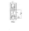
- Figure 4 shows another possible embodiment of the ' invention in which a separate beam-limiting element 30 is used.
- Beam-limiting element 30 has a beam-limiting aperture 32 whose diameter is chosen small enough to limit the cross-section of the electron beam.
- aperture 13 in second anode 12 has an increased diameter so as to pass substantially the entire electron beam therethrough.
- the beam-limiting element 30 is located in a constant-electric-field region of the tube (within drift tube 14). Element 30 may be electrically connected to the drift tube 14 or to another source of the same potential.
- the beam current can be reduced by decreasing the first anode voltage so that the crossover 22 moves further away from anode 12 (or beam-limiting element 30) decreasing the number of electrons passing through the aperture 13 (or aperture .32).
- the beam current can be controlled by signals with a relatively small amplitude variation and minimal changes in the load on the cathode.
- the distance along the tube axis between the cathode 10 and the first anode 11 is 0.3 millimeters and the distance between the first and second anodes is 0.7 millimeters.
- the diameter of the aperture 21 in the first anode 11 is 0.2 millimeters and the diameter of the aperture 13 in the second anode is 0.05 millimeters.
- the first and second anodes are operated at +10 volts and +300 volts, respectively, relative to the cathode.
- the preferred embodiment does not use a separate beam-limiting element ; aperture 13 in second anode 12 performs this function.
- the acceptance curve of the tube with an electron gun of the above-described Figure 2 construction is shown in Figure 3.
- the acceptance curve is a plot of the current accepted by the target as a function of the potential difference between the target and the cathode.
- the accepted current is plotted to a logarithmic scale on the vertical axis and the potential difference is plotted to a linear scale on the horizontal axis.
- the acceptacne curve is related to the velocity spread of the electron beam.
- the velocity distribution in turn, can be expressed as the "temperature" of the beam since a given velocity spread can be regarded as being due to a cathode temperature whose Maxwellian distribution best corresponds to that velocity spread.
- the difference between their respective beam temperatures gives an indication of the velocity distribution or noise in the respective electron beams.
- the beam temperature of a given tube can be derived from its acceptance curve.
- the entire beam current is accepted since substantially all of the electrons in the beam are able to reach the target.
- the accepted current decreases since only a correspondingly decreasing number of the more energetic or fast electrons in the beam are able to reach the target.
- the decrease of the accepted current is exponential and in the log I versus V plot of Figure 3 is represented by the central linear region of the curve.
- the exponential region of the acceptance curve thus resembles the Maxwellian law distribution, which is also exponential, and the beam temperature can therefore be derived from the slope of the exponential region, i.e. the linear portion of the log I versus V acceptance curve.
- the difference between the beam temperatures of two tubes corresponds to the difference between their velocity distributions and, hence, gives an indication of their performance.
- Figure 3 shows an acceptance curve and the derived beam temperature for the electron gun of the invention. From the figure it can be seen that the electron gun of the invention has a beam temperature of 1314°K. This value is significantly lower than that attainable in tubes with conventional triode guns which typically have a beam temperature between 1900°K and 23500K under comparable operating conditions. Moreover, despite the fact that in the gun of the invention the electrons emitted from the cathode are converged to a crossover, the beam temperature is only slightly higher than the 1200 0 K beam temperature typically attained in tubes with known guns without a crossover.
- a camera tube with an electron gun of the invention produces a beam with a temperature between 1300°K and 1500 0 K and will thus give a response rate comparable to known guns without beam crossover.
- Such a tube has the added significant advantages that it eliminates the effects of the return beam and, moreover, permits the beam current to be dynamically controlled with a considerably lower cathode load and a smaller control signal than would be necessary in guns of known construction.
- the electron gun of the invention has been described with reference to a camera tube it should be understood that it may be used with a number of other electron tubes such as pyroelectric vidicons, display tubes and the like.
Landscapes
- Electron Sources, Ion Sources (AREA)
Applications Claiming Priority (2)
| Application Number | Priority Date | Filing Date | Title |
|---|---|---|---|
| US06/460,416 US4549113A (en) | 1981-02-06 | 1983-01-24 | Low noise electron gun |
| US460416 | 1990-01-03 |
Publications (3)
| Publication Number | Publication Date |
|---|---|
| EP0114714A2 true EP0114714A2 (de) | 1984-08-01 |
| EP0114714A3 EP0114714A3 (en) | 1984-08-22 |
| EP0114714B1 EP0114714B1 (de) | 1987-08-05 |
Family
ID=23828616
Family Applications (1)
| Application Number | Title | Priority Date | Filing Date |
|---|---|---|---|
| EP84200065A Expired EP0114714B1 (de) | 1983-01-24 | 1984-01-20 | Vorrichtung mit einer Kathodenstrahlröhre mit Elektronenkanone mit niedrigem Rauschen |
Country Status (5)
| Country | Link |
|---|---|
| US (1) | US4549113A (de) |
| EP (1) | EP0114714B1 (de) |
| JP (1) | JPS59141153A (de) |
| CA (1) | CA1212983A (de) |
| DE (1) | DE3465220D1 (de) |
Cited By (1)
| Publication number | Priority date | Publication date | Assignee | Title |
|---|---|---|---|---|
| EP0570540A4 (en) * | 1991-12-09 | 1994-06-08 | Chen Hsing Yao | Electron gun with low voltage limiting aperture main lens |
Families Citing this family (9)
| Publication number | Priority date | Publication date | Assignee | Title |
|---|---|---|---|---|
| JPS6129045A (ja) * | 1984-07-18 | 1986-02-08 | Hitachi Ltd | 撮像管装置 |
| JPH0719541B2 (ja) * | 1985-04-30 | 1995-03-06 | 株式会社日立製作所 | インライン型カラー受像管 |
| NL8700834A (nl) * | 1987-04-09 | 1988-11-01 | Philips Nv | Diodekanon met samengestelde anode. |
| US5321336A (en) * | 1991-11-26 | 1994-06-14 | Proel Technologie S.P.A. | Electron gun device for controlling the potential of a body in space |
| US5159240A (en) * | 1991-12-09 | 1992-10-27 | Chunghwa Picture Tubes, Ltd. | Low voltage limiting aperture electron gun |
| US5220239A (en) * | 1991-12-09 | 1993-06-15 | Chunghwa Picture Tubes, Ltd. | High density electron beam generated by low voltage limiting aperture gun |
| US5182492A (en) * | 1992-05-20 | 1993-01-26 | Chunghwa Picture Tubes, Ltd. | Electron beam shaping aperture in low voltage, field-free region of electron gun |
| WO2003019603A1 (en) * | 2001-08-28 | 2003-03-06 | Koninklijke Philips Electronics N.V. | Pre-focus lens in a he-crt |
| KR20040041692A (ko) * | 2001-10-12 | 2004-05-17 | 코닌클리케 필립스 일렉트로닉스 엔.브이. | 음극선관 |
Family Cites Families (13)
| Publication number | Priority date | Publication date | Assignee | Title |
|---|---|---|---|---|
| GB542497A (en) * | 1940-05-02 | 1942-01-12 | James Dwyer Mcgee | Improvements in or relating to electron discharge devices |
| US3040205A (en) * | 1960-05-31 | 1962-06-19 | Harold R Walker | Electrostatic vidicon |
| NL160428C (nl) * | 1968-02-13 | 1979-10-15 | Philips Nv | Beeldopneeminrichting met een beeldopneembuis en beeldop- neembuis voor een dergelijke inrichting. |
| JPS5040509B1 (de) * | 1970-01-30 | 1975-12-24 | ||
| NL7107038A (de) * | 1971-05-22 | 1972-11-24 | ||
| US3928784A (en) * | 1971-07-02 | 1975-12-23 | Philips Corp | Television camera tube with control diaphragm |
| US3894261A (en) * | 1973-07-09 | 1975-07-08 | Hughes Aircraft Co | No-crossover electron gun |
| US3924153A (en) * | 1974-03-11 | 1975-12-02 | Westinghouse Electric Corp | Electron gun |
| US4169239A (en) * | 1974-07-26 | 1979-09-25 | Hitachi, Ltd. | Electrostatically focusing type image pickup tubes and method of manufacturing the same |
| JPS5343768A (en) * | 1976-09-30 | 1978-04-20 | Lundbergs Fab Ab N | Apparatus for manufacturing reinforced pipe |
| JPS5471551A (en) * | 1977-11-17 | 1979-06-08 | Matsushita Electric Ind Co Ltd | Electron gun |
| JPS54129871A (en) * | 1978-02-13 | 1979-10-08 | Philips Nv | Device having camera tube |
| JPS5774948A (en) * | 1980-10-29 | 1982-05-11 | Nippon Hoso Kyokai <Nhk> | Electron gun |
-
1983
- 1983-01-24 US US06/460,416 patent/US4549113A/en not_active Expired - Lifetime
-
1984
- 1984-01-19 CA CA000445670A patent/CA1212983A/en not_active Expired
- 1984-01-20 DE DE8484200065T patent/DE3465220D1/de not_active Expired
- 1984-01-20 EP EP84200065A patent/EP0114714B1/de not_active Expired
- 1984-01-23 JP JP59008677A patent/JPS59141153A/ja active Pending
Cited By (1)
| Publication number | Priority date | Publication date | Assignee | Title |
|---|---|---|---|---|
| EP0570540A4 (en) * | 1991-12-09 | 1994-06-08 | Chen Hsing Yao | Electron gun with low voltage limiting aperture main lens |
Also Published As
| Publication number | Publication date |
|---|---|
| JPS59141153A (ja) | 1984-08-13 |
| US4549113A (en) | 1985-10-22 |
| CA1212983A (en) | 1986-10-21 |
| EP0114714A3 (en) | 1984-08-22 |
| EP0114714B1 (de) | 1987-08-05 |
| DE3465220D1 (en) | 1987-09-10 |
Similar Documents
| Publication | Publication Date | Title |
|---|---|---|
| EP0114714B1 (de) | Vorrichtung mit einer Kathodenstrahlröhre mit Elektronenkanone mit niedrigem Rauschen | |
| US4388556A (en) | Low noise electron gun | |
| US2288402A (en) | Television transmitting tube | |
| US2540621A (en) | Electron gun structure | |
| CA1135774A (en) | Cathode-ray tube with low anode potential preventing positive ion formation | |
| US2555091A (en) | Cathode-ray tube | |
| US2322807A (en) | Electron discharge device and system | |
| US2579351A (en) | Isocon pickup tube | |
| US4467243A (en) | Electron gun | |
| US3924153A (en) | Electron gun | |
| US2863087A (en) | Photo-conductive electron discharge tube | |
| US3001098A (en) | X-ray image intensifying device | |
| US3990038A (en) | Electron beam source of narrow energy distribution | |
| US3441786A (en) | Camera tube having a variable resolving aperture | |
| US2887594A (en) | Electron discharge device | |
| US3883773A (en) | Device comprising a television camera tube | |
| US4752715A (en) | Television camera tube | |
| US2840755A (en) | Large storage low noise image tube | |
| US2540637A (en) | Pickup tube system | |
| US3307061A (en) | Electrostatic return beam camera tube | |
| US2914696A (en) | Electron beam device | |
| CA1118831A (en) | Device comprising a television camera tube and television camera for such a device | |
| US2227092A (en) | Cathode ray tube | |
| EP0169480B1 (de) | Fernsehbildaufnahmeröhre | |
| US3175114A (en) | Storage cathode ray tubes |
Legal Events
| Date | Code | Title | Description |
|---|---|---|---|
| PUAI | Public reference made under article 153(3) epc to a published international application that has entered the european phase |
Free format text: ORIGINAL CODE: 0009012 |
|
| PUAL | Search report despatched |
Free format text: ORIGINAL CODE: 0009013 |
|
| AK | Designated contracting states |
Designated state(s): DE FR GB |
|
| AK | Designated contracting states |
Designated state(s): DE FR GB |
|
| 17P | Request for examination filed |
Effective date: 19841122 |
|
| 17Q | First examination report despatched |
Effective date: 19860226 |
|
| GRAA | (expected) grant |
Free format text: ORIGINAL CODE: 0009210 |
|
| AK | Designated contracting states |
Kind code of ref document: B1 Designated state(s): DE FR GB |
|
| REF | Corresponds to: |
Ref document number: 3465220 Country of ref document: DE Date of ref document: 19870910 |
|
| ET | Fr: translation filed | ||
| PLBE | No opposition filed within time limit |
Free format text: ORIGINAL CODE: 0009261 |
|
| STAA | Information on the status of an ep patent application or granted ep patent |
Free format text: STATUS: NO OPPOSITION FILED WITHIN TIME LIMIT |
|
| 26N | No opposition filed | ||
| REG | Reference to a national code |
Ref country code: FR Ref legal event code: CD |
|
| PGFP | Annual fee paid to national office [announced via postgrant information from national office to epo] |
Ref country code: GB Payment date: 19951222 Year of fee payment: 13 |
|
| PGFP | Annual fee paid to national office [announced via postgrant information from national office to epo] |
Ref country code: FR Payment date: 19960130 Year of fee payment: 13 |
|
| PGFP | Annual fee paid to national office [announced via postgrant information from national office to epo] |
Ref country code: DE Payment date: 19960322 Year of fee payment: 13 |
|
| PG25 | Lapsed in a contracting state [announced via postgrant information from national office to epo] |
Ref country code: GB Effective date: 19970120 |
|
| GBPC | Gb: european patent ceased through non-payment of renewal fee |
Effective date: 19970120 |
|
| PG25 | Lapsed in a contracting state [announced via postgrant information from national office to epo] |
Ref country code: FR Effective date: 19970930 |
|
| PG25 | Lapsed in a contracting state [announced via postgrant information from national office to epo] |
Ref country code: DE Effective date: 19971001 |
|
| REG | Reference to a national code |
Ref country code: FR Ref legal event code: ST |