EP0114914A1 - Dispositif pour détecter et évaluer des bandes de mesure colorimétriques sur une feuille d'impression - Google Patents
Dispositif pour détecter et évaluer des bandes de mesure colorimétriques sur une feuille d'impression Download PDFInfo
- Publication number
- EP0114914A1 EP0114914A1 EP83100841A EP83100841A EP0114914A1 EP 0114914 A1 EP0114914 A1 EP 0114914A1 EP 83100841 A EP83100841 A EP 83100841A EP 83100841 A EP83100841 A EP 83100841A EP 0114914 A1 EP0114914 A1 EP 0114914A1
- Authority
- EP
- European Patent Office
- Prior art keywords
- sheet
- printed sheet
- densitometer
- values
- coordinate
- Prior art date
- Legal status (The legal status is an assumption and is not a legal conclusion. Google has not performed a legal analysis and makes no representation as to the accuracy of the status listed.)
- Granted
Links
Images


Classifications
-
- B—PERFORMING OPERATIONS; TRANSPORTING
- B41—PRINTING; LINING MACHINES; TYPEWRITERS; STAMPS
- B41F—PRINTING MACHINES OR PRESSES
- B41F33/00—Indicating, counting, warning, control or safety devices
- B41F33/0036—Devices for scanning or checking the printed matter for quality control
Definitions
- the invention relates to a device for determining and evaluating color measurement fields on a printed sheet, which lies on a coordinate measuring table, with a densitometer.
- the guides of the densitometer In order to simplify the recurring evaluation of color measurement fields on a printed sheet by means of a densitometer, the guides of the densitometer must be held on rails so that they can move in the x-y direction. In the case of constant repetition of individual measurement processes with the same printed sheets, positioning the densitometer by hand is ruled out because of the inaccuracy that occurs.
- the problem is particularly difficult with different types of paper, such as thin printing paper and thick cardboard.
- the orders in cardboard force the maximum use of the areas to be printed in such a way that there is no space or limited space for color measuring fields on the printed sheet at the most different positions of the printed sheet. This means that the color measurement fields are always at different locations for the different print jobs ; depending on where there is free space for a color measuring field between the print images.
- the invention has for its object to make all areas of the sheet detectable for measurement purposes, whereby when recognizing the position of the sheet on the coordinate measuring table on lighting and not exactly flat resting of the sheet on the coordinate measuring table problems are avoided.
- the position of the color measurement fields on the printed sheet can be detected by means of a device and stored in a first memory, that the position of the printed sheet on the coordinate measuring table can be determined by means of optical scanning elements and It can be stored in a second memory that the values determined by the optical scanning elements can be used to convert the coordinate values from a fixed reference point on the printed sheet to a fixed reference point on the coordinate measuring table and that the densitometer, which can be moved in two directions, can be repeated on the color measuring fields by means of the stored values the printing sheet is movable.
- the position data or the coordinates of the color measurement fields of the printed sheet are entered directly by hand using a keyboard on the coordinate measurement table.
- the printing sheet lies on the coordinate measuring table and the densitometer is brought into position above a color measuring field by means of a target device, and the coordinates of the color measuring fields of the printing sheet are stored by pressing a button on an operating console.
- the third embodiment provides for the data coordinates of the color measurement fields of each individual print order to be imported on a tape.
- the present device enables the color measurement fields to be distributed over the printed sheet in accordance with the respective conditions.
- the color measuring fields can be arranged in a particularly advantageous manner distributed over the entire printed sheet. With the coordinate measuring table and the storage spaces and their ver work, it is then possible to automatically approach and measure these measuring points via the arc.
- a photoelectric matrix for example an image sensor at one corner, is sufficient to determine the exact position of the printed sheet on the coordinate measuring table.
- the accuracy increases if e.g. Three row arrays, two of which are arranged on the base side and one on a transverse side, are conveniently positioned on the coordinate measuring table.
- the arrays are read out sequentially.
- the size of the measured values is proportional to the incident light and the integration time.
- the values read from the arrays are digitized and stored in a downstream memory, which is operated by a control circuit (microprocessor).
- the measured values output by the arrays are stored in a first memory in the state not covered by the sheet, and the measured values of the arrays covered by an sheet are stored in a second memory.
- the minima and maxima are found, by means of which the position of the arc is defined at a reference point.
- the course of these difference values, in particular the turning point in the course of the curve determined by differentiating, can be defined as an arc edge.
- the position of the sheets on the coordinate measuring table can be measured densitometrically, without the printed sheets having to rest against, or be aligned with, fixed stops of the table.
- the densitometer travels over a printed sheet edge, which for this purpose lies in a particularly advantageous manner on a base which forms a contrast to the printed sheet edge. and thereby determines the position of the printed sheet on the coordinate measuring table.
- the calculated values of the above measurement process can serve as correction factors for the measurement coordinates defined for the first time, with which each printed sheet lying in any position on the coordinate measuring table can be measured.
- edges of the sheets to be measured are not flat, but are slightly kinked or curled, and it is also possible to determine the position coordinates on the coordinate measuring table, since a drop shadow of the sheet edge on the photoelectric matrix or the image sensors from the above reasons mentioned is not necessary. Even obliquely incident diffuse light leads to a precise measurement value for the position determination due to the two differentiations.
- Image sensors 2, 3 are provided on the sheet base 1 at a defined distance (A, B) from a reference point (C). Each of these image sensors 2, 3 has a defined number of measuring points arranged in a row, which, when the light falls on them, emit an electrical signal which corresponds in size to the incident quantity of light. Each of these image sensors 2, 3 is assigned two memories 4, 5, the storage capacity of which corresponds to the number of measuring points of the image sensors. A computer 6 checks the memories 4, 5 and, in accordance with the contents of the memory, outputs a value to a further computer 7, which processes all the values of the computer 6 and carries out a position calculation.
- the difference in the memory contents is now processed by the computers 6 and fed to a further computer 7, which calculates the actual position of the sheet.
- the difference between the target and actual position then serves as a correction value for determining the coordinate values for controlling a densitometer or for an optical display.
- FIG. 1 shows a sheet base with image sensors 2, 3 attached to it, which are arranged in a line at a distance B from a fixed reference point C.
- the measuring process for measuring a printed sheet 8 on the sheet base 1 becomes more precise if an additional image sensor 2.2 is arranged on a side edge.
- a significant simplification of the entire measuring process is possible if instead of the image sensors 2, 3, 2.1 only a matrix sensor 2.1 is used which contains 500x500 recording elements.
- the matrix sensor 2.1 can be arranged at each of the four corners of the printed sheet 8. Color measuring fields 14 to 14.3 are randomly distributed on the printed sheet 8.
- the image sensors 2, 3 pass on their measured values to memories 4, 5 or 4.1, 5.1 lying parallel to one another.
- the first values of the image sensor 2 are stored by the uncovered arrays on a storage area 4, and the second values, of the arrays of the image sensor 2 covered by a printed sheet, are stored on a second storage area 5.
- the maxima and minima are found which define the position of the printed sheet 8 at the reference point C.
- the comparison values from the computer 6 and 6.1 become in the computer 7 summarized.
- the printing sheets 8 can thus be detected densitometrically in the xy direction without the printing sheets 8 having to be aligned with their edges at fixed stops.
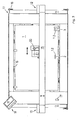
- Fig. 3 shows the technical design of a coordinate measuring table 1.1.
- two image sensors 2, 3 are provided in recesses 1.2 of the sheet base 1.
- On each individual guide rail 11 there are bearings 12, 13 for a cross member 15, which is thus held in a mobile manner.
- the direction of movement of the cross member 15 is possible parallel to the guide rails 11 over the entire coordinate measuring table 1.1.
- End stops 16 prevent the cross member 15 from sliding over the ends of the guide rails 11.
- a densitometer 8.1 and a target device 9 can be moved along the crossmember 15 in the longitudinal direction of the coordinate table 1.1.
- the densitometer 8.1 and the target device 9 can be brought over any color measurement field 14 to 14.3 and measured or positioned.
- the target device 9 contains an optical system, by means of which the exact position above a sighted color measurement field 14 to 14.3 is made visible on a screen with cross hair 20, whereupon the exact coordinates of the target device 9 and thus the color measurement fields 14 to 14.3 can be read and saved. The reading process is triggered manually by pressing a button. Alternatively, it is possible via the keyboard 10 of an operating console 18 to enter individual coordinates in numbers.
- the movements of the densitometer 8.1 are divided into x and y directions on the coordinate measuring table 1.1, which can be carried out by means of stepper motors.
- a stepper motor is arranged on the bearings 12, 13 on the narrow sides of the coordinate measuring table 1.1.
- the second direction of movement of the densitometer 8.1 and the target device 9 is carried out by a further stepping motor along the cross member 15.
- the stepper motors are controlled automatically via the coordinate data when a print sheet 8 is placed on demand.
- a contrast surface 19 for the densitometer 8.1 has been included as a surround of the sheet support 1. proven to be particularly advantageous.
- the densitometer 8.1 is calibrated by means of a measuring element 17.
- the measuring element 17 is located outside the sheet support 1 on the coordinate measuring table 1.1.
Landscapes
- Engineering & Computer Science (AREA)
- Quality & Reliability (AREA)
- Inking, Control Or Cleaning Of Printing Machines (AREA)
- Length Measuring Devices By Optical Means (AREA)
- Length Measuring Devices With Unspecified Measuring Means (AREA)
- Investigating Or Analysing Materials By Optical Means (AREA)
- Spectrometry And Color Measurement (AREA)
Priority Applications (4)
| Application Number | Priority Date | Filing Date | Title |
|---|---|---|---|
| EP83100841A EP0114914B1 (fr) | 1983-01-29 | 1983-01-29 | Dispositif pour détecter et évaluer des bandes de mesure colorimétriques sur une feuille d'impression |
| AT83100841T ATE26674T1 (de) | 1983-01-29 | 1983-01-29 | Vorrichtung zum ermitteln und auswerten von farbmessfeldern auf einem druckbogen. |
| JP58211099A JPS59155710A (ja) | 1983-01-29 | 1983-11-11 | 印刷枚葉紙のインキ測定フイ−ルドを検出しかつ評価するための装置 |
| US06/574,875 US4648048A (en) | 1983-01-29 | 1984-01-30 | Apparatus for determining and evaluating color measurement strips on a printed sheet |
Applications Claiming Priority (1)
| Application Number | Priority Date | Filing Date | Title |
|---|---|---|---|
| EP83100841A EP0114914B1 (fr) | 1983-01-29 | 1983-01-29 | Dispositif pour détecter et évaluer des bandes de mesure colorimétriques sur une feuille d'impression |
Publications (2)
| Publication Number | Publication Date |
|---|---|
| EP0114914A1 true EP0114914A1 (fr) | 1984-08-08 |
| EP0114914B1 EP0114914B1 (fr) | 1987-04-22 |
Family
ID=8190271
Family Applications (1)
| Application Number | Title | Priority Date | Filing Date |
|---|---|---|---|
| EP83100841A Expired EP0114914B1 (fr) | 1983-01-29 | 1983-01-29 | Dispositif pour détecter et évaluer des bandes de mesure colorimétriques sur une feuille d'impression |
Country Status (4)
| Country | Link |
|---|---|
| US (1) | US4648048A (fr) |
| EP (1) | EP0114914B1 (fr) |
| JP (1) | JPS59155710A (fr) |
| AT (1) | ATE26674T1 (fr) |
Cited By (5)
| Publication number | Priority date | Publication date | Assignee | Title |
|---|---|---|---|---|
| DE3631204A1 (de) * | 1986-09-13 | 1988-03-24 | Roland Man Druckmasch | Vorrichtung an druckmaschinen zur densitometrischen erfassung eines messfeldstreifens |
| DE3738850A1 (de) * | 1987-11-16 | 1989-05-24 | Roland Man Druckmasch | Verfahren zur automatischen positionsfindung von druckkontrollstreifen fuer automatisch messende farbdichtemessanlagen |
| DE4100170A1 (de) * | 1991-01-05 | 1992-07-09 | Roland Man Druckmasch | Farbabstimmpult zur visuellen und messtechnischen qualitaetskontrolle von druckbogen |
| WO2002057081A1 (fr) * | 2001-01-18 | 2002-07-25 | Harland Simon Plc | Systeme de commande pour presse d'impression a bobines |
| DE102009021375A1 (de) * | 2009-05-14 | 2010-11-18 | Marc Leppla | Sensor zum Messen einer Lichtgröße und Verfahren zum Kalibrieren eines Monitors |
Families Citing this family (20)
| Publication number | Priority date | Publication date | Assignee | Title |
|---|---|---|---|---|
| DD253679A1 (de) * | 1986-11-13 | 1988-01-27 | Polygraph Leipzig | Verfahren zum regeln der farbdichte |
| SE455539B (sv) * | 1986-05-23 | 1988-07-18 | Electrolux Ab | Elektrooptiskt positionskennande system for ett i plan rorligt foremal, foretredesvis en mobil robot |
| JPS63225115A (ja) * | 1987-03-13 | 1988-09-20 | Ckd Corp | 検査、組付等のための作業対象領域計測設定方法 |
| JPS646547U (fr) * | 1987-07-02 | 1989-01-13 | ||
| DE3812099C2 (de) * | 1988-04-12 | 1995-01-26 | Heidelberger Druckmasch Ag | Verfahren zur Farbsteuerung einer Offsetdruckmaschine |
| JPH0288907A (ja) * | 1988-09-27 | 1990-03-29 | Pfu Ltd | プリンタの印刷精度測定方法及び装置 |
| DE3924989A1 (de) * | 1989-07-28 | 1991-02-07 | Roland Man Druckmasch | Vorrichtung zur durchfuehrung einer umfassenden qualitaetskontrolle an druckbogen |
| US5208655A (en) * | 1991-08-07 | 1993-05-04 | Graphics Microsystems, Inc. | Method and apparatus for automatic densitometer alignment |
| US5408535A (en) * | 1993-09-07 | 1995-04-18 | Miles Inc. | Video test strip reader and method for evaluating test strips |
| EP0741482B1 (fr) * | 1995-05-05 | 2003-07-30 | Hewlett-Packard Company, A Delaware Corporation | Appareil de détection automatique de présence, largeur et inclination d'un document pour un lecteur de document |
| AUPN310195A0 (en) * | 1995-05-22 | 1995-06-15 | Canon Kabushiki Kaisha | Template formation method |
| JP3649845B2 (ja) * | 1997-03-12 | 2005-05-18 | コニカミノルタビジネステクノロジーズ株式会社 | 画像形成装置 |
| US6435642B1 (en) | 1998-11-17 | 2002-08-20 | Pitney Bowes Inc. | Apparatus and method for real-time measurement of digital print quality |
| US6350006B1 (en) | 1998-11-17 | 2002-02-26 | Pitney Bowes Inc. | Optical ink drop detection apparatus and method for monitoring operation of an ink jet printhead |
| US6612676B1 (en) | 1998-11-17 | 2003-09-02 | Pitney Bowes Inc. | Apparatus and method for real-time measurement of digital print quality |
| US6276770B1 (en) | 1998-11-17 | 2001-08-21 | Pitney Bowes Inc. | Mailing machine including ink jet printing having print head malfunction detection |
| DE10353868B4 (de) * | 2002-12-12 | 2014-07-24 | Heidelberger Druckmaschinen Ag | Darstellung von Daten in einer Bedruckstoff verarbeitenden Maschine |
| KR100580183B1 (ko) * | 2004-01-09 | 2006-05-15 | 삼성전자주식회사 | 스캔영역의 좌우 위치 보정 방법 및 장치 |
| US7830549B2 (en) * | 2006-03-06 | 2010-11-09 | Heidelberger Druckmaschinen Ag | Method for the identification of color measuring strips |
| DE102012215183B4 (de) * | 2012-08-27 | 2025-07-03 | Dürr Systems Ag | Kontrollvorrichtung für eine Fördervorrichtung und Verfahren zum Kontrollieren einer Fördervorrichtung |
Citations (5)
| Publication number | Priority date | Publication date | Assignee | Title |
|---|---|---|---|---|
| DE2543645A1 (de) * | 1975-09-30 | 1977-03-31 | Siemens Ag | Vorrichtung zur messung von lageabweichungen |
| DE2816324A1 (de) * | 1978-04-14 | 1979-10-18 | Siemens Ag | Verfahren und vorrichtung zur automatischen lageerkennung von halbleiterelementen |
| DE2901980A1 (de) * | 1979-01-19 | 1980-07-24 | Grapho Metronic Gmbh & Co | Einrichtung zur steuerung einer druckmaschine |
| DE2913410A1 (de) * | 1979-04-04 | 1980-10-16 | Koenig & Bauer Ag | Lichtelektrische messeinrichtung |
| EP0064024A1 (fr) * | 1981-04-03 | 1982-11-03 | GRETAG Aktiengesellschaft | Procédé et dispositif pour l'analyse colorimétrique d'une bande de mesure d'impression colorée |
Family Cites Families (14)
| Publication number | Priority date | Publication date | Assignee | Title |
|---|---|---|---|---|
| DE2023467A1 (de) * | 1970-05-13 | 1971-11-25 | Forschungsges F Druck U Reprod | Vorrichtung zur Messung der Farbdichte |
| DE2202087A1 (de) * | 1971-02-26 | 1972-09-07 | Polygraph Leipzig | Lichtelektrische Messeinrichtung an bogenbe- und bogenverarbeitenden Maschinen |
| JPS5525607B2 (fr) * | 1974-04-05 | 1980-07-07 | ||
| US3995958A (en) * | 1975-07-21 | 1976-12-07 | Hallmark Cards, Incorporated | Automatic densitometer and method of color control in multi-color printing |
| DE2728738B2 (de) * | 1977-06-25 | 1979-05-10 | Roland Offsetmaschinenfabrik Faber & Schleicher Ag, 6050 Offenbach | Eulrichtung zur Kontrolle und Regelung der Farbgebung an Druckmaschinen |
| JPS6017042B2 (ja) * | 1978-04-28 | 1985-04-30 | 富士電機株式会社 | 傾き検出自動外観検査装置 |
| CH646788A5 (de) * | 1978-11-28 | 1984-12-14 | Hell Rudolf Dr Ing Gmbh | Verfahren und schaltungsanordnung zum erkennen von farben. |
| US4490617A (en) * | 1979-11-26 | 1984-12-25 | European Electronic Systems Limited | Optical width measuring system using two cameras |
| JPS56141508A (en) * | 1980-04-07 | 1981-11-05 | Hitachi Ltd | Method for detecting inclination of object |
| US4370721A (en) * | 1980-09-02 | 1983-01-25 | Cincinnati Milacron Inc. | Method for modifying programmed positions by using a programmably controlled surface sensing element |
| US4435837A (en) * | 1981-03-05 | 1984-03-06 | President And Fellows Of Harvard College | Pattern recognition and orientation system |
| JPS5877606A (ja) * | 1981-09-04 | 1983-05-11 | エム・ア−・エヌ−ロ−ラント・ドルツクマシ−ネン・アクチエンゲゼルシヤフト | 支持体上の印刷用紙の位置検出装置 |
| DE3136705C1 (de) * | 1981-09-16 | 1982-10-28 | M.A.N.- Roland Druckmaschinen AG, 6050 Offenbach | Verfahren zur Herstellung passgenauer Drucke in Druckmaschinen |
| US4528630A (en) * | 1982-09-14 | 1985-07-09 | Oao Corporation | Automatic registration control method and apparatus |
-
1983
- 1983-01-29 EP EP83100841A patent/EP0114914B1/fr not_active Expired
- 1983-01-29 AT AT83100841T patent/ATE26674T1/de not_active IP Right Cessation
- 1983-11-11 JP JP58211099A patent/JPS59155710A/ja active Granted
-
1984
- 1984-01-30 US US06/574,875 patent/US4648048A/en not_active Expired - Lifetime
Patent Citations (5)
| Publication number | Priority date | Publication date | Assignee | Title |
|---|---|---|---|---|
| DE2543645A1 (de) * | 1975-09-30 | 1977-03-31 | Siemens Ag | Vorrichtung zur messung von lageabweichungen |
| DE2816324A1 (de) * | 1978-04-14 | 1979-10-18 | Siemens Ag | Verfahren und vorrichtung zur automatischen lageerkennung von halbleiterelementen |
| DE2901980A1 (de) * | 1979-01-19 | 1980-07-24 | Grapho Metronic Gmbh & Co | Einrichtung zur steuerung einer druckmaschine |
| DE2913410A1 (de) * | 1979-04-04 | 1980-10-16 | Koenig & Bauer Ag | Lichtelektrische messeinrichtung |
| EP0064024A1 (fr) * | 1981-04-03 | 1982-11-03 | GRETAG Aktiengesellschaft | Procédé et dispositif pour l'analyse colorimétrique d'une bande de mesure d'impression colorée |
Cited By (5)
| Publication number | Priority date | Publication date | Assignee | Title |
|---|---|---|---|---|
| DE3631204A1 (de) * | 1986-09-13 | 1988-03-24 | Roland Man Druckmasch | Vorrichtung an druckmaschinen zur densitometrischen erfassung eines messfeldstreifens |
| DE3738850A1 (de) * | 1987-11-16 | 1989-05-24 | Roland Man Druckmasch | Verfahren zur automatischen positionsfindung von druckkontrollstreifen fuer automatisch messende farbdichtemessanlagen |
| DE4100170A1 (de) * | 1991-01-05 | 1992-07-09 | Roland Man Druckmasch | Farbabstimmpult zur visuellen und messtechnischen qualitaetskontrolle von druckbogen |
| WO2002057081A1 (fr) * | 2001-01-18 | 2002-07-25 | Harland Simon Plc | Systeme de commande pour presse d'impression a bobines |
| DE102009021375A1 (de) * | 2009-05-14 | 2010-11-18 | Marc Leppla | Sensor zum Messen einer Lichtgröße und Verfahren zum Kalibrieren eines Monitors |
Also Published As
| Publication number | Publication date |
|---|---|
| EP0114914B1 (fr) | 1987-04-22 |
| JPH0426044B2 (fr) | 1992-05-06 |
| US4648048A (en) | 1987-03-03 |
| JPS59155710A (ja) | 1984-09-04 |
| ATE26674T1 (de) | 1987-05-15 |
Similar Documents
| Publication | Publication Date | Title |
|---|---|---|
| EP0114914B1 (fr) | Dispositif pour détecter et évaluer des bandes de mesure colorimétriques sur une feuille d'impression | |
| EP0295433B1 (fr) | Procédé pour mesurer le registre, tel qu'utilisé dans l'offset pour contrôler le positionnement des clichés | |
| EP0064024B1 (fr) | Procédé et dispositif pour l'analyse colorimétrique d'une bande de mesure d'impression colorée | |
| DE3924989C2 (fr) | ||
| DE2922965C2 (fr) | ||
| DE3232490C2 (fr) | ||
| EP1911588B1 (fr) | Dispositif de positionnement d'une tête de mesure de couleur | |
| DE3300081A1 (de) | Verfahren zum drucken, auswerten und ueberpruefen des druckbildes eines druckers und vorrichtung zum druckfuehren dieses verfahrens | |
| DE3234148A1 (de) | Verfahren und einrichtung zur bestimmung von falzabweichungen | |
| DE2521618B1 (de) | Vorrichtung zum Messen oder Einstellen von zweidimensionalen Lagekoordinaten | |
| DE19716066C1 (de) | Handmeßgerät für Reflexionsmessungen auf Druckbogen und Testformen | |
| DE3234313C2 (fr) | ||
| DE102005007533B4 (de) | Objektträgervorrichtung | |
| EP0131109A2 (fr) | Dispositif de détection et évaluation au moyen d'un densitomètre de témoins de couleur sur une feuille placée sur une table de mesure | |
| DE4304529C1 (de) | Meßkameraanordnung, insbesondere für photogrammetrische Messungen an technischen Objekten | |
| DE2023467A1 (de) | Vorrichtung zur Messung der Farbdichte | |
| DE69206864T2 (de) | Sensor für die Waagerechte | |
| DE102020118254A1 (de) | Leitstand einer Bogenbearbeitungsmaschine und Verfahren zum Ausrichten eines Bogens auf einer Auflagefläche | |
| DE3701775C2 (de) | Dickenmonitor | |
| DE2736496A1 (de) | Vorrichtung und verfahren zum messen koerperlicher abmessungen eines objekts | |
| EP0299445B1 (fr) | Instrument manuel pour des mesures de réflexion optique | |
| EP0689664B1 (fr) | Dispositif pour la determination de la position d'un corps a positionner par rapport a un corps de reference | |
| EP2974865B1 (fr) | Procede de determination de localisation de defaut sur un substrat d'impression et dispositif pour realiser cette procede | |
| EP1936945A1 (fr) | Dispositif de balayage avec contrôle éléctronique de distance et sans detecteur de distance | |
| EP0365740A1 (fr) | Appareil d'enregistrement graphique |
Legal Events
| Date | Code | Title | Description |
|---|---|---|---|
| PUAI | Public reference made under article 153(3) epc to a published international application that has entered the european phase |
Free format text: ORIGINAL CODE: 0009012 |
|
| 17P | Request for examination filed |
Effective date: 19831109 |
|
| AK | Designated contracting states |
Designated state(s): AT CH FR GB IT LI NL SE |
|
| GRAA | (expected) grant |
Free format text: ORIGINAL CODE: 0009210 |
|
| ITF | It: translation for a ep patent filed | ||
| AK | Designated contracting states |
Kind code of ref document: B1 Designated state(s): AT CH FR GB IT LI NL SE |
|
| REF | Corresponds to: |
Ref document number: 26674 Country of ref document: AT Date of ref document: 19870515 Kind code of ref document: T |
|
| ET | Fr: translation filed | ||
| PLBI | Opposition filed |
Free format text: ORIGINAL CODE: 0009260 |
|
| 26 | Opposition filed |
Opponent name: KOENIG & BAUER AKTIENGESELLSCHAFT Effective date: 19880122 |
|
| NLR1 | Nl: opposition has been filed with the epo |
Opponent name: KOENIG & BAUER AKTIENGESELLSCHAFT |
|
| PLBN | Opposition rejected |
Free format text: ORIGINAL CODE: 0009273 |
|
| STAA | Information on the status of an ep patent application or granted ep patent |
Free format text: STATUS: OPPOSITION REJECTED |
|
| 27O | Opposition rejected |
Effective date: 19890313 |
|
| NLR2 | Nl: decision of opposition | ||
| ITTA | It: last paid annual fee | ||
| EAL | Se: european patent in force in sweden |
Ref document number: 83100841.2 |
|
| PGFP | Annual fee paid to national office [announced via postgrant information from national office to epo] |
Ref country code: NL Payment date: 19951221 Year of fee payment: 14 Ref country code: AT Payment date: 19951221 Year of fee payment: 14 |
|
| PGFP | Annual fee paid to national office [announced via postgrant information from national office to epo] |
Ref country code: CH Payment date: 19951222 Year of fee payment: 14 |
|
| PG25 | Lapsed in a contracting state [announced via postgrant information from national office to epo] |
Ref country code: AT Effective date: 19970129 |
|
| PG25 | Lapsed in a contracting state [announced via postgrant information from national office to epo] |
Ref country code: LI Effective date: 19970131 Ref country code: CH Effective date: 19970131 |
|
| PG25 | Lapsed in a contracting state [announced via postgrant information from national office to epo] |
Ref country code: NL Effective date: 19970801 |
|
| REG | Reference to a national code |
Ref country code: CH Ref legal event code: PL |
|
| NLV4 | Nl: lapsed or anulled due to non-payment of the annual fee |
Effective date: 19970801 |
|
| PGFP | Annual fee paid to national office [announced via postgrant information from national office to epo] |
Ref country code: GB Payment date: 19971211 Year of fee payment: 16 |
|
| PGFP | Annual fee paid to national office [announced via postgrant information from national office to epo] |
Ref country code: SE Payment date: 19971217 Year of fee payment: 16 |
|
| PGFP | Annual fee paid to national office [announced via postgrant information from national office to epo] |
Ref country code: FR Payment date: 19971231 Year of fee payment: 16 |
|
| PG25 | Lapsed in a contracting state [announced via postgrant information from national office to epo] |
Ref country code: GB Free format text: LAPSE BECAUSE OF NON-PAYMENT OF DUE FEES Effective date: 19990129 |
|
| PG25 | Lapsed in a contracting state [announced via postgrant information from national office to epo] |
Ref country code: SE Free format text: LAPSE BECAUSE OF NON-PAYMENT OF DUE FEES Effective date: 19990130 |
|
| GBPC | Gb: european patent ceased through non-payment of renewal fee |
Effective date: 19990129 |
|
| PG25 | Lapsed in a contracting state [announced via postgrant information from national office to epo] |
Ref country code: FR Free format text: LAPSE BECAUSE OF NON-PAYMENT OF DUE FEES Effective date: 19990930 |
|
| REG | Reference to a national code |
Ref country code: FR Ref legal event code: ST |