EP0114939A2 - Dispositif pour sécher et refroidir du sucre finement cristallin en particulier du fructose - Google Patents
Dispositif pour sécher et refroidir du sucre finement cristallin en particulier du fructose Download PDFInfo
- Publication number
- EP0114939A2 EP0114939A2 EP83110553A EP83110553A EP0114939A2 EP 0114939 A2 EP0114939 A2 EP 0114939A2 EP 83110553 A EP83110553 A EP 83110553A EP 83110553 A EP83110553 A EP 83110553A EP 0114939 A2 EP0114939 A2 EP 0114939A2
- Authority
- EP
- European Patent Office
- Prior art keywords
- drum
- air
- guide plates
- warm air
- approximately
- Prior art date
- Legal status (The legal status is an assumption and is not a legal conclusion. Google has not performed a legal analysis and makes no representation as to the accuracy of the status listed.)
- Granted
Links
Images

Classifications
-
- C—CHEMISTRY; METALLURGY
- C13—SUGAR INDUSTRY
- C13B—PRODUCTION OF SUCROSE; APPARATUS SPECIALLY ADAPTED THEREFOR
- C13B40/00—Drying sugar
- C13B40/002—Drying sugar or syrup in bulk
-
- C—CHEMISTRY; METALLURGY
- C13—SUGAR INDUSTRY
- C13K—SACCHARIDES OBTAINED FROM NATURAL SOURCES OR BY HYDROLYSIS OF NATURALLY OCCURRING DISACCHARIDES, OLIGOSACCHARIDES OR POLYSACCHARIDES
- C13K11/00—Fructose
Definitions
- the invention relates to a device for drying and cooling fine-crystalline sugar, especially fructose, in a countercurrent process with a rotating cylindrical drum, in which the inside of the drum wall is equipped with lifting blades, and with a concentric and rotatable warm air tube which protrudes in sections into the drum and is located on the outside of the drum End can be connected to a warm air blower and is open at the drum inside end.
- the drum consists of two drum sections of different diameters.
- the central hot air tube with a length corresponding to this drum section projects into the drum section with the larger diameter.
- the drum closes at the opening end of the warm air pipe section with a smaller diameter, but which is larger than the diameter of the hot air pipe.
- a cold air blower is provided on the same side of the drum, which supplies cooling air to the drum outside the warm air pipe. The warm air flows from the outlet of the warm air tube through the drum section with the smaller diameter to the end of the drum, at which the wet sugar feed is provided.
- the entire drum is divided into a drying zone and a cooling zone, the length of the drying zone being essentially determined by the length of the smaller diameter drum section and the length of the cooling zone is essentially determined by the length of the larger diameter drum section.
- Lifting vanes are attached to the inside of both drum sections, so that the wet sugar added at the end of the drum first passes through the drum section with a smaller diameter and then through the section with a larger diameter. Since both the warm air and the cold air flow in the same direction, the sugar is conveyed in counter-current flow, passing first through the drying zone and then through the cooling zone before falling out at the blower end of the drum.
- drum sections of different diameters are required, which results in an increased manufacturing outlay.
- a complicated arrangement for the annular discharge of the cold air is required in this device.
- the solution to the problem is characterized in that the mixing of cooling and hot air in front of the open end of the hot air pipe and at a distance from it two air guiding devices, each arranged in a radial manner and extending to the longitudinal axis of the drum with approximately the same inclination, the radial ends of which are provided axially planes offset from one another are held, and that the guide plates of the two air guide devices are inclined towards one another and mesh with one another in a comb-like manner.
- the air guiding devices in front of the opening of the warm air pipe mix the air emerging from the warm air pipe with the cold air flowing coaxially therewith.
- the warm air has a temperature of approximately 120 ° C. and the cooling air has a temperature of approximately 10 ° C.
- An air temperature of approximately 70 ° C. is established behind the air guiding devices, as seen in the direction of the air flows. Consequently, the drum is divided into a cooling zone and a drying zone by the air guiding devices.
- the cooling zone with the air at about 10 ° C is arranged concentrically to the warm air pipe, while the air temperature of about 70 ° C is distributed over almost the entire cross-section and the length of the drying zone.
- the mixing of the air takes place essentially in that one of the air guiding devices, due to the inclination of its guide plates, deflects the warm air flowing out of the warm air pipe in the radial direction towards the drum wall, while the cold air flowing coaxially to the warm air pipe radially in the direction of the longitudinal axis of the drum is steered.
- one of the air guiding devices due to the inclination of its guide plates, deflects the warm air flowing out of the warm air pipe in the radial direction towards the drum wall, while the cold air flowing coaxially to the warm air pipe radially in the direction of the longitudinal axis of the drum is steered.
- baffles distributed on the drum wall, intensive mixing of the hot and cold air is achieved and the required mixing temperature is reached directly behind the air baffle, so that drying of the sugar is possible over a long length of the drying zone.
- the sugar introduced into the drying zone at the end of the drum is caught by the lifting blades as the drum rotates and is conveyed through the drying zone against the flowing air. Since the baffles of the air guiding devices at their ends facing the drum wall allow the sugar to pass along the drum wall, this can be grasped by the lifting vanes in the cooling zone in order to flow here as well up to an outlet opening at the end of the drum against the direction of the cold air.
- the drum, the hot air pipe and the cooperating air guiding devices are rigidly connected to one another so that they can rotate together. The air guiding devices thus form a static mixer.
- the baffles are preferably trapezoidal and form approximately a closed radial plane in the axial projection.
- the trapezoidal shape of the guide plates is chosen so that their width increases in the radial direction to the outside.
- the baffles of the two air control devices are so close together in the intersection that they almost touch. In this way, neither the warm air emerging from the warm air pipe nor the cooling air can flow unhindered in the longitudinal direction of the drum. Rather, the turbulence in the area of the two air guiding devices ensures intensive mixing of the air components of different temperatures.
- the trom ends of the guide plates directed along the longitudinal axis of the two air guide devices are each held radially symmetrically on a central disk, the diameter of which is smaller than the inside diameter of the hot air pipe.
- the central disks are each self-supporting and are only supported by the air baffles.
- the diameter of the disks was chosen to be smaller than the inside diameter of the hot air pipe, so that the air flowing out of the hot air pipe can flow essentially in the direction of the inclined guide plates and does not encounter excessive air resistance.
- the central disk facing the warm air pipe in a ring shape.
- a further improvement in the flow of warm air in the longitudinal direction of the drum is achieved and the air resistance of the air guiding device is further reduced.
- the central disk facing away from the hot air tube represents a closed circular area, so that the air flowing out of the hot air tube cannot get unimpeded and therefore can reach the drying zone of the device directly at too high a temperature.
- lifting blades that are inclined in the longitudinal direction of the drum and connected to the drum wall on the long side between the ends of the guide plates directed towards the drum wall.
- These lifting blades can be connected on the end face to the ends of the guide plates directed towards the drum wall, so that a connection of the guide blades of both air-guiding devices is achieved.
- the inclination of these lifting blades is selected so that the sugar can be transported quickly through the area of the two air guiding devices. so that the risk of the sugar overheating due to the air emerging from the warm air pipe is avoided.
- the baffles have an approximately U-shaped cross section. This enables a small wall thickness of the guide plates with high strength. At the same time, the flow conditions can be favorably influenced by the U-shape of the baffles.
- the guide plates are inclined at an angle of approximately 45 ° with respect to the longitudinal axis of the drum.
- the baffles of the one air baffle are inclined relative to the baffles of the other air baffle approximately at an angle of 90 °.
- the device shows a device according to the invention for drying and cooling fructose in a countercurrent process.
- the device consists of a rotating cylindrical drum 1, on the inside of which lifting blades 2 are attached.
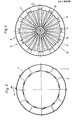
- 2 and 3 give to him know that the lifting blades 2 are arranged at equal intervals in the circumferential direction.
- the lifting blades 2 are arranged offset from one another, so that the amount of fructose captured by a lifting blade is distributed over two lifting blades when transported further in the longitudinal direction of the drum, or vice versa. This results in an intensive mass transfer and thus good heat conduction of the fructose to be dried, which has a favorable influence on the drying process.
- the bearings 3 and 4 serve to support the rotatable drum 1.
- a central warm air pipe 5 is shown, which projects into the drum 1.
- the warm air pipe 5 can be connected to a warm air blower, not shown.
- the hot air generated by the hot air blower is blown along the arrow 6 through the hot air pipe 5 into the drum.
- a cold air blower also not shown, is provided which can be connected to the ring section of the drum 1 which is concentric with the warm air pipe 5, so that the cold air can flow through the annular pipe section of the drum 1 in the direction of the arrow 7.
- the air baffle 8 consists of baffles 10 arranged radially and with the same inclination to the longitudinal axis of the drum, the radial ends of which are held in axially offset planes.
- the ends of the guide plates 10 directed in the direction of the drum axis are attached to a central disk 12 in a radially symmetrical manner.
- the ge to the drum wall directed ends of the baffles 10 are connected to the drum wall via sheet metal sections 14.
- the air guiding device 9 is constructed in the same way as the air guiding device 8 and consists of baffles 11 which are supported in a self-supporting manner at their ends directed towards the drum axis and are connected to sheet metal sections 15 at their ends directed towards the drum wall.
- the disk 12 lies approximately in the same radial plane as the sheet metal sections 15, while the disk 13 is arranged approximately in the radial plane of the sheet metal sections 14.
- the diameter of the disks 12 and 13 is selected so that the guide plates 10 and 11 are inclined relative to one another by an angle of approximately 90 ° and thus in relation to the longitudinal axis of the drum in each case by an angle of approximately 45 °. Due to identical baffles 10 and 11, the air baffles 8 and 9 also correspond, which are directed towards each other and mesh like a comb.
- FIG. 4 shows a plan view of the air guiding devices 8 and 9 in the direction of the longitudinal axis of the drum. It can be seen here that the guide plates 10 and 11 have a trapezoidal shape and almost form a closed surface in their axial projection. 4 reveals that the central disk 12, which is connected to the ends of the guide plates 10 and faces the open end 5a of the hot air pipe 5, has an annular shape, so that the air flowing out of the hot air pipe 6 does not reach one bouncing surface perpendicular to the direction of flow and significantly increasing the air resistance.
- the static mixer rotating with the drum 1, which consists of the air guiding devices 8 and 9, ensures a mixing of those emerging from the warm air pipe and that concentric therewith flowing air.
- the warm air flows out of the warm air pipe 5 at a temperature of approximately 120 ° C.
- the concentrically flowing air has a temperature of around 10 ° C.
- Intensive mixing of these two air quantities of different temperatures by the air guiding devices 8 and 9 results in a largely uniform air temperature of approximately 70 ° C. in the left part of the drum 1 between its free end 1 a and the mixer.
- This section of the drum 1 thus represents a drying zone, while the right section of the drum 1 between its end 1b and the mixer acts as a cooling zone.
- lifting blades 16 and 17 which are inclined relative to the longitudinal axis of the drum and which, when the drum 1 rotates in the direction of the arrow 18 according to FIG. 3, allow the fructose to be transported rapidly through the area turbulent air flows. This prevents the fructose from melting and adhering to the guide plates 10 and 11.
- the task of the material to be dried in the inclined and rotating drum 1 takes place at the end la. From there, the material passes through inclined lifting blades into the chambers formed by the lifting blades 2, as can be seen particularly from FIG. 3. Here, the goods are transported against the air flow, which results in an extended stay in the drying zone and thus good drying.
- the dried material passes through the area of the air guiding devices 8 and 9 along the drum wall, whereby it is guided by the lifting blades 16 and 17.
- the material then reaches the cold air zone and is picked up again by lifting blades 2. After passing through the cooling zone in the direction of the end 1b of the drum 1, the cooled material is removed from the end 1b of the drum 1.
- the drum Due to the static mixer consisting of the air guiding devices 8 and 9, which, like the warm air pipe 8, also rotates with the drum, the drum no longer needs to be divided into two longitudinal sections of different diameters, in contrast to the known solutions. Rather, both the drying zone and the cooling zone can be accommodated in a common drum with the same diameter. There are also no air openings along the drum wall, for example for removing the cold air.
Landscapes
- Chemical & Material Sciences (AREA)
- Life Sciences & Earth Sciences (AREA)
- Biochemistry (AREA)
- Organic Chemistry (AREA)
- Drying Of Solid Materials (AREA)
Applications Claiming Priority (2)
| Application Number | Priority Date | Filing Date | Title |
|---|---|---|---|
| DE19828234134U DE8234134U1 (de) | 1982-12-04 | 1982-12-04 | Vorrichtung zum trocknen und kuehlen von feinkristallinem zucker, insbesondere fructose |
| DE8234134U | 1982-12-04 |
Publications (3)
| Publication Number | Publication Date |
|---|---|
| EP0114939A2 true EP0114939A2 (fr) | 1984-08-08 |
| EP0114939A3 EP0114939A3 (en) | 1984-12-19 |
| EP0114939B1 EP0114939B1 (fr) | 1986-09-03 |
Family
ID=6746222
Family Applications (1)
| Application Number | Title | Priority Date | Filing Date |
|---|---|---|---|
| EP83110553A Expired EP0114939B1 (fr) | 1982-12-04 | 1983-10-22 | Dispositif pour sécher et refroidir du sucre finement cristallin en particulier du fructose |
Country Status (2)
| Country | Link |
|---|---|
| EP (1) | EP0114939B1 (fr) |
| DE (2) | DE8234134U1 (fr) |
Cited By (2)
| Publication number | Priority date | Publication date | Assignee | Title |
|---|---|---|---|---|
| EP0338099A1 (fr) * | 1988-04-16 | 1989-10-25 | Braunschweigische Maschinenbauanstalt AG | Procédé de séchage et de refroidissement de masses de sucre cristallines humides et installation pour la mise en oeuvre de ce procédé |
| US20110099833A1 (en) * | 2008-07-04 | 2011-05-05 | Young Kim | Radial rotary dryer |
Family Cites Families (5)
| Publication number | Priority date | Publication date | Assignee | Title |
|---|---|---|---|---|
| DE281643C (fr) * | ||||
| DE1161820B (de) * | 1959-09-23 | 1964-01-23 | Buettner Werke Ag | Vorrichtung zur Gegenstromtrocknung und -kuehlung von Weisszucker |
| DE1245330B (de) * | 1962-03-20 | 1967-07-27 | Boliden Ab | Vorrichtung zur Behandlung von festem, feinkoernigem oder pulverfoermigem Material mit Fluessigkeit und/oder Gas |
| FR1472759A (fr) * | 1966-03-29 | 1967-03-10 | Buettner Werke Ag | Dispositif pour le séchage et le refroidissement du sucre blanc à contre-courant |
| GB1133543A (en) * | 1967-02-06 | 1968-11-13 | Bartlett Snow Pacific Inc | Combination dryer and cooler |
-
1982
- 1982-12-04 DE DE19828234134U patent/DE8234134U1/de not_active Expired
-
1983
- 1983-10-22 EP EP83110553A patent/EP0114939B1/fr not_active Expired
- 1983-10-22 DE DE8383110553T patent/DE3365889D1/de not_active Expired
Cited By (3)
| Publication number | Priority date | Publication date | Assignee | Title |
|---|---|---|---|---|
| EP0338099A1 (fr) * | 1988-04-16 | 1989-10-25 | Braunschweigische Maschinenbauanstalt AG | Procédé de séchage et de refroidissement de masses de sucre cristallines humides et installation pour la mise en oeuvre de ce procédé |
| US20110099833A1 (en) * | 2008-07-04 | 2011-05-05 | Young Kim | Radial rotary dryer |
| US8601711B2 (en) * | 2008-07-04 | 2013-12-10 | Young Kim | Radial rotary dryer |
Also Published As
| Publication number | Publication date |
|---|---|
| EP0114939A3 (en) | 1984-12-19 |
| DE8234134U1 (de) | 1983-05-26 |
| DE3365889D1 (en) | 1986-10-09 |
| EP0114939B1 (fr) | 1986-09-03 |
Similar Documents
| Publication | Publication Date | Title |
|---|---|---|
| DE2522106B2 (de) | Vorrichtung zum kontinuierlichen Mischen fließfähiger Stoffe und Verfahren zum Herstellen eines Mischeinsatzes | |
| DE3017431C2 (de) | Lüftungsvorrichtung für Räume mit zwei getrennten Strömungswegen zur Be- und Entlüftung | |
| DE1269145B (de) | Waermeaustauscher | |
| DE2802876A1 (de) | Mischwerk fuer mischmaschinen | |
| DE2739998B2 (de) | Strangpreßvorrichtung zur Herstellung von geschäumtem Kunststoff | |
| DE3013900C2 (de) | Einrichtung zum Trocknen von feuchtem Material | |
| DE69521908T2 (de) | Statische luftmischungsvorrichtung | |
| DE2811489C2 (de) | Statischer Mischer | |
| EP0114939B1 (fr) | Dispositif pour sécher et refroidir du sucre finement cristallin en particulier du fructose | |
| DE3729032A1 (de) | Drehtrommel | |
| DE2220534C3 (de) | Drehströmungswirbler zur Sichtung und Abscheidung feinkörniger Partikel | |
| DE475509C (de) | Schalldaempfender Auspufftopf mit mehreren hintereinander angeordneten rohrfoermigen Einheitsstuecken | |
| DE3045731A1 (de) | Waermetauscher | |
| EP1525067B1 (fr) | Chambre de traitement d'un systeme de traitement thermique de plaquettes conductrices | |
| DE2731289A1 (de) | Gestaltung des schmutzgaseinlasses fuer einen zyklonabscheider | |
| DE10138333A1 (de) | Vorrichtung zum Auspressen fließfähiger Substanzen | |
| DE8518384U1 (de) | Rotierender Wärmeaustauscher | |
| DE3217015C2 (de) | Windform, insbesondere für Hochöfen | |
| EP0166190A2 (fr) | Dispositif de nettoyage pour un échangeur de chaleur de régénération | |
| EP0536498B1 (fr) | Appareil de chauffage et/ou de refroidissement | |
| EP1555068B1 (fr) | Cloison de broyeur tubulaire et méthode de broyage utilisant un tel broyeur | |
| DE2715515C3 (de) | Materialaustragsanordnung für ein Drehmahlwerk | |
| DE3802791A1 (de) | Vorrichtung zum durchstroemenden behandeln von textilgut, papier od. dgl. | |
| DE2933291A1 (de) | Probenteiler zur teilung eines materialstromes | |
| DE102015212353B3 (de) | Vorrichtung und Verfahren zum Vertropfen eines fließfähigen Produkts |
Legal Events
| Date | Code | Title | Description |
|---|---|---|---|
| PUAI | Public reference made under article 153(3) epc to a published international application that has entered the european phase |
Free format text: ORIGINAL CODE: 0009012 |
|
| AK | Designated contracting states |
Designated state(s): DE FR GB NL |
|
| PUAL | Search report despatched |
Free format text: ORIGINAL CODE: 0009013 |
|
| AK | Designated contracting states |
Designated state(s): DE FR GB NL |
|
| 17P | Request for examination filed |
Effective date: 19850130 |
|
| GRAA | (expected) grant |
Free format text: ORIGINAL CODE: 0009210 |
|
| AK | Designated contracting states |
Kind code of ref document: B1 Designated state(s): DE FR GB NL |
|
| REF | Corresponds to: |
Ref document number: 3365889 Country of ref document: DE Date of ref document: 19861009 |
|
| ET | Fr: translation filed | ||
| PLBE | No opposition filed within time limit |
Free format text: ORIGINAL CODE: 0009261 |
|
| STAA | Information on the status of an ep patent application or granted ep patent |
Free format text: STATUS: NO OPPOSITION FILED WITHIN TIME LIMIT |
|
| 26N | No opposition filed | ||
| PGFP | Annual fee paid to national office [announced via postgrant information from national office to epo] |
Ref country code: NL Payment date: 19931031 Year of fee payment: 11 |
|
| PG25 | Lapsed in a contracting state [announced via postgrant information from national office to epo] |
Ref country code: NL Effective date: 19950501 |
|
| NLV4 | Nl: lapsed or anulled due to non-payment of the annual fee | ||
| PGFP | Annual fee paid to national office [announced via postgrant information from national office to epo] |
Ref country code: FR Payment date: 19960828 Year of fee payment: 14 |
|
| PGFP | Annual fee paid to national office [announced via postgrant information from national office to epo] |
Ref country code: GB Payment date: 19961014 Year of fee payment: 14 |
|
| PGFP | Annual fee paid to national office [announced via postgrant information from national office to epo] |
Ref country code: DE Payment date: 19961016 Year of fee payment: 14 |
|
| PG25 | Lapsed in a contracting state [announced via postgrant information from national office to epo] |
Ref country code: GB Free format text: LAPSE BECAUSE OF NON-PAYMENT OF DUE FEES Effective date: 19971022 |
|
| PG25 | Lapsed in a contracting state [announced via postgrant information from national office to epo] |
Ref country code: FR Free format text: THE PATENT HAS BEEN ANNULLED BY A DECISION OF A NATIONAL AUTHORITY Effective date: 19971031 |
|
| GBPC | Gb: european patent ceased through non-payment of renewal fee |
Effective date: 19971022 |
|
| PG25 | Lapsed in a contracting state [announced via postgrant information from national office to epo] |
Ref country code: DE Free format text: LAPSE BECAUSE OF NON-PAYMENT OF DUE FEES Effective date: 19980701 |
|
| REG | Reference to a national code |
Ref country code: FR Ref legal event code: ST |