EP0115032B1 - Betätiger für ein mechanisches Mischventil - Google Patents
Betätiger für ein mechanisches Mischventil Download PDFInfo
- Publication number
- EP0115032B1 EP0115032B1 EP83112850A EP83112850A EP0115032B1 EP 0115032 B1 EP0115032 B1 EP 0115032B1 EP 83112850 A EP83112850 A EP 83112850A EP 83112850 A EP83112850 A EP 83112850A EP 0115032 B1 EP0115032 B1 EP 0115032B1
- Authority
- EP
- European Patent Office
- Prior art keywords
- axis
- lever
- control
- control shaft
- handle
- Prior art date
- Legal status (The legal status is an assumption and is not a legal conclusion. Google has not performed a legal analysis and makes no representation as to the accuracy of the status listed.)
- Expired
Links
Images

Classifications
-
- F—MECHANICAL ENGINEERING; LIGHTING; HEATING; WEAPONS; BLASTING
- F16—ENGINEERING ELEMENTS AND UNITS; GENERAL MEASURES FOR PRODUCING AND MAINTAINING EFFECTIVE FUNCTIONING OF MACHINES OR INSTALLATIONS; THERMAL INSULATION IN GENERAL
- F16K—VALVES; TAPS; COCKS; ACTUATING-FLOATS; DEVICES FOR VENTING OR AERATING
- F16K31/00—Actuating devices; Operating means; Releasing devices
- F16K31/44—Mechanical actuating means
- F16K31/60—Handles
- F16K31/605—Handles for single handle mixing valves
-
- F—MECHANICAL ENGINEERING; LIGHTING; HEATING; WEAPONS; BLASTING
- F16—ENGINEERING ELEMENTS AND UNITS; GENERAL MEASURES FOR PRODUCING AND MAINTAINING EFFECTIVE FUNCTIONING OF MACHINES OR INSTALLATIONS; THERMAL INSULATION IN GENERAL
- F16K—VALVES; TAPS; COCKS; ACTUATING-FLOATS; DEVICES FOR VENTING OR AERATING
- F16K11/00—Multiple-way valves, e.g. mixing valves; Pipe fittings incorporating such valves
- F16K11/02—Multiple-way valves, e.g. mixing valves; Pipe fittings incorporating such valves with all movable sealing faces moving as one unit
- F16K11/06—Multiple-way valves, e.g. mixing valves; Pipe fittings incorporating such valves with all movable sealing faces moving as one unit comprising only sliding valves, i.e. sliding closure elements
- F16K11/078—Multiple-way valves, e.g. mixing valves; Pipe fittings incorporating such valves with all movable sealing faces moving as one unit comprising only sliding valves, i.e. sliding closure elements with pivoted and linearly movable closure members
- F16K11/0782—Single-lever operated mixing valves with closure members having flat sealing faces
Definitions
- the present invention relates to a control for a mechanical mixer of the type comprising ceramic plates displaceable relative to one another in translation and in rotation.
- One of the relative movements of the pads controls the temperature of the water leaving the mixer, while the other controls the flow of water.
- a mixer is for example such as that described in document CH-A-643641
- a mixer of this type is illustrated in Figure 1 of the accompanying drawing.
- the single control lever 1 which drives one of the ceramic plates in translation and in rotation relative to the other plate by means of a control pin is illustrated in solid lines in an extreme position and in broken lines in the another extreme rocking position. Due to the vertical tilting of the lever 1, it is noted that the lever arm useful for the rotation control gradually decreases from one extreme position to the other of the lever 1 for which this lever arm a is minimum. Under these conditions, we immediately notice the major drawback of such mixers which is that it requires an increasing force for the rotation of the control lever 1 as a function of the degree of tilting of this lever.
- the object of the present invention is to remedy this drawback and thus to provide a control for a mechanical mixer with a tiltable and rotary control lever which is distinguished by the characteristics listed in claim 1.
- FIG. 2 illustrates a first embodiment of a mechanical mixer, certain parts being seen in section.
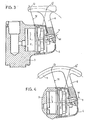
- FIG. 3 illustrates the mixer of FIG. 1 provided with a second embodiment of its control.
- FIG. 4 still illustrates the same mixer, but equipped with a third embodiment of its control.
- the mixer 2 of the type with ceramic plates displaceable in rotation and in translation, will not be described here since it is existing and described for example in the Swiss patent application mentioned in the introduction.
- This mixer 2 is conventionally mounted in the body of a battery 3 comprising the pipes for supplying cold and hot water as well as the pipe supplying a neck (not shown).
- a protective cap 4 covers the part of the mixer 2 emerging from the body of the battery 3.
- the mechanical mixer comprises in known manner a control axis 5 pivoted on one of the ceramic plates along an axis 0 orthogonally cutting the longitudinal axis L of the mixer.
- M represents the axis of the control axis 5, located in the same plane as the longitudinal axis L of the mixer and passing through the intersection of the axes L and O.
- the control of the illustrated mixer also comprises a control lever 6 integral with the control axis 5 making it possible to drive the latter in a rotation around the axis M to cause the relative rotation of the ceramic plates for example and also in rotation about the axis 0 to cause the translation of said ceramic plates.
- This control lever 6 has a shape capable of defining a handle or gripping member, here a bent end, and that a point Q of this handle intersects a straight line N perpendicular to the axis M of the control axis 5.
- This straight line N is also perpendicular to the axis 0 and lies in the same plane as the axes L and M.
- This construction allows a minimum size of the control lever 6 for a determined control force.
- the lever 6 has the general shape of a T whose bar forms the handle and also has a point Q located on this handle and on the right N perpendicular to the axis M of the control axis 5.
- the point Q of this lever goes Q 'during its tilting and here also the lever arm relative to the axis L of the mixer remains practically the same regardless of the position of the lever 6.
- control lever 6 comprises an arcuate handle 7 extending over an arc of a circle with center O.
- the handle due to the shape of the handle, there is always, whatever the position of the lever, a point on said handle situated on a perpendicular to the axis L of the mixer passing through point O. Therefore, for any position of lever 6 the lever arm, determining the control force in rotation, is constant.
- the handle of the lever 6 facilitates its handling.
Landscapes
- Engineering & Computer Science (AREA)
- General Engineering & Computer Science (AREA)
- Mechanical Engineering (AREA)
- Multiple-Way Valves (AREA)
- Processing And Handling Of Plastics And Other Materials For Molding In General (AREA)
- Mechanically-Actuated Valves (AREA)
Claims (5)
Priority Applications (1)
| Application Number | Priority Date | Filing Date | Title |
|---|---|---|---|
| AT83112850T ATE20961T1 (de) | 1983-01-28 | 1983-12-20 | Betaetiger fuer ein mechanisches mischventil. |
Applications Claiming Priority (2)
| Application Number | Priority Date | Filing Date | Title |
|---|---|---|---|
| CH491/83 | 1983-01-28 | ||
| CH491/83A CH651364A5 (fr) | 1983-01-28 | 1983-01-28 | Dispositif de commande pour melangeur mecanique. |
Publications (3)
| Publication Number | Publication Date |
|---|---|
| EP0115032A2 EP0115032A2 (de) | 1984-08-08 |
| EP0115032A3 EP0115032A3 (en) | 1984-08-22 |
| EP0115032B1 true EP0115032B1 (de) | 1986-07-23 |
Family
ID=4188225
Family Applications (1)
| Application Number | Title | Priority Date | Filing Date |
|---|---|---|---|
| EP83112850A Expired EP0115032B1 (de) | 1983-01-28 | 1983-12-20 | Betätiger für ein mechanisches Mischventil |
Country Status (4)
| Country | Link |
|---|---|
| EP (1) | EP0115032B1 (de) |
| AT (1) | ATE20961T1 (de) |
| CH (1) | CH651364A5 (de) |
| DE (2) | DE115032T1 (de) |
Families Citing this family (2)
| Publication number | Priority date | Publication date | Assignee | Title |
|---|---|---|---|---|
| DE19649774A1 (de) * | 1996-01-23 | 1998-06-04 | Grohe Kg Hans | Sanitärarmatur |
| GB2418972B (en) * | 2005-05-25 | 2007-01-10 | Diana Turner | Improvements to sanitary tap assemblies |
Citations (1)
| Publication number | Priority date | Publication date | Assignee | Title |
|---|---|---|---|---|
| CH643641A5 (fr) * | 1981-11-02 | 1984-06-15 | Kugler Fonderie Robinetterie | Melangeur mecanique a plaquettes ceramiques a monocommande. |
Family Cites Families (1)
| Publication number | Priority date | Publication date | Assignee | Title |
|---|---|---|---|---|
| US2977986A (en) * | 1957-02-04 | 1961-04-04 | Price Pfister Brass Mfg | Single-handled valve |
-
1983
- 1983-01-28 CH CH491/83A patent/CH651364A5/fr not_active IP Right Cessation
- 1983-12-20 EP EP83112850A patent/EP0115032B1/de not_active Expired
- 1983-12-20 DE DE198383112850T patent/DE115032T1/de active Pending
- 1983-12-20 AT AT83112850T patent/ATE20961T1/de not_active IP Right Cessation
- 1983-12-20 DE DE8383112850T patent/DE3364777D1/de not_active Expired
Patent Citations (1)
| Publication number | Priority date | Publication date | Assignee | Title |
|---|---|---|---|---|
| CH643641A5 (fr) * | 1981-11-02 | 1984-06-15 | Kugler Fonderie Robinetterie | Melangeur mecanique a plaquettes ceramiques a monocommande. |
Also Published As
| Publication number | Publication date |
|---|---|
| ATE20961T1 (de) | 1986-08-15 |
| EP0115032A3 (en) | 1984-08-22 |
| DE115032T1 (de) | 1984-12-06 |
| DE3364777D1 (en) | 1986-08-28 |
| CH651364A5 (fr) | 1985-09-13 |
| EP0115032A2 (de) | 1984-08-08 |
Similar Documents
| Publication | Publication Date | Title |
|---|---|---|
| EP0541468B1 (de) | Vorrichtung für ein automatisches Ventil | |
| EP0070230A1 (de) | Entkupplungseinrichtung für Zugvorrichtung, durch welche ein Seil geführt ist | |
| FR2557533A1 (fr) | Dispositif de commande de frein d'une bicyclette | |
| CA2276858A1 (fr) | Appareil anti-chute sur cable vertical | |
| FR2632266A1 (fr) | Support pour le levier d'actionnement de frein et le levier de changement de vitesses de bicyclettes et analogues | |
| EP0115032B1 (de) | Betätiger für ein mechanisches Mischventil | |
| EP0181027A2 (de) | Bremse einer Angelwinde | |
| US4624385A (en) | Actuating device for the cap of a spout of a whistling kettle | |
| EP0010038A1 (de) | Löt- bzw. Schweissbrenner für zwei Gase | |
| EP0867570B1 (de) | Einbauspülkasten zur Top- oder Frontbetätigung | |
| EP1585868B1 (de) | Entleerungssteuervorrichtung | |
| EP3623273B1 (de) | Haltevorrichtung eines gasdrehgriffes | |
| FR2630181A1 (fr) | Robinet melangeur a butees variables | |
| JP2000289692A (ja) | 船外機 | |
| FR2738710A1 (fr) | Taille-haie a poignees multi-positions | |
| FR2662966A1 (fr) | Dispositif pour la mesure de l'angle de serrage sur une cle avec rallonge, par rapport a un organe oriente dans une direction fixe. | |
| EP0519811A1 (de) | Bowdenzugsteuergehäuse | |
| EP0289541A1 (de) | Antriebsvorrichtung für rolladen | |
| EP1010825A3 (de) | Ab- und Überlaufgarnitur | |
| FR2505009A1 (fr) | Mecanisme a levier pour commande a plaquettes ceramiques de melangeur sanitaire | |
| EP0363657A2 (de) | Wassermisch- und Verteilereinrichtung, insbesondere für Badewannen, Duschen und ähnliche Vorrichtungen | |
| FR2460103A2 (fr) | Dispositif de commande d'arrosage | |
| EP0185644A3 (de) | Antriebsvorrichtung für Vorhänge | |
| EP1323584A3 (de) | Versenkbarer Halter | |
| FR2466692A1 (fr) | Robinet melangeur a commande par excentrique |
Legal Events
| Date | Code | Title | Description |
|---|---|---|---|
| PUAI | Public reference made under article 153(3) epc to a published international application that has entered the european phase |
Free format text: ORIGINAL CODE: 0009012 |
|
| PUAL | Search report despatched |
Free format text: ORIGINAL CODE: 0009013 |
|
| AK | Designated contracting states |
Designated state(s): AT CH DE FR GB LI NL |
|
| AK | Designated contracting states |
Designated state(s): AT CH DE FR GB LI NL |
|
| TCAT | At: translation of patent claims filed | ||
| TCNL | Nl: translation of patent claims filed | ||
| 17P | Request for examination filed |
Effective date: 19840928 |
|
| DET | De: translation of patent claims | ||
| GRAA | (expected) grant |
Free format text: ORIGINAL CODE: 0009210 |
|
| AK | Designated contracting states |
Kind code of ref document: B1 Designated state(s): AT CH DE FR GB LI NL |
|
| REF | Corresponds to: |
Ref document number: 20961 Country of ref document: AT Date of ref document: 19860815 Kind code of ref document: T |
|
| REF | Corresponds to: |
Ref document number: 3364777 Country of ref document: DE Date of ref document: 19860828 |
|
| PLBE | No opposition filed within time limit |
Free format text: ORIGINAL CODE: 0009261 |
|
| STAA | Information on the status of an ep patent application or granted ep patent |
Free format text: STATUS: NO OPPOSITION FILED WITHIN TIME LIMIT |
|
| 26N | No opposition filed | ||
| PGFP | Annual fee paid to national office [announced via postgrant information from national office to epo] |
Ref country code: AT Payment date: 19891122 Year of fee payment: 7 |
|
| PGFP | Annual fee paid to national office [announced via postgrant information from national office to epo] |
Ref country code: FR Payment date: 19891124 Year of fee payment: 7 |
|
| PGFP | Annual fee paid to national office [announced via postgrant information from national office to epo] |
Ref country code: CH Payment date: 19891127 Year of fee payment: 7 |
|
| PGFP | Annual fee paid to national office [announced via postgrant information from national office to epo] |
Ref country code: NL Payment date: 19891231 Year of fee payment: 7 Ref country code: GB Payment date: 19891231 Year of fee payment: 7 |
|
| PGFP | Annual fee paid to national office [announced via postgrant information from national office to epo] |
Ref country code: DE Payment date: 19900122 Year of fee payment: 7 |
|
| PG25 | Lapsed in a contracting state [announced via postgrant information from national office to epo] |
Ref country code: GB Effective date: 19901220 Ref country code: AT Effective date: 19901220 |
|
| PG25 | Lapsed in a contracting state [announced via postgrant information from national office to epo] |
Ref country code: LI Effective date: 19901231 Ref country code: CH Effective date: 19901231 |
|
| PG25 | Lapsed in a contracting state [announced via postgrant information from national office to epo] |
Ref country code: NL Effective date: 19910701 |
|
| GBPC | Gb: european patent ceased through non-payment of renewal fee | ||
| NLV4 | Nl: lapsed or anulled due to non-payment of the annual fee | ||
| PG25 | Lapsed in a contracting state [announced via postgrant information from national office to epo] |
Ref country code: FR Effective date: 19910830 |
|
| REG | Reference to a national code |
Ref country code: CH Ref legal event code: PL |
|
| PG25 | Lapsed in a contracting state [announced via postgrant information from national office to epo] |
Ref country code: DE Effective date: 19910903 |
|
| REG | Reference to a national code |
Ref country code: FR Ref legal event code: ST |