EP0115181B1 - Verfahren zum Betreiben eines Tintenstrahlapparates - Google Patents
Verfahren zum Betreiben eines Tintenstrahlapparates Download PDFInfo
- Publication number
- EP0115181B1 EP0115181B1 EP83307852A EP83307852A EP0115181B1 EP 0115181 B1 EP0115181 B1 EP 0115181B1 EP 83307852 A EP83307852 A EP 83307852A EP 83307852 A EP83307852 A EP 83307852A EP 0115181 B1 EP0115181 B1 EP 0115181B1
- Authority
- EP
- European Patent Office
- Prior art keywords
- ink
- droplet
- orifice
- chamber
- pulse
- Prior art date
- Legal status (The legal status is an assumption and is not a legal conclusion. Google has not performed a legal analysis and makes no representation as to the accuracy of the status listed.)
- Expired
Links
- 238000000034 method Methods 0.000 title claims abstract description 30
- 230000000977 initiatory effect Effects 0.000 claims abstract description 5
- 210000003041 ligament Anatomy 0.000 claims description 15
- 230000003247 decreasing effect Effects 0.000 claims description 6
- 238000007493 shaping process Methods 0.000 claims description 3
- 238000011038 discontinuous diafiltration by volume reduction Methods 0.000 claims description 2
- 239000000976 ink Substances 0.000 description 136
- 230000005499 meniscus Effects 0.000 description 8
- 238000004519 manufacturing process Methods 0.000 description 6
- 230000000694 effects Effects 0.000 description 5
- 238000007639 printing Methods 0.000 description 4
- 230000000630 rising effect Effects 0.000 description 4
- 230000008901 benefit Effects 0.000 description 3
- 238000010304 firing Methods 0.000 description 3
- 230000009467 reduction Effects 0.000 description 3
- 230000009471 action Effects 0.000 description 2
- 230000015572 biosynthetic process Effects 0.000 description 2
- 230000008602 contraction Effects 0.000 description 2
- 230000018109 developmental process Effects 0.000 description 2
- 238000010586 diagram Methods 0.000 description 2
- 238000002474 experimental method Methods 0.000 description 2
- 230000033001 locomotion Effects 0.000 description 2
- 239000012528 membrane Substances 0.000 description 2
- 239000003190 viscoelastic substance Substances 0.000 description 2
- 230000032683 aging Effects 0.000 description 1
- 230000015556 catabolic process Effects 0.000 description 1
- 238000011109 contamination Methods 0.000 description 1
- 230000008878 coupling Effects 0.000 description 1
- 238000010168 coupling process Methods 0.000 description 1
- 238000005859 coupling reaction Methods 0.000 description 1
- 238000006731 degradation reaction Methods 0.000 description 1
- 238000005516 engineering process Methods 0.000 description 1
- 230000037406 food intake Effects 0.000 description 1
- 238000009472 formulation Methods 0.000 description 1
- 239000012634 fragment Substances 0.000 description 1
- 230000028161 membrane depolarization Effects 0.000 description 1
- 239000000203 mixture Substances 0.000 description 1
- 230000003287 optical effect Effects 0.000 description 1
- 239000002245 particle Substances 0.000 description 1
- 230000004044 response Effects 0.000 description 1
- 238000000926 separation method Methods 0.000 description 1
- 238000004904 shortening Methods 0.000 description 1
- 238000005507 spraying Methods 0.000 description 1
- 230000007480 spreading Effects 0.000 description 1
- 238000003892 spreading Methods 0.000 description 1
- 230000035882 stress Effects 0.000 description 1
- 230000007704 transition Effects 0.000 description 1
Images



Classifications
-
- B—PERFORMING OPERATIONS; TRANSPORTING
- B41—PRINTING; LINING MACHINES; TYPEWRITERS; STAMPS
- B41J—TYPEWRITERS; SELECTIVE PRINTING MECHANISMS, i.e. MECHANISMS PRINTING OTHERWISE THAN FROM A FORME; CORRECTION OF TYPOGRAPHICAL ERRORS
- B41J2/00—Typewriters or selective printing mechanisms characterised by the printing or marking process for which they are designed
- B41J2/005—Typewriters or selective printing mechanisms characterised by the printing or marking process for which they are designed characterised by bringing liquid or particles selectively into contact with a printing material
- B41J2/01—Ink jet
- B41J2/015—Ink jet characterised by the jet generation process
- B41J2/04—Ink jet characterised by the jet generation process generating single droplets or particles on demand
- B41J2/045—Ink jet characterised by the jet generation process generating single droplets or particles on demand by pressure, e.g. electromechanical transducers
- B41J2/04501—Control methods or devices therefor, e.g. driver circuits, control circuits
- B41J2/04516—Control methods or devices therefor, e.g. driver circuits, control circuits preventing formation of satellite drops
-
- B—PERFORMING OPERATIONS; TRANSPORTING
- B41—PRINTING; LINING MACHINES; TYPEWRITERS; STAMPS
- B41J—TYPEWRITERS; SELECTIVE PRINTING MECHANISMS, i.e. MECHANISMS PRINTING OTHERWISE THAN FROM A FORME; CORRECTION OF TYPOGRAPHICAL ERRORS
- B41J2/00—Typewriters or selective printing mechanisms characterised by the printing or marking process for which they are designed
- B41J2/005—Typewriters or selective printing mechanisms characterised by the printing or marking process for which they are designed characterised by bringing liquid or particles selectively into contact with a printing material
- B41J2/01—Ink jet
- B41J2/015—Ink jet characterised by the jet generation process
- B41J2/04—Ink jet characterised by the jet generation process generating single droplets or particles on demand
- B41J2/045—Ink jet characterised by the jet generation process generating single droplets or particles on demand by pressure, e.g. electromechanical transducers
- B41J2/04501—Control methods or devices therefor, e.g. driver circuits, control circuits
- B41J2/04528—Control methods or devices therefor, e.g. driver circuits, control circuits aiming at warming up the head
-
- B—PERFORMING OPERATIONS; TRANSPORTING
- B41—PRINTING; LINING MACHINES; TYPEWRITERS; STAMPS
- B41J—TYPEWRITERS; SELECTIVE PRINTING MECHANISMS, i.e. MECHANISMS PRINTING OTHERWISE THAN FROM A FORME; CORRECTION OF TYPOGRAPHICAL ERRORS
- B41J2/00—Typewriters or selective printing mechanisms characterised by the printing or marking process for which they are designed
- B41J2/005—Typewriters or selective printing mechanisms characterised by the printing or marking process for which they are designed characterised by bringing liquid or particles selectively into contact with a printing material
- B41J2/01—Ink jet
- B41J2/015—Ink jet characterised by the jet generation process
- B41J2/04—Ink jet characterised by the jet generation process generating single droplets or particles on demand
- B41J2/045—Ink jet characterised by the jet generation process generating single droplets or particles on demand by pressure, e.g. electromechanical transducers
- B41J2/04501—Control methods or devices therefor, e.g. driver circuits, control circuits
- B41J2/04573—Timing; Delays
-
- B—PERFORMING OPERATIONS; TRANSPORTING
- B41—PRINTING; LINING MACHINES; TYPEWRITERS; STAMPS
- B41J—TYPEWRITERS; SELECTIVE PRINTING MECHANISMS, i.e. MECHANISMS PRINTING OTHERWISE THAN FROM A FORME; CORRECTION OF TYPOGRAPHICAL ERRORS
- B41J2/00—Typewriters or selective printing mechanisms characterised by the printing or marking process for which they are designed
- B41J2/005—Typewriters or selective printing mechanisms characterised by the printing or marking process for which they are designed characterised by bringing liquid or particles selectively into contact with a printing material
- B41J2/01—Ink jet
- B41J2/015—Ink jet characterised by the jet generation process
- B41J2/04—Ink jet characterised by the jet generation process generating single droplets or particles on demand
- B41J2/045—Ink jet characterised by the jet generation process generating single droplets or particles on demand by pressure, e.g. electromechanical transducers
- B41J2/04501—Control methods or devices therefor, e.g. driver circuits, control circuits
- B41J2/04581—Control methods or devices therefor, e.g. driver circuits, control circuits controlling heads based on piezoelectric elements
-
- B—PERFORMING OPERATIONS; TRANSPORTING
- B41—PRINTING; LINING MACHINES; TYPEWRITERS; STAMPS
- B41J—TYPEWRITERS; SELECTIVE PRINTING MECHANISMS, i.e. MECHANISMS PRINTING OTHERWISE THAN FROM A FORME; CORRECTION OF TYPOGRAPHICAL ERRORS
- B41J2/00—Typewriters or selective printing mechanisms characterised by the printing or marking process for which they are designed
- B41J2/005—Typewriters or selective printing mechanisms characterised by the printing or marking process for which they are designed characterised by bringing liquid or particles selectively into contact with a printing material
- B41J2/01—Ink jet
- B41J2/015—Ink jet characterised by the jet generation process
- B41J2/04—Ink jet characterised by the jet generation process generating single droplets or particles on demand
- B41J2/045—Ink jet characterised by the jet generation process generating single droplets or particles on demand by pressure, e.g. electromechanical transducers
- B41J2/04501—Control methods or devices therefor, e.g. driver circuits, control circuits
- B41J2/04588—Control methods or devices therefor, e.g. driver circuits, control circuits using a specific waveform
-
- B—PERFORMING OPERATIONS; TRANSPORTING
- B41—PRINTING; LINING MACHINES; TYPEWRITERS; STAMPS
- B41J—TYPEWRITERS; SELECTIVE PRINTING MECHANISMS, i.e. MECHANISMS PRINTING OTHERWISE THAN FROM A FORME; CORRECTION OF TYPOGRAPHICAL ERRORS
- B41J2/00—Typewriters or selective printing mechanisms characterised by the printing or marking process for which they are designed
- B41J2/005—Typewriters or selective printing mechanisms characterised by the printing or marking process for which they are designed characterised by bringing liquid or particles selectively into contact with a printing material
- B41J2/01—Ink jet
- B41J2/015—Ink jet characterised by the jet generation process
- B41J2/04—Ink jet characterised by the jet generation process generating single droplets or particles on demand
- B41J2/045—Ink jet characterised by the jet generation process generating single droplets or particles on demand by pressure, e.g. electromechanical transducers
- B41J2/04501—Control methods or devices therefor, e.g. driver circuits, control circuits
- B41J2/0459—Height of the driving signal being adjusted
-
- B—PERFORMING OPERATIONS; TRANSPORTING
- B41—PRINTING; LINING MACHINES; TYPEWRITERS; STAMPS
- B41J—TYPEWRITERS; SELECTIVE PRINTING MECHANISMS, i.e. MECHANISMS PRINTING OTHERWISE THAN FROM A FORME; CORRECTION OF TYPOGRAPHICAL ERRORS
- B41J2/00—Typewriters or selective printing mechanisms characterised by the printing or marking process for which they are designed
- B41J2/005—Typewriters or selective printing mechanisms characterised by the printing or marking process for which they are designed characterised by bringing liquid or particles selectively into contact with a printing material
- B41J2/01—Ink jet
- B41J2/015—Ink jet characterised by the jet generation process
- B41J2/04—Ink jet characterised by the jet generation process generating single droplets or particles on demand
- B41J2/045—Ink jet characterised by the jet generation process generating single droplets or particles on demand by pressure, e.g. electromechanical transducers
- B41J2/04501—Control methods or devices therefor, e.g. driver circuits, control circuits
- B41J2/04593—Dot-size modulation by changing the size of the drop
-
- B—PERFORMING OPERATIONS; TRANSPORTING
- B41—PRINTING; LINING MACHINES; TYPEWRITERS; STAMPS
- B41J—TYPEWRITERS; SELECTIVE PRINTING MECHANISMS, i.e. MECHANISMS PRINTING OTHERWISE THAN FROM A FORME; CORRECTION OF TYPOGRAPHICAL ERRORS
- B41J2/00—Typewriters or selective printing mechanisms characterised by the printing or marking process for which they are designed
- B41J2/005—Typewriters or selective printing mechanisms characterised by the printing or marking process for which they are designed characterised by bringing liquid or particles selectively into contact with a printing material
- B41J2/01—Ink jet
- B41J2/135—Nozzles
- B41J2/14—Structure thereof only for on-demand ink jet heads
- B41J2002/14387—Front shooter
Definitions
- the field of the present invention relates generally to ink jet apparatus, and more specifically to a method for operating an ink jet apparatus to substantially eliminate instabilities associated with the ejection of ink droplets.
- Aiming error can also be substantially reduced by increasing the droplet velocity because the physical and surface energy irregularities have a proportionally smaller effect on droplets travelling at a higher velocity. It has also been recognized in the prior art that the contribution to placement error due to velocity variations (Av from channel to channel), could theoretically be reduced by increasing velocity, provided that Av remains at the same value relative to lower velocity operation. To counter or reduce placement error problems at low velocity, the present inventor attempted to increase velocity of the ink droplets. However, attempts in the prior art to so increase the velocity resulted in air ingestion and spraying of the ink.
- US-A-4. 112 433 describes a method for operating an ink jet device wherein the ink jet is provided with a meniscus dampening means to shorten the time of meniscus vibration and thereby increase the frequency at which droplets may be expressed through the outlet orifice.
- a first voltage is applied to a piezoelectric plate to exert a stress on an associated membrane, causing the membrane to deform so as to decrease the volume of an associated ink chamber.
- a second voltage is applied at a predetermined time after the application of the first voltage to effect a second pressure increase in the ink chamber.
- US-A-4 112 433 discloses, however, that the second pressure increase must effect a pressure front which arrives within an effective meniscus dampening vicinity of the ink jet orifice at substantially the same instant that the droplet leaves the orifice; in this manner, the pressure front is said to dampen the full period of meniscus vibration.
- Such a mode of operation does not address the problems associated with ligament length discussed hereinbefore, as there is no meniscus formed (and thus, no "meniscus vibration" of the type to which the above-noted document is directed) until after the droplet has broken away. Therefore, US ⁇ A ⁇ 4112 433 does not provide a solution to the problems addressed by the present invention, and is totally silent on the issure of ligament length and adherence to the droplet.
- the present inventor recognized that by operating ink jet apparatus for producing ink droplets in a "high velocity" range of operation, typically from 3.0 meters per second to about 50 metres per second, placement error problems should be greatly reduced. He also recognized that the aiming error and velocity error Av components of the placement error should be substantially reduced at velocities in the upper end of the high velocity range of operation. Also, he observed that reliability, droplet placement accuracy, and print quality is improved by operating an ink jet with relatively high viscosity inks (typically 14 cps) in the high velocity region. However, he encountered problems in operating ink jet apparatus for producing high velocity ink droplets.
- the present invention provides a method for operating an ink jet apparatus for obtaining high velocity ink droplets while avoiding the problems previously mentioned.
- the invention provides a method for operating an ink jet device including a chamber for containing ink, an orifice associated with said chamber, and transducer means coupled to said chamber, said transducer means being operable for producing a pressure disturbance within said chamber for ejecting an ink droplet from within said orifice, said method comprising the steps of:
- the invention provides a method of operating an ink jet device including a chamber for containing ink, an orifice associated with said chamber, an ink supply reservoir coupled to said chamber, and transducer means coupled to said chamber, said transducer means being responsive to an electrical pulse for effectively increasing the volume of said chamber, and to the termination of said pulse for effectively decreasing the volume of said chamber, said method comprising the steps of:
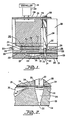
- the illustrative ink jet apparatus includes a chamber 200 having an orifice 202 for ejecting droplets of ink in response to the state of energization of a transducer 204 for each jet in an array of such jets (see Fig. 3).
- the transducer 204 expands and contracts (in directions indicated by the arrows in Fig. 2) along its axis of elongation, and the movement is coupled to the chamber 200 by coupling means 206 which includes a foot 207, a visco-elastic material 208 juxtaposed to the foot 207, and a diaphragm 210 which is preloaded to the position shown in Figures 1 and 2.
- Ink flows into the chamber 200 form an unpressurized reservoir 212 through restricted inlet means their deenergized states as shown in Fig. 4.
- the drive signals are terminated in a step like fashion, causing the transducers 204 to very rapidly expand along their elongated axis, whereby via the visco-elastic material 208 the feet 207 of the transducers 204 push against the area of the diaphragm 210 beneath them, causing a rapid contraction or reduction of the volume of the associated chamber or chambers 200.
- this rapid reduction in the volume of the associated chambers 200 creates a pressure pulse or positive pressure disturbance within the chambers 200, causing an ink droplet to be ejected from the associated orifices 202.
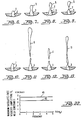
- Figures 6 through 9 show various stages in the production of an ink droplet during low velocity operation of an ink jet apparatus under substantially ideal conditions.
- ink or the ink meniscus 1 begins to emerge from the orifice 3 of the ink jet.
- a discernable ink droplet 5 begins to form as shown in Figure 7.
- the formation of the ink droplet 5 is almost complete, and it is attached via a ligament 7 to ink 1 protruding from the orifice 3.
- the ink droplet 5 moves further away from the orifice 3 and breaks away from the ligament 7, completing the ejection of the ink droplet 5 from the orifice 3.
- High velocity operation of an ink jet apparatus produces ink droplets that are not spherically shaped as for low velocity operation.
- Higher intensity positive pressure pulses than used in low velocity operation are applied to the chambers of ink jets for obtaining high velocity droplets, thereby causing within the same initial time period ink 1 to be pushed further away from an orifice 3 (see Figure 10) than in low velocity operation (see Fig. 6).
- the ejected ink will take on the shape of long filaments in high velocity operation, such as shown in Figures 11 through 13, for example.
- the high velocity filament 9 may typically be formed when its time of break away from the orifice is long, relative to the time of break off for the filaments 11 and 13, of Figures 12 and 13, respectively, as will be described in greater detail.
- many problems occurs in the prior art in operating ink jet devices at high velocities.
- One problem is that the non-spherical or filament like droplets produced in high velocity operation tend to break up into spurious "satellite" droplets having different trajectories, which strike the paper or recording media in areas away from the desired target area, causing unwanted marks.
- the method of operation of an ink jet array discovered by the present inventor provides for controlling the time of "break-off" of the ink filament formed during high velocity operation, in a manner for insuring that the spurious "satellites” or ligament fragments formed furing the high speed or high velocity flight of the ink all travel in the same trajectory as the "head" droplet or lead portion of the ejected ink. In this manner, all of the ejected ink strikes the recording media at the same point or on the desired target area, eliminating the unwanted marks. Also, via this method, satellite free operation can be obtained at higher velocities, as will be described.
- the above described high velocity mode of operation can be used to good advantage to improve print quality.
- the elongated fractured ligament will result in an undesirable spreading of the ink on the paper in the direction of motion of the head i.e., an elongated mark instead of a circular dot will result.
- the low velocity "satellite free” mode of operation is mandatory.
- the auxiliary pulse can still be used to advantage to increase the maximum satellite free velocity and therefore the print quality.
- the mode of action of the auxiliary pulse is similar to the high velocity mode in that it serves to induce early "break-off" of the ink filament.
- the ink ligament 7 shown in Fig. 8 increases in length and eventually, after break-off, becomes a separate satellite drop detached from the main drop 5 shown in Fig. 9.
- the separation between the satellite and main drop would result in an extended mark on the paper or in extreme cases, two separate dots.
- the "no satellite" condition imposes a limitation on the drop velocity that can be used for high speed printing.
- the threshold velocity for producing this unwanted satellite can be increased by using the auxiliary pulse to initiate early break-off, thereby reducing the volume of ink in the tail.
- the ink drop will "collapse" into a single spherical drop under the action of surface tension forces.
- Figure 22 shows curves of maximum satellite free. Also he discovered that via the same method, he could control dot size and hence "print boldness” by controlling the previously mentioned amplitude ratio and phasing between the main and the auxiliary pulses. Note that in this example, the ink droplets "break off” after termination of the auxiliary pulses. By properly shaping the main and auxiliary pulses, he also obtained satellite free, operation at higher velocities, than could otherwise be obtained.
- dot size control or print boldness could be controlled within a range by varying T 2 while holding the ratio V 1 /V 2 constant, whereby dot size was found to increase with increases in the magnitude of T 2 .
- dot size or print boldness can be controlled by changing the amplitudes of V, and V 2 while maintaining or changing their ratio (see Fig. 23) relative to the optimum value for substantially eliminating blobbing (maximum stability). Note that the dashed portion of the curve of Fig. 3 is a poorly defined transition region for "second drop" production.
- any of these parameters for providing optical performance of a particular ink jet array or device will vary from one ink jet device to another. Accordingly, any values specifically given for the waveforms shown are most directly related to the illustrative ink jet array used by the present inventor in his experiments.
- Fig. 14 rectangular main and auxiliary pulses 15,17 respectively are shown.
- the main pulse 19 has an exponentially rising waveshape along its leading edge, and a step like trailing edge; and the auxiliary pulse 21 is rectangular.
- the waveshape of Figures 16 includes a main pulse 23 immediately followed by a sinusoidal burst or auxiliary pulse stream 25.
- the waveshape includes a main pulse 27 including a portion having a DC offset of +V 3 volts, followed thereafter for a period of time T, by an exponential portion, at the end of which period T, the pulse 27 steps back to 0 volts.
- the associated auxiliary pulse 29 is rectangular in shape.
- the main pulse 31 includes a DC offset portion of +V 3 volts, followed by an exponentially rising portion up to a peak amplitude +V i .
- the main pulse 39 includes an exponentially rising leading edge up to a peak amplitude of +V 1 volts, and a step- like trailing edge.
- the auxiliary pulse 41 has a peak amplitude of -V 2 volts, a step like leading edge, and an exponentially decaying trailing edge.
- the time between the pulses, T 2 is 0.
- both the main pulse 35 and auxiliary pulse 37 have exponentially rising leading edges and step like trailing edges, and amplitudes of +V 1 and +V 2 Kunststoffs, respectively.
- the controller circuitry required for producing these pulses can be simplified by clipping a portion of a main pulse 35 for obtaining the auxiliary pulse 37.
- Fig. 20 represents the most preferred waveshape discovered for operating the ink jet apparatus (substantially as illustrated herein) for producing stable high velocity filament like ink droplets.
- T 2 can be 0, T 1 is equal to 75 microseconds, and T 3 is equal to 7 microseconds (for a particular ink jet apparatus operated by the present inventor).
- the auxiliary pulse results in a dot diameter reduction of about 20%.
- Control within a range of the volume of ink ejected for any given firing of an ink jet was obtained via adjustment of the values of the amplitudes of the main and auxiliary pulses, V 1 and V 2 , respectively, while maintaining the preferred ratio therebetween.
- the period of time T 4 between termination of the auxiliary pulse 45 and "break-off" of a droplet 46 is typically 60 microseconds, for the particular device tested.
- Fig. 21 curves are shown of maximum velocity versus frequency for maintaining stable operation of the ink jet apparatus.
- the dashed curve or broken line curve 47 represents the threshold level for instability during operation of an ink jet apparatus using only a main drive pulse (the unstable region is above curve 47).
- Curve 49 shows operation of an ink jet apparatus via drive waveforms including both a main pulse and an auxiliary pulse, similar to the waveforms of figures 14 through 20.
- the curve of instability threshold for a multi-channel ink jet apparatus may vary considerably from channel to channel, producing a range of "high velocity limits" rather than a single limit number. These curves may also vary as between one similar ink jet apparatus compared to another, depending upon production tolerances, and other variables.
- the velocity of the emitted droplets may typically range between 5 metres per second to 20 metres per second, depending upon the use of an auxiliary pulse, as previously described.
- the viscosity and formulation of the ink used will affect the slope of curves 47 and 49.
- the most preferred waveshape discovered by the present inventor is shown in Figure 20. He discovered in using this waveshape that when the ratio of V l N 2 is made lower than 3/2, although high velocity performance of the ink jet apparatus was significantly improved in comparison to not using an auxiliary pulse, that the second "firing edge" of the auxiliary pulse may result in the ejection of more ink, for the ink jet device tested. In certain applications this phenomena may be used to advantage in increasing the volume of ink ejected for controlling "dot size".
- print boldness can be substantially increased by decreasing the ratio V l N 2 to a region where the auxiliary pulse actually provides a second "firing edge" via its trailing edge (in this example), which causes the trailing ligament to also break away from the orifice and travel in the same trajectory as the initially ejected mass of ink, instead of the former falling back into the orifice upon break-off of the latter.
- the same effect can be achieved without increasing the amplitude of the auxiliary pulse, for example, by causing the auxiliary pulse to occur sometime after the termination of the main pulse.
- the controller 261 can be provided via hard wired logic, or by a microprocessor programmed for providing the necessary control functions, or by some combination of the two, for example.
- a Model 175 arbitrary waveform generator manufactured by Wavetek of San Diego, California, U.S.A., was used to obtain the waveshapes shown in Figures 14 through 20 by the present inventor in conducting experiments for developing the present method of operation of an ink jet apparatus.
- a controller 261 would typically be designed by providing the necessary waveshapes and functions as previously mentioned, for each particular application.
Landscapes
- Particle Formation And Scattering Control In Inkjet Printers (AREA)
- Ink Jet (AREA)
- Heating, Cooling, Or Curing Plastics Or The Like In General (AREA)
Claims (10)
dadurch gekennzeichnet, daß die zweite Druckstörung vor der Beendigung des Ausstoßes des Tintentröpfchens aus der Öffnung erzeugt wird, wodurch eine früheres Ablösen des Tröpfchens aus der Öffnung bezüglich der Ablösezeit als ohne die zweite Druckstörung bewirkt wird.
dadurch gekennzeichnet, daß der erste elektrische Impuls von einer hinreichend hohen Amplitude abrupt beendet wird, die über die schnelle Volumensreduktion der Kammer einen hinreichend hohen Druckimpuls zum Auslösen des Ausstoßes eines Tintentröpfchens aus der Öffnung erzeugt; daß des zweite elektrische Impuls vor dem Abschluß des Ausstoßens des Tintentröpfchens aus der Öffnung angelegt wird, um zu Beginn Tinte von der Öffnung in die Kammer zurückzuziehen; und daß der zweite Impuls dann beendet wird, um zu bewirken, daß sich Tinte zu der Öffnung bewegt, was Tintenschwingungen in der Kammer und der Öffnung verursacht, wodurch ein sich bei der Bewegung des Tintentröpfchens von der Öffnung weg entstehender Tintenfaden eine bestimmte Zeit nach der Beendigung des zweiten Impulses abgetrennt wird.
Priority Applications (1)
| Application Number | Priority Date | Filing Date | Title |
|---|---|---|---|
| AT83307852T ATE46292T1 (de) | 1982-12-27 | 1983-12-22 | Verfahren zum betreiben eines tintenstrahlapparates. |
Applications Claiming Priority (2)
| Application Number | Priority Date | Filing Date | Title |
|---|---|---|---|
| US06/453,571 US4523200A (en) | 1982-12-27 | 1982-12-27 | Method for operating an ink jet apparatus |
| US453571 | 1982-12-27 |
Publications (3)
| Publication Number | Publication Date |
|---|---|
| EP0115181A2 EP0115181A2 (de) | 1984-08-08 |
| EP0115181A3 EP0115181A3 (en) | 1985-11-06 |
| EP0115181B1 true EP0115181B1 (de) | 1989-09-13 |
Family
ID=23801110
Family Applications (1)
| Application Number | Title | Priority Date | Filing Date |
|---|---|---|---|
| EP83307852A Expired EP0115181B1 (de) | 1982-12-27 | 1983-12-22 | Verfahren zum Betreiben eines Tintenstrahlapparates |
Country Status (6)
| Country | Link |
|---|---|
| US (1) | US4523200A (de) |
| EP (1) | EP0115181B1 (de) |
| JP (1) | JPS59133067A (de) |
| AT (1) | ATE46292T1 (de) |
| CA (1) | CA1210990A (de) |
| DE (1) | DE3380555D1 (de) |
Families Citing this family (49)
| Publication number | Priority date | Publication date | Assignee | Title |
|---|---|---|---|---|
| US5285215A (en) * | 1982-12-27 | 1994-02-08 | Exxon Research And Engineering Company | Ink jet apparatus and method of operation |
| US5202659A (en) * | 1984-04-16 | 1993-04-13 | Dataproducts, Corporation | Method and apparatus for selective multi-resonant operation of an ink jet controlling dot size |
| CA1259853A (en) * | 1985-03-11 | 1989-09-26 | Lisa M. Schmidle | Multipulsing method for operating an ink jet apparatus for printing at high transport speeds |
| US4730197A (en) * | 1985-11-06 | 1988-03-08 | Pitney Bowes Inc. | Impulse ink jet system |
| JPS634957A (ja) * | 1986-06-25 | 1988-01-09 | Canon Inc | インクジエツト装置 |
| US4897665A (en) * | 1986-10-09 | 1990-01-30 | Canon Kabushiki Kaisha | Method of driving an ink jet recording head |
| GB8829567D0 (en) * | 1988-12-19 | 1989-02-08 | Am Int | Method of operating pulsed droplet deposition apparatus |
| US5170177A (en) * | 1989-12-15 | 1992-12-08 | Tektronix, Inc. | Method of operating an ink jet to achieve high print quality and high print rate |
| DE59006710D1 (de) * | 1990-05-30 | 1994-09-08 | Siemens Ag | Verfahren zum Betreiben einer Tintenschreibeinrichtung nach dem Thermalwandler Prinzip. |
| US5155498A (en) * | 1990-07-16 | 1992-10-13 | Tektronix, Inc. | Method of operating an ink jet to reduce print quality degradation resulting from rectified diffusion |
| US5461403A (en) * | 1991-08-16 | 1995-10-24 | Compaq Computer Corporation | Droplet volume modulation techniques for ink jet printheads |
| US5436648A (en) * | 1991-08-16 | 1995-07-25 | Compaq Computer Corporation | Switched digital drive system for an ink jet printhead |
| US5521618A (en) * | 1991-08-16 | 1996-05-28 | Compaq Computer Corporation | Dual element switched digital drive system for an ink jet printhead |
| JPH0640031A (ja) * | 1992-06-19 | 1994-02-15 | Sony Tektronix Corp | インクジェット印刷ヘッドの駆動方法 |
| JP3495761B2 (ja) * | 1992-07-21 | 2004-02-09 | セイコーエプソン株式会社 | インクジェット式プリンタにおけるインク滴の形成方法、及びインクジェット式記録装置 |
| US6050679A (en) * | 1992-08-27 | 2000-04-18 | Hitachi Koki Imaging Solutions, Inc. | Ink jet printer transducer array with stacked or single flat plate element |
| JP3468377B2 (ja) * | 1993-03-01 | 2003-11-17 | セイコーエプソン株式会社 | インクジェット式記録ヘッドの駆動方法、インクジェット式記録装置、及びインクジェット式記録ヘッドの制御装置 |
| US5426455A (en) * | 1993-05-10 | 1995-06-20 | Compaq Computer Corporation | Three element switched digital drive system for an ink jet printhead |
| US5557304A (en) * | 1993-05-10 | 1996-09-17 | Compaq Computer Corporation | Spot size modulatable ink jet printhead |
| US5444467A (en) * | 1993-05-10 | 1995-08-22 | Compaq Computer Corporation | Differential drive system for an ink jet printhead |
| US6106091A (en) * | 1994-06-15 | 2000-08-22 | Citizen Watch Co., Ltd. | Method of driving ink-jet head by selective voltage application |
| US6234607B1 (en) | 1995-04-20 | 2001-05-22 | Seiko Epson Corporation | Ink jet head and control method for reduced residual vibration |
| US5894316A (en) * | 1995-04-20 | 1999-04-13 | Seiko Epson Corporation | Ink jet head with diaphragm having varying compliance or stepped opposing wall |
| US6000785A (en) * | 1995-04-20 | 1999-12-14 | Seiko Epson Corporation | Ink jet head, a printing apparatus using the ink jet head, and a control method therefor |
| US5831641A (en) * | 1996-11-27 | 1998-11-03 | Eugene Gollings | Methods and apparatus for imprinting indecia on a three dimensional article |
| US6231151B1 (en) | 1997-02-14 | 2001-05-15 | Minolta Co., Ltd. | Driving apparatus for inkjet recording apparatus and method for driving inkjet head |
| JP3324429B2 (ja) * | 1997-02-14 | 2002-09-17 | ミノルタ株式会社 | インクジェット記録装置 |
| US6209997B1 (en) | 1997-03-25 | 2001-04-03 | Illinois Tool Works Inc. | Impulse fluid jet apparatus with depriming protection |
| US6126259A (en) * | 1997-03-25 | 2000-10-03 | Trident International, Inc. | Method for increasing the throw distance and velocity for an impulse ink jet |
| AU755025B2 (en) | 1997-11-28 | 2002-11-28 | Sony Corporation | Apparatus and method for driving recording head for ink-jet printer |
| JP3857805B2 (ja) * | 1997-12-10 | 2006-12-13 | ブラザー工業株式会社 | インク滴噴射方法及びその装置 |
| JP3842886B2 (ja) | 1997-12-16 | 2006-11-08 | ブラザー工業株式会社 | インク滴噴射方法及びその装置 |
| JPH11207951A (ja) * | 1998-01-22 | 1999-08-03 | Brother Ind Ltd | インクジェットプリンタ及びインクジェットプリンタにおけるインク吐出制御方法 |
| JP3730024B2 (ja) * | 1998-08-12 | 2005-12-21 | セイコーエプソン株式会社 | インクジェット式記録ヘッドの駆動装置および駆動方法 |
| JP3223892B2 (ja) | 1998-11-25 | 2001-10-29 | 日本電気株式会社 | インクジェット式記録装置及びインクジェット式記録方法 |
| JP2001150672A (ja) | 1999-01-29 | 2001-06-05 | Seiko Epson Corp | インクジェット式記録装置、及び、インクジェット式記録ヘッドの駆動方法 |
| JP2001322272A (ja) * | 2000-05-17 | 2001-11-20 | Brother Ind Ltd | インクジェット記録装置 |
| US6918641B2 (en) * | 2001-06-08 | 2005-07-19 | Raul Martinez, Jr. | Methods and apparatus for image transfer |
| US7111915B2 (en) * | 2001-06-08 | 2006-09-26 | Raul Martinez | Methods and apparatus for image transfer |
| US6789870B2 (en) * | 2002-05-24 | 2004-09-14 | Hewlett-Packard Development Company, L.P. | Drop quantity calibration method and system |
| US8491076B2 (en) * | 2004-03-15 | 2013-07-23 | Fujifilm Dimatix, Inc. | Fluid droplet ejection devices and methods |
| US7281778B2 (en) | 2004-03-15 | 2007-10-16 | Fujifilm Dimatix, Inc. | High frequency droplet ejection device and method |
| JP4304120B2 (ja) * | 2004-04-30 | 2009-07-29 | ベイバイオサイエンス株式会社 | 生物学的粒子をソーティングする装置及び方法 |
| KR20070087223A (ko) | 2004-12-30 | 2007-08-27 | 후지필름 디마틱스, 인크. | 잉크 분사 프린팅 |
| US20080129810A1 (en) * | 2006-12-01 | 2008-06-05 | Illinois Tool Works, Inc. | Compliant chamber with check valve and internal energy absorbing element for inkjet printhead |
| US7988247B2 (en) | 2007-01-11 | 2011-08-02 | Fujifilm Dimatix, Inc. | Ejection of drops having variable drop size from an ink jet printer |
| US8449058B2 (en) * | 2008-05-23 | 2013-05-28 | Fujifilm Dimatix, Inc. | Method and apparatus to provide variable drop size ejection with low tail mass drops |
| US8393702B2 (en) * | 2009-12-10 | 2013-03-12 | Fujifilm Corporation | Separation of drive pulses for fluid ejector |
| JP2012148534A (ja) * | 2011-01-21 | 2012-08-09 | Seiko Epson Corp | 液体噴射装置 |
Family Cites Families (17)
| Publication number | Priority date | Publication date | Assignee | Title |
|---|---|---|---|---|
| US3979756A (en) * | 1974-12-18 | 1976-09-07 | International Business Machines Corporation | Method and apparatus for merging satellites in an ink jet printing system |
| US4024544A (en) * | 1975-11-21 | 1977-05-17 | Xerox Corporation | Meniscus dampening drop generator |
| CA1084098A (en) * | 1975-11-21 | 1980-08-19 | Richard H. Vernon | Meniscus dampening drop generator |
| JPS5269628A (en) * | 1975-12-08 | 1977-06-09 | Hitachi Ltd | Ink jet recorder |
| DE2555749C3 (de) * | 1975-12-11 | 1980-09-11 | Olympia Werke Ag, 2940 Wilhelmshaven | Einrichtung zum Dämpfen des Ruckflusses der Tinte in der Düse eines Tintenspritzkopfes |
| JPS5461532A (en) * | 1977-10-25 | 1979-05-17 | Ricoh Co Ltd | Drive circuit for ink injecting head |
| US4312007A (en) * | 1978-11-09 | 1982-01-19 | Hewlett-Packard Company | Synchronized graphics ink jet printer |
| US4222060A (en) * | 1978-11-20 | 1980-09-09 | Ricoh Company, Ltd. | Ink jet printing apparatus |
| JPS55148169A (en) * | 1979-05-08 | 1980-11-18 | Seiko Epson Corp | Ink jet head driving circuit |
| US4266232A (en) * | 1979-06-29 | 1981-05-05 | International Business Machines Corporation | Voltage modulated drop-on-demand ink jet method and apparatus |
| JPS5615365A (en) * | 1979-07-18 | 1981-02-14 | Fujitsu Ltd | Driving method for ink jet recorder |
| JPS56126172A (en) * | 1980-03-10 | 1981-10-02 | Hitachi Ltd | Liquid drop injector |
| JPS56139973A (en) * | 1980-04-01 | 1981-10-31 | Sharp Corp | Ink jet recording |
| DE3167322D1 (en) * | 1980-08-25 | 1985-01-03 | Epson Corp | Method of operating an on demand-type ink jet head and system therefor |
| DE3170016D1 (en) * | 1980-10-15 | 1985-05-23 | Hitachi Ltd | Ink jet printing apparatus |
| US4393384A (en) * | 1981-06-05 | 1983-07-12 | System Industries Inc. | Ink printhead droplet ejecting technique |
| US4418355A (en) * | 1982-01-04 | 1983-11-29 | Exxon Research And Engineering Co. | Ink jet apparatus with preloaded diaphragm and method of making same |
-
1982
- 1982-12-27 US US06/453,571 patent/US4523200A/en not_active Expired - Lifetime
-
1983
- 1983-12-22 DE DE8383307852T patent/DE3380555D1/de not_active Expired
- 1983-12-22 EP EP83307852A patent/EP0115181B1/de not_active Expired
- 1983-12-22 AT AT83307852T patent/ATE46292T1/de active
- 1983-12-23 CA CA000444179A patent/CA1210990A/en not_active Expired
- 1983-12-27 JP JP58244940A patent/JPS59133067A/ja active Pending
Also Published As
| Publication number | Publication date |
|---|---|
| ATE46292T1 (de) | 1989-09-15 |
| EP0115181A2 (de) | 1984-08-08 |
| JPS59133067A (ja) | 1984-07-31 |
| CA1210990A (en) | 1986-09-09 |
| US4523200A (en) | 1985-06-11 |
| EP0115181A3 (en) | 1985-11-06 |
| DE3380555D1 (en) | 1989-10-19 |
Similar Documents
| Publication | Publication Date | Title |
|---|---|---|
| EP0115181A2 (de) | Verfahren zum Betreiben eines Tintenstrahlapparates | |
| US4686539A (en) | Multipulsing method for operating an ink jet apparatus for printing at high transport speeds | |
| US5155498A (en) | Method of operating an ink jet to reduce print quality degradation resulting from rectified diffusion | |
| US5285215A (en) | Ink jet apparatus and method of operation | |
| US5164740A (en) | High frequency printing mechanism | |
| US5170177A (en) | Method of operating an ink jet to achieve high print quality and high print rate | |
| US7393072B2 (en) | Method of driving an ink-jet printhead | |
| JPH04250045A (ja) | ドロップ・オン・デマンド型インク・ジェット・プリンタ | |
| US4523201A (en) | Method for improving low-velocity aiming in operating an ink jet apparatus | |
| EP0437062A2 (de) | Verfahren und Vorrichtung zum Drucken mit einem auf Abruf arbeitenden Tintenstrahldruckkopf mittels eines elektrischen Feldes | |
| EP0575204A2 (de) | Verfahren zum Betrieb eines Farbstrahls zum Erreichen einer hohen Druckqualität und einer hohen Druckrate | |
| JP2001507303A (ja) | 小滴沈着装置の作動方法 | |
| US6126259A (en) | Method for increasing the throw distance and velocity for an impulse ink jet | |
| JPH07108568B2 (ja) | インク滴の量の制御方法 | |
| WO2007149243A1 (en) | Continuous ink jet printing with satellite droplets | |
| EP1277582A1 (de) | Kontinuierlicher Tintenstrahldruckkopf mit verbesserter Tropfenbildung und damit ausgestattetes Gerät | |
| JP2002144570A (ja) | 液滴吐出方法、画像形成方法、液体吐出装置およびヘッド | |
| US4376944A (en) | Ink jet print head with tilting nozzle | |
| EP0832742A2 (de) | Verfahren und Vorrichtung zum Bilden und Bewegen von Tintentröpfen | |
| EP0067948A1 (de) | Methode und Apparat zum Produzieren von Flüssigkeitstropfen auf Befehl | |
| JPH02235758A (ja) | 画像形成装置 | |
| JP2001232798A (ja) | インクジェット記録装置及びその記録方法 | |
| JPH06340066A (ja) | インクジェット印刷ヘッドの駆動方法 | |
| JP2001270123A (ja) | 液滴偏向装置 | |
| JP4631171B2 (ja) | インクジェット記録方法 |
Legal Events
| Date | Code | Title | Description |
|---|---|---|---|
| PUAI | Public reference made under article 153(3) epc to a published international application that has entered the european phase |
Free format text: ORIGINAL CODE: 0009012 |
|
| AK | Designated contracting states |
Designated state(s): AT CH DE FR GB IT LI NL |
|
| PUAL | Search report despatched |
Free format text: ORIGINAL CODE: 0009013 |
|
| AK | Designated contracting states |
Designated state(s): AT CH DE FR GB IT LI NL |
|
| 17P | Request for examination filed |
Effective date: 19860424 |
|
| 17Q | First examination report despatched |
Effective date: 19870921 |
|
| RAP1 | Party data changed (applicant data changed or rights of an application transferred) |
Owner name: DATAPRODUCTS CORPORATION |
|
| GRAA | (expected) grant |
Free format text: ORIGINAL CODE: 0009210 |
|
| AK | Designated contracting states |
Kind code of ref document: B1 Designated state(s): AT CH DE FR GB IT LI NL |
|
| PG25 | Lapsed in a contracting state [announced via postgrant information from national office to epo] |
Ref country code: AT Effective date: 19890913 |
|
| REF | Corresponds to: |
Ref document number: 46292 Country of ref document: AT Date of ref document: 19890915 Kind code of ref document: T |
|
| ITF | It: translation for a ep patent filed | ||
| REF | Corresponds to: |
Ref document number: 3380555 Country of ref document: DE Date of ref document: 19891019 |
|
| ET | Fr: translation filed | ||
| PG25 | Lapsed in a contracting state [announced via postgrant information from national office to epo] |
Ref country code: LI Effective date: 19891231 Ref country code: CH Effective date: 19891231 |
|
| PG25 | Lapsed in a contracting state [announced via postgrant information from national office to epo] |
Ref country code: NL Effective date: 19900701 |
|
| PLBE | No opposition filed within time limit |
Free format text: ORIGINAL CODE: 0009261 |
|
| STAA | Information on the status of an ep patent application or granted ep patent |
Free format text: STATUS: NO OPPOSITION FILED WITHIN TIME LIMIT |
|
| NLV4 | Nl: lapsed or anulled due to non-payment of the annual fee | ||
| 26N | No opposition filed | ||
| PG25 | Lapsed in a contracting state [announced via postgrant information from national office to epo] |
Ref country code: FR Effective date: 19900831 |
|
| REG | Reference to a national code |
Ref country code: CH Ref legal event code: PL |
|
| REG | Reference to a national code |
Ref country code: FR Ref legal event code: ST |
|
| PGFP | Annual fee paid to national office [announced via postgrant information from national office to epo] |
Ref country code: DE Payment date: 19931227 Year of fee payment: 11 |
|
| PG25 | Lapsed in a contracting state [announced via postgrant information from national office to epo] |
Ref country code: DE Effective date: 19950901 |
|
| PGFP | Annual fee paid to national office [announced via postgrant information from national office to epo] |
Ref country code: GB Payment date: 19981110 Year of fee payment: 16 |
|
| PG25 | Lapsed in a contracting state [announced via postgrant information from national office to epo] |
Ref country code: GB Free format text: LAPSE BECAUSE OF NON-PAYMENT OF DUE FEES Effective date: 19991222 |
|
| GBPC | Gb: european patent ceased through non-payment of renewal fee |
Effective date: 19991222 |