EP0115451A2 - Laufrad eines Zentrifugalverdichters und Verfahren zu seiner Herstellung - Google Patents
Laufrad eines Zentrifugalverdichters und Verfahren zu seiner Herstellung Download PDFInfo
- Publication number
- EP0115451A2 EP0115451A2 EP84400027A EP84400027A EP0115451A2 EP 0115451 A2 EP0115451 A2 EP 0115451A2 EP 84400027 A EP84400027 A EP 84400027A EP 84400027 A EP84400027 A EP 84400027A EP 0115451 A2 EP0115451 A2 EP 0115451A2
- Authority
- EP
- European Patent Office
- Prior art keywords
- wheel
- buckets
- wires
- shaft
- bundles
- Prior art date
- Legal status (The legal status is an assumption and is not a legal conclusion. Google has not performed a legal analysis and makes no representation as to the accuracy of the status listed.)
- Granted
Links
Images


Classifications
-
- F—MECHANICAL ENGINEERING; LIGHTING; HEATING; WEAPONS; BLASTING
- F04—POSITIVE - DISPLACEMENT MACHINES FOR LIQUIDS; PUMPS FOR LIQUIDS OR ELASTIC FLUIDS
- F04D—NON-POSITIVE-DISPLACEMENT PUMPS
- F04D29/00—Details, component parts, or accessories
-
- F—MECHANICAL ENGINEERING; LIGHTING; HEATING; WEAPONS; BLASTING
- F04—POSITIVE - DISPLACEMENT MACHINES FOR LIQUIDS; PUMPS FOR LIQUIDS OR ELASTIC FLUIDS
- F04D—NON-POSITIVE-DISPLACEMENT PUMPS
- F04D29/00—Details, component parts, or accessories
- F04D29/26—Rotors specially for elastic fluids
- F04D29/28—Rotors specially for elastic fluids for centrifugal or helico-centrifugal pumps for radial-flow or helico-centrifugal pumps
- F04D29/284—Rotors specially for elastic fluids for centrifugal or helico-centrifugal pumps for radial-flow or helico-centrifugal pumps for compressors
-
- F—MECHANICAL ENGINEERING; LIGHTING; HEATING; WEAPONS; BLASTING
- F04—POSITIVE - DISPLACEMENT MACHINES FOR LIQUIDS; PUMPS FOR LIQUIDS OR ELASTIC FLUIDS
- F04D—NON-POSITIVE-DISPLACEMENT PUMPS
- F04D29/00—Details, component parts, or accessories
- F04D29/02—Selection of particular materials
- F04D29/023—Selection of particular materials especially adapted for elastic fluid pumps
-
- F—MECHANICAL ENGINEERING; LIGHTING; HEATING; WEAPONS; BLASTING
- F04—POSITIVE - DISPLACEMENT MACHINES FOR LIQUIDS; PUMPS FOR LIQUIDS OR ELASTIC FLUIDS
- F04D—NON-POSITIVE-DISPLACEMENT PUMPS
- F04D29/00—Details, component parts, or accessories
- F04D29/60—Mounting; Assembling; Disassembling
- F04D29/62—Mounting; Assembling; Disassembling of radial or helico-centrifugal pumps
- F04D29/624—Mounting; Assembling; Disassembling of radial or helico-centrifugal pumps especially adapted for elastic fluid pumps
-
- F—MECHANICAL ENGINEERING; LIGHTING; HEATING; WEAPONS; BLASTING
- F05—INDEXING SCHEMES RELATING TO ENGINES OR PUMPS IN VARIOUS SUBCLASSES OF CLASSES F01-F04
- F05D—INDEXING SCHEME FOR ASPECTS RELATING TO NON-POSITIVE-DISPLACEMENT MACHINES OR ENGINES, GAS-TURBINES OR JET-PROPULSION PLANTS
- F05D2300/00—Materials; Properties thereof
- F05D2300/10—Metals, alloys or intermetallic compounds
- F05D2300/12—Light metals
- F05D2300/123—Boron
-
- F—MECHANICAL ENGINEERING; LIGHTING; HEATING; WEAPONS; BLASTING
- F05—INDEXING SCHEMES RELATING TO ENGINES OR PUMPS IN VARIOUS SUBCLASSES OF CLASSES F01-F04
- F05D—INDEXING SCHEME FOR ASPECTS RELATING TO NON-POSITIVE-DISPLACEMENT MACHINES OR ENGINES, GAS-TURBINES OR JET-PROPULSION PLANTS
- F05D2300/00—Materials; Properties thereof
- F05D2300/20—Oxide or non-oxide ceramics
- F05D2300/22—Non-oxide ceramics
- F05D2300/224—Carbon, e.g. graphite
-
- F—MECHANICAL ENGINEERING; LIGHTING; HEATING; WEAPONS; BLASTING
- F05—INDEXING SCHEMES RELATING TO ENGINES OR PUMPS IN VARIOUS SUBCLASSES OF CLASSES F01-F04
- F05D—INDEXING SCHEME FOR ASPECTS RELATING TO NON-POSITIVE-DISPLACEMENT MACHINES OR ENGINES, GAS-TURBINES OR JET-PROPULSION PLANTS
- F05D2300/00—Materials; Properties thereof
- F05D2300/40—Organic materials
- F05D2300/43—Synthetic polymers, e.g. plastics; Rubber
- F05D2300/433—Polyamides, e.g. NYLON
-
- F—MECHANICAL ENGINEERING; LIGHTING; HEATING; WEAPONS; BLASTING
- F05—INDEXING SCHEMES RELATING TO ENGINES OR PUMPS IN VARIOUS SUBCLASSES OF CLASSES F01-F04
- F05D—INDEXING SCHEME FOR ASPECTS RELATING TO NON-POSITIVE-DISPLACEMENT MACHINES OR ENGINES, GAS-TURBINES OR JET-PROPULSION PLANTS
- F05D2300/00—Materials; Properties thereof
- F05D2300/60—Properties or characteristics given to material by treatment or manufacturing
- F05D2300/603—Composites; e.g. fibre-reinforced
Definitions
- the invention relates to a wheel in particular for a high peripheral speed centrifugal compressor made from pre-molded, sector-shaped buckets, juxtaposed and glued to each other in the circumferential direction to form a unitary assembly with high mechanical resistance to rupture.
- a centrifugal compressor essentially consists of a rotor and a stator.
- the .rotor has vanes rotating around an axis, responsible for driving the gas at their rotational speed, in order to communicate energy to it.
- the stator in addition to constituting the casing of the machine, includes a part called a diffuser, responsible for transforming the pressure acquired by the gas into pressure.
- the casing surrounding the rotor is of a relatively simple design.
- closed-wheel rotors have the disadvantage of being limited in rotation speed (300 m / s for example), the external surface of revolution being subjected to greater centrifugal stresses than the blades, which leads to cracks between said blades and said outer surface, which increase with the speed of rotation.
- wheels made of metal (steel, aluminum, titanium) are cast or mechanically welded, the first embodiment (cast) being more common in closed wheels and of small dimensions for reasons of weld accessibility.
- the invention relates to a new compressor wheel having the originality of having both a high breaking strength, a low specific mass (allowing very high peripheral speeds and larger wheel diameters) without the need for an expensive manufacturing process or machining.
- This object is achieved by making the wheel from pre-molded, sector-shaped troughs, made of fibers of high mechanical strength, coupled together, in a circumferential direction, by bundles of radiating wires coated with a bonding agent. and taking up the centrifugal forces, whatever the specific speed of the wheel.
- the fibers used for the manufacture of the buckets and wire bundles are preferably fibers of carbon, boron, aromatic polyamides or glass, and the bonding or sealing agent can be advantageously chosen from epoxy resins, polyimides or phenolic.
- the invention relates, (deviating from the drawbacks of metal wheels, cast or mechanically welded), a new type of wheel having, for a specifically low mass, a high resistance mechanical at break and therefore at bursting and thereby allowing larger diameters and higher peripheral speeds than those resulting from compressor wheels hitherto known.
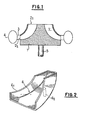
- the wheels of centrifugal compressors are generally formed by a rotor 1 defined by vanes 2, one of the ends 2 1 of which opens onto the front face called the "intake" face, the other end 2 2 communicating with a fixed diffuser 3 itself in relation to a peripheral volute 4.
- the fluid entering the channel delimited by the blades acquires pressure and speed there, this speed being convertible into pressure in the diffuser.
- the rotor is obviously rotated by a control shaft 5 to which it is coupled, several wheels can be stepped on the same shaft.
- the wheel is made from buckets 6 (Fig. 2) having the particularity of being made of fibers having a high mechanical resistance to rupture, each bucket being in the form of a sector to define in itself a channel.
- the wheel is of modular type, since it consists of a series of buckets 6 juxtaposed in a circumferential direction and made integral with one another, to form a stable unitary assembly, by bundles of radiating wires 9 coated with a liaison officer.
- the fibers used for making the buckets are preferably carbon fibers, although boron fibers, aromatic polyamides or even glass fibers can also be used. These fibers indeed make it possible to envisage, because of their high mechanical strength, high specific speeds, but it is however necessary, given the unidirectional nature of the fiber, to use specific morphologies so that the centrifugal forces are transmitted in the direction of the fiber and not perpendicular to them.
- Figs. 3 and 4 show the method of manufacturing a wheel according to the invention. It suffices to place in a star, on a marble 7 the troughs in the shape of a sector, taking care to leave between their lateral flanks 6 1 radial interstices 8,1 placement of the troughs being facilitated by stabilizing pins 6 2 are provided and which come to rest in the heel manner on the flat marble 7. Next, the buckets are coupled and sealed together by a stack of beams of radiating wires 9 previously coated with a bonding agent whose chemical nature is compatible with the material constituting the buckets and that constituting the wires, for example, an epoxy-type resin, if the buckets and the bundles of wires are based on carbon fibers.
- a bonding agent whose chemical nature is compatible with the material constituting the buckets and that constituting the wires, for example, an epoxy-type resin, if the buckets and the bundles of wires are based on carbon fibers.
- each radial gap 8 opens onto rods 11, integral with the marble and on which the connecting wires are wound.
- This carbon fiber wheel can be coupled either to a metal axle, or to an axle also made of carbon fibers.
- a metal axle or to an axle also made of carbon fibers.
- axial channels obtained by pins 12 passing right through the wheel and which, when they are removed from the mold, form passages in which the fingers 13 forming the end of the drive shaft 14 will be introduced.
- These fingers will be made integral with the wheel by a support plate 15 and bolts 16 fixed on the end of each of said fingers 13.
- the drive shaft is made of carbon fibers, it will include, like the metal shaft, fingers 13, as illustrated in Fig. 5, but these will be positioned, inserted and sealed to the wheel, as the bundles of wires are stacked. It will suffice, in this case, that the plate 7 has a central opening for the passage of the shaft and that the fingers 13 are arranged between the axis 10 of the wheel and the ends of the buckets (as illustrated by the reference 12 in Fig. 3) so that the shaft is coupled to the wheel by coating the wires like the buckets. After cooling and removing the marble 7, the wheel and the drive shaft will form a unitary and homogeneous whole.
- a cooking operation is then carried out in an oven, the temperature of which is defined by the type of resin used.
- the buckets can be covered with a continuous tulip-shaped veil also produced from carbon fibers bonded leaving; of course free, the inlet openings of the buckets opening onto the front face of the wheel, the opposite end of said buckets communicating in known manner with a rotor diffuser having the general shape of an annular crown.
Landscapes
- Engineering & Computer Science (AREA)
- Mechanical Engineering (AREA)
- General Engineering & Computer Science (AREA)
- Structures Of Non-Positive Displacement Pumps (AREA)
- Turbine Rotor Nozzle Sealing (AREA)
Priority Applications (1)
| Application Number | Priority Date | Filing Date | Title |
|---|---|---|---|
| AT84400027T ATE23211T1 (de) | 1983-01-26 | 1984-01-06 | Laufrad eines zentrifugalverdichters und verfahren zu seiner herstellung. |
Applications Claiming Priority (2)
| Application Number | Priority Date | Filing Date | Title |
|---|---|---|---|
| FR8301162 | 1983-01-26 | ||
| FR8301162A FR2539824A1 (fr) | 1983-01-26 | 1983-01-26 | Roue pour compresseur centrifuge et procede pour sa fabrication |
Publications (3)
| Publication Number | Publication Date |
|---|---|
| EP0115451A2 true EP0115451A2 (de) | 1984-08-08 |
| EP0115451A3 EP0115451A3 (en) | 1984-08-22 |
| EP0115451B1 EP0115451B1 (de) | 1986-10-29 |
Family
ID=9285297
Family Applications (1)
| Application Number | Title | Priority Date | Filing Date |
|---|---|---|---|
| EP84400027A Expired EP0115451B1 (de) | 1983-01-26 | 1984-01-06 | Laufrad eines Zentrifugalverdichters und Verfahren zu seiner Herstellung |
Country Status (10)
| Country | Link |
|---|---|
| US (1) | US4676722A (de) |
| EP (1) | EP0115451B1 (de) |
| JP (1) | JPS59150997A (de) |
| KR (1) | KR840007267A (de) |
| AT (1) | ATE23211T1 (de) |
| BR (1) | BR8400282A (de) |
| DE (1) | DE3461115D1 (de) |
| ES (1) | ES8500395A1 (de) |
| FR (1) | FR2539824A1 (de) |
| IN (1) | IN159386B (de) |
Cited By (3)
| Publication number | Priority date | Publication date | Assignee | Title |
|---|---|---|---|---|
| EP0635643A3 (de) * | 1993-06-25 | 1995-03-08 | Inst Luft Kaeltetech Gem Gmbh | Kältemittel-Turboverdichter. |
| EP0737814A1 (de) * | 1995-04-10 | 1996-10-16 | Abb Research Ltd. | Verdichter |
| DE10063653A1 (de) * | 2000-12-20 | 2002-07-11 | Daimler Chrysler Ag | Ladepumpe, insbesondere Abgasturbolader |
Families Citing this family (22)
| Publication number | Priority date | Publication date | Assignee | Title |
|---|---|---|---|---|
| GB2207629B (en) * | 1987-07-22 | 1991-01-02 | Rolls Royce Plc | Method of manufacture of an axial flow compressor assembly |
| JPH0631633B2 (ja) * | 1987-08-12 | 1994-04-27 | 株式会社ユニシアジェックス | タ−ビン型燃料ポンプ |
| US5222866A (en) * | 1988-09-30 | 1993-06-29 | Societe Europeenne De Propulsion | High speed composite turbine wheel |
| JPH04211232A (ja) * | 1990-03-14 | 1992-08-03 | Nikon Corp | 遮光羽根用またはアーム用板材 |
| DE19525829A1 (de) * | 1995-07-15 | 1997-01-16 | Abb Research Ltd | Lüfter |
| US5921754A (en) * | 1996-08-26 | 1999-07-13 | Foster-Miller, Inc. | Composite turbine rotor |
| FI101564B (fi) | 1997-01-17 | 1998-07-15 | Flaekt Woods Ab | Korkeapainepuhallin |
| FI101565B (fi) * | 1997-01-17 | 1998-07-15 | Flaekt Woods Ab | Haihdutinpuhallin ja sen siipipyörä |
| DE19708825C2 (de) * | 1997-03-05 | 2001-11-15 | Deutsch Zentr Luft & Raumfahrt | Vorrichtung zum Fördern eines Mediums |
| US6659723B2 (en) * | 2001-11-16 | 2003-12-09 | Illinois Tool Works Inc. | Fan for an engine driven generator |
| JP2004285938A (ja) * | 2003-03-24 | 2004-10-14 | Matsushita Electric Ind Co Ltd | 送風ファン |
| WO2007013892A2 (en) * | 2004-11-12 | 2007-02-01 | Board Of Trustees Of Michigan State University | Composite turbomachine impeller and method of manufacture |
| IT1394295B1 (it) | 2009-05-08 | 2012-06-06 | Nuovo Pignone Spa | Girante centrifuga del tipo chiuso per turbomacchine, componente per tale girante, turbomacchina provvista di tale girante e metodo di realizzazione di tale girante |
| IT1397058B1 (it) | 2009-11-23 | 2012-12-28 | Nuovo Pignone Spa | Stampo per girante centrifuga, inserti per stampo e metodo per costruire una girante centrifuga |
| IT1397057B1 (it) * | 2009-11-23 | 2012-12-28 | Nuovo Pignone Spa | Girante centrifuga e turbomacchina |
| US8794914B2 (en) | 2010-11-23 | 2014-08-05 | GM Global Technology Operations LLC | Composite centrifugal compressor wheel |
| ITCO20110064A1 (it) | 2011-12-14 | 2013-06-15 | Nuovo Pignone Spa | Macchina rotante comprendente un rotore con una girante composita ed un albero metallico |
| US10193430B2 (en) | 2013-03-15 | 2019-01-29 | Board Of Trustees Of Michigan State University | Electromagnetic device having discrete wires |
| ITCO20130067A1 (it) | 2013-12-17 | 2015-06-18 | Nuovo Pignone Srl | Girante con elementi di protezione e compressore centrifugo |
| KR102004977B1 (ko) * | 2019-04-04 | 2019-07-30 | (주)웰크론 | 공기 부양선용 임펠러 제조방법 |
| DE102020127312A1 (de) * | 2020-10-16 | 2022-04-21 | Ebm-Papst Mulfingen Gmbh & Co. Kg | Lüfter mit einem Rotor und einem Lüfterrad |
| US12576601B2 (en) * | 2024-01-30 | 2026-03-17 | General Electric Company | Composite structure for a turbine engine |
Family Cites Families (10)
| Publication number | Priority date | Publication date | Assignee | Title |
|---|---|---|---|---|
| US2857094A (en) * | 1955-07-19 | 1958-10-21 | John R Erwin | Integral plastic rotors |
| US3077297A (en) * | 1960-10-24 | 1963-02-12 | Stalker Corp | Bladed rotors |
| GB1170593A (en) * | 1967-04-12 | 1969-11-12 | Rolls Royce | Method of making a Bladed Rotor |
| US3518221A (en) * | 1967-10-30 | 1970-06-30 | Monsanto Co | Reinforcing fillers in a matrix of two thermosetting resins |
| US3521973A (en) * | 1968-08-16 | 1970-07-28 | Anpol Research Corp | Fan construction |
| US4098559A (en) * | 1976-07-26 | 1978-07-04 | United Technologies Corporation | Paired blade assembly |
| JPS5458211A (en) * | 1977-10-18 | 1979-05-10 | Koken Kogyo Kk | Preparation of impeller of turbo type fan |
| DE2800723C2 (de) * | 1978-01-09 | 1986-03-20 | Johnston Brothers (Engineering) Ltd., Redhill | Laufrad für Gebläse |
| DE2937214A1 (de) * | 1979-09-14 | 1981-04-02 | Rhein-Bayern Fahrzeugbau GmbH & Co KG, 8950 Kaufbeuren | Dreiflaechenstroemungsmaschine |
| US4465434A (en) * | 1982-04-29 | 1984-08-14 | Williams International Corporation | Composite turbine wheel |
-
1983
- 1983-01-26 FR FR8301162A patent/FR2539824A1/fr active Granted
-
1984
- 1984-01-06 EP EP84400027A patent/EP0115451B1/de not_active Expired
- 1984-01-06 AT AT84400027T patent/ATE23211T1/de not_active IP Right Cessation
- 1984-01-06 DE DE8484400027T patent/DE3461115D1/de not_active Expired
- 1984-01-11 US US06/569,955 patent/US4676722A/en not_active Expired - Fee Related
- 1984-01-14 KR KR1019840000139A patent/KR840007267A/ko not_active Withdrawn
- 1984-01-24 BR BR8400282A patent/BR8400282A/pt not_active IP Right Cessation
- 1984-01-25 IN IN53/CAL/84A patent/IN159386B/en unknown
- 1984-01-26 JP JP59013213A patent/JPS59150997A/ja active Pending
- 1984-01-26 ES ES529200A patent/ES8500395A1/es not_active Expired
Cited By (4)
| Publication number | Priority date | Publication date | Assignee | Title |
|---|---|---|---|---|
| EP0635643A3 (de) * | 1993-06-25 | 1995-03-08 | Inst Luft Kaeltetech Gem Gmbh | Kältemittel-Turboverdichter. |
| EP0737814A1 (de) * | 1995-04-10 | 1996-10-16 | Abb Research Ltd. | Verdichter |
| DE10063653A1 (de) * | 2000-12-20 | 2002-07-11 | Daimler Chrysler Ag | Ladepumpe, insbesondere Abgasturbolader |
| DE10063653C2 (de) * | 2000-12-20 | 2002-12-12 | Daimler Chrysler Ag | Ladepumpe, insbesondere Abgasturbolader |
Also Published As
| Publication number | Publication date |
|---|---|
| ES529200A0 (es) | 1984-10-01 |
| JPS59150997A (ja) | 1984-08-29 |
| EP0115451B1 (de) | 1986-10-29 |
| FR2539824A1 (fr) | 1984-07-27 |
| BR8400282A (pt) | 1984-08-28 |
| US4676722A (en) | 1987-06-30 |
| ES8500395A1 (es) | 1984-10-01 |
| KR840007267A (ko) | 1984-12-06 |
| DE3461115D1 (en) | 1986-12-04 |
| FR2539824B1 (de) | 1985-05-10 |
| EP0115451A3 (en) | 1984-08-22 |
| ATE23211T1 (de) | 1986-11-15 |
| IN159386B (de) | 1987-05-09 |
Similar Documents
| Publication | Publication Date | Title |
|---|---|---|
| EP0115451B1 (de) | Laufrad eines Zentrifugalverdichters und Verfahren zu seiner Herstellung | |
| FR2700130A1 (fr) | Procédé de fabrication d'un rotor monobloc à aubes creuses et rotor monobloc à aubes creuses. | |
| WO1999046511A1 (fr) | Roue de ventilation centrifuge en materiaux composites | |
| EP0330562B1 (de) | Drehende Ankern der elektromagnetischen Verzögerer | |
| EP1481756B1 (de) | Verfahren zur Herstellung einer hohlen Turbinenschaufel | |
| FR2567052A1 (fr) | Elements a aubes d'une seule piece | |
| CA1199669A (fr) | Rotor a jante feuilletee segmentee et poles rapportes pour machine electrique | |
| EP2811121B1 (de) | Verbundgehäuse für einen Kompressor einer axialen Turbomaschine mit Metallbefestigungsflansch | |
| FR2931719A1 (fr) | Procede de remplacement d'un profil composite. | |
| EP1859897B1 (de) | Verfahren zur Herstellung einer Gasturbinenrotorscheibe | |
| EP0618996B1 (de) | Verfahren zur herstellung eines turbinenrads mit axialeingefugten schaufeln und turbinenrad nach diesem verfahren | |
| FR2963055A1 (fr) | Aube de rotor d'un turbomoteur a gaz en materiau composite comprenant une chape de liaison, procede de fabrication de l'aube | |
| FR2863321A1 (fr) | Pale d'aerogenerateur integrant des moyens de liaison ameliores entre la racine de la pale et le moyeu de l'aerogenerateur, bride, procede de fabrication et aerogenerateur correspondant | |
| FR2650344A1 (fr) | Dispositif de compensation de balourd sur un rotor de compresseur centrifuge radial | |
| EP0153221B1 (de) | Herstellungsverfahren eines geschlossenen Flügelrades | |
| EP0538088B1 (de) | Mehrblätterrotor, insbesondere eines Hubschrauberdrehmomentausgleichsheckrotor, und sein Herstellungsverfahren | |
| EP2297838B1 (de) | Laüfer einer synchronen elektrischen mehrpolarmaschine mit schenkelpolen | |
| EP4189811A1 (de) | Rotor mit verbundstruktur | |
| EP2287445A1 (de) | Rotortrommel eines Axialkompressors mit Verbundgewebe | |
| FR2855440A1 (fr) | Procede de fabrication d'une aube creuse pour turbomachine. | |
| FR2499326A1 (fr) | Rotor d'une machine electrique a grande vitesse | |
| FR2641324A1 (fr) | Fixation de pied d'ailette pour une ailette de rotor en technique de fibre | |
| FR2631083A1 (fr) | Roue composite pour compresseur centrifuge et procede pour sa fabrication | |
| EP0775754B1 (de) | Verfahren zur Herstellung eines Metallmatrixverbundrotors | |
| CA2220987C (fr) | Etage de rotor de turbomachine renforce par des fibres |
Legal Events
| Date | Code | Title | Description |
|---|---|---|---|
| PUAI | Public reference made under article 153(3) epc to a published international application that has entered the european phase |
Free format text: ORIGINAL CODE: 0009012 |
|
| PUAL | Search report despatched |
Free format text: ORIGINAL CODE: 0009013 |
|
| AK | Designated contracting states |
Designated state(s): AT BE CH DE GB IT LI NL SE |
|
| AK | Designated contracting states |
Designated state(s): AT BE CH DE GB IT LI NL SE |
|
| 17P | Request for examination filed |
Effective date: 19841001 |
|
| 18W | Application withdrawn |
Withdrawal date: 19860415 |
|
| D18W | Application withdrawn (deleted) | ||
| GRAA | (expected) grant |
Free format text: ORIGINAL CODE: 0009210 |
|
| ITF | It: translation for a ep patent filed | ||
| AK | Designated contracting states |
Kind code of ref document: B1 Designated state(s): AT BE CH DE GB IT LI NL SE |
|
| REF | Corresponds to: |
Ref document number: 23211 Country of ref document: AT Date of ref document: 19861115 Kind code of ref document: T |
|
| REF | Corresponds to: |
Ref document number: 3461115 Country of ref document: DE Date of ref document: 19861204 |
|
| PLBE | No opposition filed within time limit |
Free format text: ORIGINAL CODE: 0009261 |
|
| STAA | Information on the status of an ep patent application or granted ep patent |
Free format text: STATUS: NO OPPOSITION FILED WITHIN TIME LIMIT |
|
| 26N | No opposition filed | ||
| PGFP | Annual fee paid to national office [announced via postgrant information from national office to epo] |
Ref country code: CH Payment date: 19921221 Year of fee payment: 10 |
|
| PGFP | Annual fee paid to national office [announced via postgrant information from national office to epo] |
Ref country code: GB Payment date: 19921222 Year of fee payment: 10 |
|
| PGFP | Annual fee paid to national office [announced via postgrant information from national office to epo] |
Ref country code: SE Payment date: 19921223 Year of fee payment: 10 |
|
| PGFP | Annual fee paid to national office [announced via postgrant information from national office to epo] |
Ref country code: BE Payment date: 19921230 Year of fee payment: 10 |
|
| PGFP | Annual fee paid to national office [announced via postgrant information from national office to epo] |
Ref country code: DE Payment date: 19930108 Year of fee payment: 10 |
|
| PGFP | Annual fee paid to national office [announced via postgrant information from national office to epo] |
Ref country code: AT Payment date: 19930127 Year of fee payment: 10 |
|
| ITTA | It: last paid annual fee | ||
| PGFP | Annual fee paid to national office [announced via postgrant information from national office to epo] |
Ref country code: NL Payment date: 19930131 Year of fee payment: 10 |
|
| PG25 | Lapsed in a contracting state [announced via postgrant information from national office to epo] |
Ref country code: GB Effective date: 19940106 Ref country code: AT Effective date: 19940106 |
|
| PG25 | Lapsed in a contracting state [announced via postgrant information from national office to epo] |
Ref country code: SE Effective date: 19940107 |
|
| PG25 | Lapsed in a contracting state [announced via postgrant information from national office to epo] |
Ref country code: LI Effective date: 19940131 Ref country code: CH Effective date: 19940131 Ref country code: BE Effective date: 19940131 |
|
| BERE | Be: lapsed |
Owner name: ARAP - APPLICATIONS RATIONNELLES DE LA PHYSIQUE S Effective date: 19940131 |
|
| PG25 | Lapsed in a contracting state [announced via postgrant information from national office to epo] |
Ref country code: NL Effective date: 19940801 |
|
| GBPC | Gb: european patent ceased through non-payment of renewal fee |
Effective date: 19940106 |
|
| NLV4 | Nl: lapsed or anulled due to non-payment of the annual fee | ||
| REG | Reference to a national code |
Ref country code: CH Ref legal event code: PL |
|
| PG25 | Lapsed in a contracting state [announced via postgrant information from national office to epo] |
Ref country code: DE Effective date: 19941001 |
|
| EUG | Se: european patent has lapsed |
Ref document number: 84400027.3 Effective date: 19940810 |