EP0115720A1 - Elektronenkanone für Linearbeschleuniger und Beschleunigungsstruktur mit derartiger Kanone - Google Patents
Elektronenkanone für Linearbeschleuniger und Beschleunigungsstruktur mit derartiger Kanone Download PDFInfo
- Publication number
- EP0115720A1 EP0115720A1 EP83402408A EP83402408A EP0115720A1 EP 0115720 A1 EP0115720 A1 EP 0115720A1 EP 83402408 A EP83402408 A EP 83402408A EP 83402408 A EP83402408 A EP 83402408A EP 0115720 A1 EP0115720 A1 EP 0115720A1
- Authority
- EP
- European Patent Office
- Prior art keywords
- grid
- cavity
- electron gun
- electromagnetic wave
- resonant cavity
- Prior art date
- Legal status (The legal status is an assumption and is not a legal conclusion. Google has not performed a legal analysis and makes no representation as to the accuracy of the status listed.)
- Granted
Links
- 230000008878 coupling Effects 0.000 claims description 11
- 238000010168 coupling process Methods 0.000 claims description 11
- 238000005859 coupling reaction Methods 0.000 claims description 11
- 230000005540 biological transmission Effects 0.000 claims description 8
- 239000002184 metal Substances 0.000 description 9
- 238000002347 injection Methods 0.000 description 5
- 239000007924 injection Substances 0.000 description 5
- 238000007789 sealing Methods 0.000 description 5
- 238000010894 electron beam technology Methods 0.000 description 4
- 230000007423 decrease Effects 0.000 description 2
- 230000002349 favourable effect Effects 0.000 description 2
- WNEODWDFDXWOLU-QHCPKHFHSA-N 3-[3-(hydroxymethyl)-4-[1-methyl-5-[[5-[(2s)-2-methyl-4-(oxetan-3-yl)piperazin-1-yl]pyridin-2-yl]amino]-6-oxopyridin-3-yl]pyridin-2-yl]-7,7-dimethyl-1,2,6,8-tetrahydrocyclopenta[3,4]pyrrolo[3,5-b]pyrazin-4-one Chemical compound C([C@@H](N(CC1)C=2C=NC(NC=3C(N(C)C=C(C=3)C=3C(=C(N4C(C5=CC=6CC(C)(C)CC=6N5CC4)=O)N=CC=3)CO)=O)=CC=2)C)N1C1COC1 WNEODWDFDXWOLU-QHCPKHFHSA-N 0.000 description 1
- 230000001133 acceleration Effects 0.000 description 1
- 239000000919 ceramic Substances 0.000 description 1
- 238000001816 cooling Methods 0.000 description 1
- 230000005684 electric field Effects 0.000 description 1
- 238000010292 electrical insulation Methods 0.000 description 1
- 238000010438 heat treatment Methods 0.000 description 1
- 238000009434 installation Methods 0.000 description 1
- 230000003071 parasitic effect Effects 0.000 description 1
- 230000010287 polarization Effects 0.000 description 1
- 230000003252 repetitive effect Effects 0.000 description 1
- 230000001954 sterilising effect Effects 0.000 description 1
- 238000004659 sterilization and disinfection Methods 0.000 description 1
- 230000001225 therapeutic effect Effects 0.000 description 1
- 238000011282 treatment Methods 0.000 description 1
- 238000003466 welding Methods 0.000 description 1
Images

Classifications
-
- H—ELECTRICITY
- H05—ELECTRIC TECHNIQUES NOT OTHERWISE PROVIDED FOR
- H05H—PLASMA TECHNIQUE; PRODUCTION OF ACCELERATED ELECTRICALLY-CHARGED PARTICLES OR OF NEUTRONS; PRODUCTION OR ACCELERATION OF NEUTRAL MOLECULAR OR ATOMIC BEAMS
- H05H7/00—Details of devices of the types covered by groups H05H9/00, H05H11/00, H05H13/00
- H05H7/14—Vacuum chambers
- H05H7/18—Cavities; Resonators
-
- H—ELECTRICITY
- H05—ELECTRIC TECHNIQUES NOT OTHERWISE PROVIDED FOR
- H05H—PLASMA TECHNIQUE; PRODUCTION OF ACCELERATED ELECTRICALLY-CHARGED PARTICLES OR OF NEUTRONS; PRODUCTION OR ACCELERATION OF NEUTRAL MOLECULAR OR ATOMIC BEAMS
- H05H9/00—Linear accelerators
Definitions
- the invention relates to an electron gun for a linear accelerator, allowing modulation of the electronic current as soon as this current is formed; it also relates to an accelerating structure provided with such an electron gun.
- Electron cannons of the triode type are used to generate electrons injected into an accelerating structure of a linear accelerator; an electromagnetic wave of frequency appropriate to the accelerating structure, makes it possible to accelerate these electrons and to produce a beam whose characteristics vary according to its application.
- These industrial irradiation machines allow for example the sterilization of various products, and can generally produce electron beams having energies between 1 and 10 MeV.
- pre-grouping cavities located on the path of the electrons; these pre-grouping cavities being commonly arranged between the electron gun and the accelerating structure into which these packets are injected.
- the electronic current supplied by the gun is established continuously, during a given and repetitive operating time; the electrons constituting this current are grouped by these cavities, in packets having a duration and a period determined by the operating characteristics of these pre-grouping cavities.
- Such grouping in packets of electrons can make it possible to improve the efficiency of a linear accelerator, insofar as it avoids consuming the energy conveyed by the electromagnetic wave, for electrons located outside the domain of ac - accelerator phase timing; but the implementation of these pre-grouping cavities is delicate and complex.
- an improvement in the overall efficiency of a machine using an accelerating structure is obtained by means of a modulation of the electronic current, produced from the generation of the latter by the electron gun; this modulation making it possible, for example, to obtain packets of electrons injected into the accelerating structure, without requiring pre-grouping cavities for this purpose.
- Electron guns for linear accelerator are frequently constituted by a thermoemissive cathode and an anode, between which a grid controls the electronic current according to a potential difference established between the grid and the cathode; this potential difference can be continuous to determine an operating time, as it was previously explained, or include within this operating time variations at high frequencies or brief transients. In the latter case, it constitutes a signal, generally produced by a complex injection modulator, transported by a transmission line having appropriate characteristics; but the establishment of this signal between the grid and the cathode, in respect with the signal produced by the injection modulator, presents difficulties due in particular to parasitic capacities.
- the present invention relates to an electron gun for a linear accelerator, capable of producing a modulated electronic current; its arrangement avoids the use of a complex injection modulator, and facilitates the establishment of an alternative potential difference between the grid and the cathode. It also relates to an accelerating structure of a linear electron accelerator, provided with a gun according to the invention, making it possible to improve the overall efficiency of a machine using such an accelerating structure.
- an electron gun for linear accelerator comprising a cathode capable of generating an electronic current, a grid capable of controlling this current, an anode pierced with a hole centered around an axis along which the electrons are emitted.
- a cathode capable of generating an electronic current
- a grid capable of controlling this current
- it further comprises a resonant cavity closed on a grid-cathode space, the resonant cavity containing an electromagnetic coupling member linked to a transmission line and making it possible to inject an electromagnetic wave of frequency F into this resonant cavity, in order to bring the latter into resonance and to excite the grid-cathode space so as to determine between the grid and the cathode, an AC potential difference of frequency F by which the electronic current is modulated.
- the electromagnetic wave used to modulate the electronic current generated by such an electron gun can be taken and injected into the resonant cavity of the gun either: from a generator specific to this function; either from a generator intended to supply an electromagnetic wave injected into an accelerating structure, or by taking the latter electromagnetic wave in an accelerating cavity of this structure, and in particular in an accelerating cavity closest to the gun.
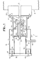
- FIG. 1 shows an electron gun 1 according to the invention.
- This gun 1 has an anode 2; in the nonlimiting example described, this is fixed by screws 4 to an element 50 of an accelerating structure 3, partially shown.
- a hole 5 intended for the passage of the electrons is centered on an axis 6 according to which the electrons, emitted by a cathode 8, are attracted by the anode 2.
- the cathode 8 comprises a filament 9 and the electrons attracted by the anode 2 pass through the plane of a grid 10 intended to control the passage of the electrons; the grid 10 is held by a metal support tube II, centered around the emission axis 6.
- This support tube 11 constitutes an extension of a cavity 13 of coaxial type, itself centered around the axis of show 6; the support tube 11 is fixed to a first transverse wall 12 of this cavity 13, for example by welding.
- the cavity 13 thus communicates with an additional space 18 delimited by the grid 10, the support tube 11, the internal metal tube 14, with which this cavity 13 constitutes a resonant cavity 13-18 coaxial.
- the resonant cavity 13-18 arranged along a longitudinal axis coincident with the emission axis 6, is thus limited at one end 7 by the grid 10; the cathode 8 being at a distance d from the grid which constitutes a cathode-grid space 8-10 on which, in operation, the resonant cavity 13-18 is closed.
- the cathode 8 is secured in a conventional manner to a plate 21, which comprises first and second pads P 1 , P 2 , to which the ends F 1 , F 2 of the filament 9 are respectively connected; the cathode 8 being for example also connected to the second stud P 2.
- the plate 21 of circular shape is embedded in the inner metal tube 14 and, it is supported by a central insulating pin 25; the latter is fixed to the internal transverse metal wall 26 of the cavity 13, in a conventional manner, by means (not shown) allowing, thanks to the sealing means 22, to maintain the vacuum.
- a first electrical connection 28 connects the first stud P 1 , to a sealed crossing 30, and a second electrical connection 29 located axially inside the central stud 25, connects the second stud P 2 to a second sealed crossing 31.
- These crossings watertight constitute connection means allowing the supply of the filament 9 and the electrical access to the cathode 8; in order to allow electrical insulation between the cathode 8 and the grid 10, the internal metal tube 14 comprises an insulating ring 60.
- the electrical supply both at high voltage and at low voltage of the electron gun 1, being carried out so conventional, the circuits intended for this operation as well as possible means for cooling the barrel 1 are not shown.
- a second insulating tube 33 placed in the extension of the first tube 20, making it possible to ensure a vacuum tightness thanks to the sealing means 22: this being achieved in order to avoid establishing a vacuum in the whole of the resonant cavity 13-18, which thus comprises a first part B subjected to the vacuum and a second part C at atmospheric pressure for example.
- This arrangement facilitates the installation of an adjustment piston 42 and a electromagnetic coupling means 50, which will be further explained in the following description.
- the cavity 13 is formed by a first and a second metal tube 35, 36 coaxial with the emission axis 6, and constituting respectively an outer wall and an inner wall of the cavity 13; the outer wall 35 being secured to the first transverse wall 12, and the inner wall 36 being secured to the second inner transverse wall 26.
- a rear end 37 of the cavity 13 has a bottom plate 38 serving in particular to hold the outer walls and interior 35.36.
- the cavity 13 also includes a metal ring 42 contained between the external and internal walls 35, 36, this ring being able to be moved parallel to the emission axis 6, thanks to the action of a screw 43 secured to the plate. background 38; this metal ring constitutes the adjustment means 42 already mentioned, making it possible to modify the dimensions of the resonant cavity 13-18, and to adjust in operation the resonant frequency of the latter.
- the rear end 37 of the resonant cavity 13-18- is thus closed by a short circuit; it should be noted that this piston 42 being in the part C not subjected to vacuum, it does not pose any problem with regard to sealing.
- the outer wall 35 has a passage 45 to which a transmission line 46 is applied; in the nonlimiting example described, this transmission line is a coaxial line, one end of which plunges into the cavity 13, and provided with an electromagnetic coupling means 50.
- this coupling means 50 is located in part C not subjected to the vacuum of the resonant cavity 13-18, which can facilitate the problems of connection of transmission line 46.
- Magnetic and electric fields (not shown) at frequency F then develop in a conventional manner in the resonant cavity 13-18, and excite the grid-cathode space 10-8; this determines a difference in alternating potential of frequency F between the gate 10 and the cathode 8.
- the electronic current delivered by the barrel 1 can thus be modulated more or less deeply, depending on the desired goal; the modulation depth or the type of modulation being obtained in particular, as a function of the level of polarization between the grid 10 and the cathode 8, of the level of the electromagnetic wave injected into the resonant cavity 13-18, and also as a function of the distance d between the grid 10 and the cathode 8.
- the cavity 13 possibly having a different shape, as well as the coupling member 50; the latter can also be constituted by a coupling loop (not shown) rather than by a capacitive coupling as shown in FIG. 1.
- the coupling member 50 can also be constituted by a coupling loop (not shown) rather than by a capacitive coupling as shown in FIG. 1.
- a person skilled in the art can imagine a different structure for supporting the cathode 8, the wafer 21, and feed the filament 9.
- an electromagnetic wave of frequency F suitable for an accelerating structure into which it is injected makes it possible to accelerate electrons; having passed through this structure, the electrons constitute a beam of accelerated electrons of given energy.
- An accelerator structure generally consists of a succession of n accelerator cavities; in order to use the example of an irradiator with industrial application cited in the preamble, these accelerating cavities can be as described in a patent application by the applicant, published under No. 2,477,827.
- FIG. 2 schematically shows by way of nonlimiting example, an accelerating structure 3, comprising such accelerating cavities C 1 , C 2 , C 3 ; a single accelerating cavity C 1 may also be sufficient in certain cases. Electrons supplied by the barrel 1 according to the invention are injected into the accelerating structure 3 in a conventional manner, by means of a sliding and focusing element 50.
- the electrons are accelerated in the accelerating structure 3 in a medium direction A, merged with the axis 6 of emission of the electrons generated by the gun 1, thanks to an electromagnetic wave OE of frequency F provided by a generator 51.
- This wave is injected into the accelerating structure 3, in the accelerating cavity C 2 for example, by means of conventional coupling means, not shown, as well as coupling means between the resonant cavities C 1 , C 2 ′ C 3 .
- the electromagnetic wave OE at frequency F is also injected into the barrel 1, via a transformer device 52 and an adjustable phase shifter device 53.
- This makes it possible to inject into the barrel 1, the electromagnetic wave OE of frequency F generated by the generator 51, with an adjustable phase relative to that of the wave injected into the cavity C 2 ; this arrangement making it possible to modulate the electronic current delivered by the barrel 1 at the same frequency F, as that injected into the accelerating structure 3 for the acceleration of the electrons.
- electrons injected into the first accelerating cavity CI acquire therein, if the phase of the electromagnetic wave OE is favorable to them, a speed close to that of light.
- the time during which the energy conveyed by this wave is given up to the electrons is at most equal to a half-period of this wave.
- a length L to be traversed by these in each cavity C 1 , C 2 , C 3 is less than half a wavelength; a sliding space 61 located between each cavity allowing the electrons to recover a correct phase of the wave, when they enter a next cavity.
- Such an arrangement is applicable to any linear accelerating structure of electrons. It enables the energy consumed in the electromagnetic wave to be reduced, while improving the energy homogeneity of an accelerated electron beam thus obtained.
Landscapes
- Physics & Mathematics (AREA)
- Engineering & Computer Science (AREA)
- Plasma & Fusion (AREA)
- Spectroscopy & Molecular Physics (AREA)
- Particle Accelerators (AREA)
- Electron Sources, Ion Sources (AREA)
Applications Claiming Priority (2)
| Application Number | Priority Date | Filing Date | Title |
|---|---|---|---|
| FR8221399A FR2538206B1 (fr) | 1982-12-21 | 1982-12-21 | Canon a electrons pour accelerateur lineaire et structure acceleratrice comportant un tel canon |
| FR8221399 | 1982-12-21 |
Publications (2)
| Publication Number | Publication Date |
|---|---|
| EP0115720A1 true EP0115720A1 (de) | 1984-08-15 |
| EP0115720B1 EP0115720B1 (de) | 1987-03-11 |
Family
ID=9280324
Family Applications (1)
| Application Number | Title | Priority Date | Filing Date |
|---|---|---|---|
| EP83402408A Expired EP0115720B1 (de) | 1982-12-21 | 1983-12-13 | Elektronenkanone für Linearbeschleuniger und Beschleunigungsstruktur mit derartiger Kanone |
Country Status (5)
| Country | Link |
|---|---|
| US (1) | US4617494A (de) |
| EP (1) | EP0115720B1 (de) |
| CA (1) | CA1214874A (de) |
| DE (1) | DE3370235D1 (de) |
| FR (1) | FR2538206B1 (de) |
Cited By (4)
| Publication number | Priority date | Publication date | Assignee | Title |
|---|---|---|---|---|
| FR2582180A1 (fr) * | 1985-05-20 | 1986-11-21 | Us Energy | Accelerateur d'electrons pulse optiquement |
| EP0420671A3 (en) * | 1989-09-29 | 1991-12-11 | Kabushiki Kaisha Toshiba | Synchrotron radiation apparatus |
| FR2694447A1 (fr) * | 1990-06-15 | 1994-02-04 | Thomson Csf | Canon à électrons pour fournir des électrons groupés en impulsions courtes. |
| US5342811A (en) * | 1988-05-26 | 1994-08-30 | The Dow Chemical Company | Composition and method for producing boron carbide/titanium diboride composite ceramic powders using a boron carbide substrate |
Families Citing this family (6)
| Publication number | Priority date | Publication date | Assignee | Title |
|---|---|---|---|---|
| US4641103A (en) * | 1984-07-19 | 1987-02-03 | John M. J. Madey | Microwave electron gun |
| US5233269A (en) * | 1990-04-13 | 1993-08-03 | Varian Associates, Inc. | Vacuum tube with an electron beam that is current and velocity-modulated |
| US5401973A (en) * | 1992-12-04 | 1995-03-28 | Atomic Energy Of Canada Limited | Industrial material processing electron linear accelerator |
| US6118847A (en) * | 1998-01-15 | 2000-09-12 | Siemens Medical Systems, Inc. | System and method for gated radiotherapy based on physiological inputs |
| US20120229024A1 (en) * | 2011-03-10 | 2012-09-13 | Elekta Ab (Publ) | Electron source for linear accelerators |
| CN119729989B (zh) * | 2024-12-19 | 2025-10-10 | 合肥综合性国家科学中心能源研究院(安徽省能源实验室) | 一种2.5mv硅整流堆高压平台的加速器离子源供电传输系统 |
Citations (4)
| Publication number | Priority date | Publication date | Assignee | Title |
|---|---|---|---|---|
| GB815063A (en) * | 1955-02-17 | 1959-06-17 | Vickers Electrical Co Ltd | Improvements relating to linear electron accelerators |
| US3769599A (en) * | 1970-04-28 | 1973-10-30 | Thomson Csf | Particle preaccelerator arrangement |
| FR2389992A1 (en) * | 1977-05-05 | 1978-12-01 | Cgr Mev | CRT electron gun construction - has concentric, circular, annular and cylindrical plates defining vacuum envelope and active element electrodes |
| EP0035445A2 (de) * | 1980-03-04 | 1981-09-09 | C.G.R. MeV | Im Meterwellenbereich arbeitender Beschleuniger für geladene Teilchen |
Family Cites Families (5)
| Publication number | Priority date | Publication date | Assignee | Title |
|---|---|---|---|---|
| US2278210A (en) * | 1940-07-05 | 1942-03-31 | Bell Telephone Labor Inc | Electron discharge device |
| US2792520A (en) * | 1952-12-24 | 1957-05-14 | Gen Electric | Ultra-high frequency discharge device |
| US2857480A (en) * | 1953-03-27 | 1958-10-21 | Gen Electric | Space charge grid electron beam amplifier with dual outputs |
| US3061791A (en) * | 1956-11-23 | 1962-10-30 | Gen Precision Inc | Microwave detector |
| US4527091A (en) * | 1983-06-09 | 1985-07-02 | Varian Associates, Inc. | Density modulated electron beam tube with enhanced gain |
-
1982
- 1982-12-21 FR FR8221399A patent/FR2538206B1/fr not_active Expired
-
1983
- 1983-12-13 DE DE8383402408T patent/DE3370235D1/de not_active Expired
- 1983-12-13 EP EP83402408A patent/EP0115720B1/de not_active Expired
- 1983-12-16 US US06/562,442 patent/US4617494A/en not_active Expired - Fee Related
- 1983-12-20 CA CA000443833A patent/CA1214874A/en not_active Expired
Patent Citations (4)
| Publication number | Priority date | Publication date | Assignee | Title |
|---|---|---|---|---|
| GB815063A (en) * | 1955-02-17 | 1959-06-17 | Vickers Electrical Co Ltd | Improvements relating to linear electron accelerators |
| US3769599A (en) * | 1970-04-28 | 1973-10-30 | Thomson Csf | Particle preaccelerator arrangement |
| FR2389992A1 (en) * | 1977-05-05 | 1978-12-01 | Cgr Mev | CRT electron gun construction - has concentric, circular, annular and cylindrical plates defining vacuum envelope and active element electrodes |
| EP0035445A2 (de) * | 1980-03-04 | 1981-09-09 | C.G.R. MeV | Im Meterwellenbereich arbeitender Beschleuniger für geladene Teilchen |
Cited By (4)
| Publication number | Priority date | Publication date | Assignee | Title |
|---|---|---|---|---|
| FR2582180A1 (fr) * | 1985-05-20 | 1986-11-21 | Us Energy | Accelerateur d'electrons pulse optiquement |
| US5342811A (en) * | 1988-05-26 | 1994-08-30 | The Dow Chemical Company | Composition and method for producing boron carbide/titanium diboride composite ceramic powders using a boron carbide substrate |
| EP0420671A3 (en) * | 1989-09-29 | 1991-12-11 | Kabushiki Kaisha Toshiba | Synchrotron radiation apparatus |
| FR2694447A1 (fr) * | 1990-06-15 | 1994-02-04 | Thomson Csf | Canon à électrons pour fournir des électrons groupés en impulsions courtes. |
Also Published As
| Publication number | Publication date |
|---|---|
| DE3370235D1 (en) | 1987-04-16 |
| FR2538206A1 (fr) | 1984-06-22 |
| US4617494A (en) | 1986-10-14 |
| FR2538206B1 (fr) | 1985-06-07 |
| EP0115720B1 (de) | 1987-03-11 |
| CA1214874A (en) | 1986-12-02 |
Similar Documents
| Publication | Publication Date | Title |
|---|---|---|
| EP0115720B1 (de) | Elektronenkanone für Linearbeschleuniger und Beschleunigungsstruktur mit derartiger Kanone | |
| EP0013242B1 (de) | Generator für elektromagnetische Wellen sehr hoher Frequenz | |
| EP0238397B1 (de) | Elektronenzyklotronresonanz-Ionenquelle mit koaxialer Injektion elektromagnetischer Wellen | |
| EP0564359B1 (de) | Mikrowellenstrahler und Plasmareaktor unter Verwendung dieser Einrichtung | |
| EP0360655B1 (de) | Vorrichtung zur beidseitigen Bestrahlung eines Produktes | |
| CH623182A5 (de) | ||
| EP0496681A1 (de) | Vorrichtung zur Verteilung von Mikrowellenenergie zur Plasmaanregung | |
| FR2643506A1 (fr) | Dispositif generateur d'ondes hyperfrequences a cathode virtuelle | |
| EP0248689A1 (de) | Mehrstrahlklystron | |
| EP0711100A1 (de) | Plasmaerzeugungsvorrichtung, ermöglichend eine Trennung zwischen Mikrowellenübertragung und -absorptionszonen | |
| FR2642584A1 (fr) | Dispositif amplificateur ou oscillateur fonctionnant en hyperfrequence | |
| EP0035445B1 (de) | Im Meterwellenbereich arbeitender Beschleuniger für geladene Teilchen | |
| EP2472555B1 (de) | Vorrichtung zum Erzeugen von Mikrowellen, die eine Vielzahl von Magnetrons umfasst | |
| EP0184475A1 (de) | Verfahren und Vorrichtung zum Starten einer Mikrowellenionenquelle | |
| EP0049198B1 (de) | Elektronenbeschleuniger sowie Millimeter- und Submillimeterwellengenerator mit einem solchen Beschleuniger | |
| EP1982347A1 (de) | Einrichtung zur kopplung zwischen einer plasmaantenne und einem leistungssignalgenerator | |
| FR2672730A1 (fr) | Dispositif convertisseur de modes et diviseur de puissance pour tube hyperfrequence et tube hyperfrequence comprenant un tel dispositif. | |
| FR2694447A1 (fr) | Canon à électrons pour fournir des électrons groupés en impulsions courtes. | |
| FR2724264A1 (fr) | Antenne cylindrique utilisable pour generer un plasma dans les conditions de resonance cyclotronique electronique | |
| EP0415823A1 (de) | Frei-Elektronen-Laser | |
| JPH0539578A (ja) | プラズマ処理装置 | |
| FR2526582A1 (fr) | Procede et appareil pour produire des micro-ondes | |
| EP2339899B1 (de) | Kompakte Quelle zur Erzeugung von geladenen Teilchen | |
| EP0122186B1 (de) | Mikrowellenerzeuger | |
| EP0813223A1 (de) | Magnetfelderzeugungsvorrichtung und ECR Ionenquelle dafür |
Legal Events
| Date | Code | Title | Description |
|---|---|---|---|
| PUAI | Public reference made under article 153(3) epc to a published international application that has entered the european phase |
Free format text: ORIGINAL CODE: 0009012 |
|
| AK | Designated contracting states |
Designated state(s): CH DE GB LI NL |
|
| 17P | Request for examination filed |
Effective date: 19841108 |
|
| RBV | Designated contracting states (corrected) |
Designated state(s): CH DE GB LI |
|
| GRAA | (expected) grant |
Free format text: ORIGINAL CODE: 0009210 |
|
| AK | Designated contracting states |
Kind code of ref document: B1 Designated state(s): CH DE GB LI |
|
| REF | Corresponds to: |
Ref document number: 3370235 Country of ref document: DE Date of ref document: 19870416 |
|
| REG | Reference to a national code |
Ref country code: CH Ref legal event code: PFA Free format text: C.G.R. - MEV |
|
| PLBE | No opposition filed within time limit |
Free format text: ORIGINAL CODE: 0009261 |
|
| STAA | Information on the status of an ep patent application or granted ep patent |
Free format text: STATUS: NO OPPOSITION FILED WITHIN TIME LIMIT |
|
| 26N | No opposition filed | ||
| PGFP | Annual fee paid to national office [announced via postgrant information from national office to epo] |
Ref country code: GB Payment date: 19901203 Year of fee payment: 8 Ref country code: DE Payment date: 19901203 Year of fee payment: 8 |
|
| PGFP | Annual fee paid to national office [announced via postgrant information from national office to epo] |
Ref country code: CH Payment date: 19901231 Year of fee payment: 8 |
|
| PG25 | Lapsed in a contracting state [announced via postgrant information from national office to epo] |
Ref country code: GB Effective date: 19911213 |
|
| PG25 | Lapsed in a contracting state [announced via postgrant information from national office to epo] |
Ref country code: LI Effective date: 19911231 Ref country code: CH Effective date: 19911231 |
|
| GBPC | Gb: european patent ceased through non-payment of renewal fee | ||
| REG | Reference to a national code |
Ref country code: CH Ref legal event code: PL |
|
| PG25 | Lapsed in a contracting state [announced via postgrant information from national office to epo] |
Ref country code: DE Effective date: 19920901 |