EP0115760A2 - Platine d'impression thermique pour un dispositif d'impression thermique - Google Patents
Platine d'impression thermique pour un dispositif d'impression thermique Download PDFInfo
- Publication number
- EP0115760A2 EP0115760A2 EP84100005A EP84100005A EP0115760A2 EP 0115760 A2 EP0115760 A2 EP 0115760A2 EP 84100005 A EP84100005 A EP 84100005A EP 84100005 A EP84100005 A EP 84100005A EP 0115760 A2 EP0115760 A2 EP 0115760A2
- Authority
- EP
- European Patent Office
- Prior art keywords
- resistor
- thermal printing
- current
- resistors
- printing board
- Prior art date
- Legal status (The legal status is an assumption and is not a legal conclusion. Google has not performed a legal analysis and makes no representation as to the accuracy of the status listed.)
- Granted
Links
Images

Classifications
-
- B—PERFORMING OPERATIONS; TRANSPORTING
- B41—PRINTING; LINING MACHINES; TYPEWRITERS; STAMPS
- B41J—TYPEWRITERS; SELECTIVE PRINTING MECHANISMS, i.e. MECHANISMS PRINTING OTHERWISE THAN FROM A FORME; CORRECTION OF TYPOGRAPHICAL ERRORS
- B41J2/00—Typewriters or selective printing mechanisms characterised by the printing or marking process for which they are designed
- B41J2/315—Typewriters or selective printing mechanisms characterised by the printing or marking process for which they are designed characterised by selective application of heat to a heat sensitive printing or impression-transfer material
- B41J2/32—Typewriters or selective printing mechanisms characterised by the printing or marking process for which they are designed characterised by selective application of heat to a heat sensitive printing or impression-transfer material using thermal heads
- B41J2/35—Typewriters or selective printing mechanisms characterised by the printing or marking process for which they are designed characterised by selective application of heat to a heat sensitive printing or impression-transfer material using thermal heads providing current or voltage to the thermal head
-
- B—PERFORMING OPERATIONS; TRANSPORTING
- B41—PRINTING; LINING MACHINES; TYPEWRITERS; STAMPS
- B41J—TYPEWRITERS; SELECTIVE PRINTING MECHANISMS, i.e. MECHANISMS PRINTING OTHERWISE THAN FROM A FORME; CORRECTION OF TYPOGRAPHICAL ERRORS
- B41J2/00—Typewriters or selective printing mechanisms characterised by the printing or marking process for which they are designed
- B41J2/315—Typewriters or selective printing mechanisms characterised by the printing or marking process for which they are designed characterised by selective application of heat to a heat sensitive printing or impression-transfer material
- B41J2/32—Typewriters or selective printing mechanisms characterised by the printing or marking process for which they are designed characterised by selective application of heat to a heat sensitive printing or impression-transfer material using thermal heads
- B41J2/345—Typewriters or selective printing mechanisms characterised by the printing or marking process for which they are designed characterised by selective application of heat to a heat sensitive printing or impression-transfer material using thermal heads characterised by the arrangement of resistors or conductors
Definitions
- the invention relates to a thermal printing circuit board for a thermal printing device, consisting of an electrically insulating substrate on which resistors forming pressure points and current supply and discharge conductors contacting them are arranged.
- DE-AS 25 37 142 is a thin-film thermal print head with a substrate, a glass layer on the substrate, heating elements made of resistance material, several electrical conductors which are connected to the heating elements for supplying electrical power and a cover layer made of wear-resistant material with a Relatively high thermal conductivity has become known, in which gold or aluminum is used as the conductor material for producing the electrical conductor tracks for supplying and discharging the individual resistor pressure points. This material for the electrical conductor tracks is applied, for example, by vapor deposition or sputtering and contacted with the individual resistor.
- resistor is also known under the term "resistance element" or "heating element".
- the invention is therefore based on the object of creating a thermal printing board of the type mentioned at the beginning, in which the individual resistor is heated at least uniformly, but preferably is preferably heated in its upper region above the contact.
- thermoplate according to the invention has the advantage that the individual resistor pressure points have their highest temperature on the printing surface, ie exactly where the individual pressure point has to give off the heat to the recording medium. This results in the further advantage that the amount of heat that heats up the resistor is released to the recording medium more quickly and therefore the cooling time of the individual resistor printing point is reduced, which is why a higher printing speed can be achieved with the thermal printing board.
- the invention embraces the fact that current-carrying conductors experience mechanical forces in the homogeneous magnetic field, which force the two conductors outward in the case of an antiparallel current direction, the two conductors repel each other (Moeller, Fundamentals of Electrical Engineering 1963, 12th edition, page 133 .)
- the basic idea of the invention is therefore to push the current paths within the individual resistor or ⁇ the resistors by an external magnetic field in such a way that the current paths are pushed upward into the upper part of the resistors toward the surface.
- this can either be achieved by the magnetic field of a permanent magnet, the poles of which are arranged above and below the resistor printing line along the same and whose polarity is directed in such a way that the current paths are pushed upwards towards the surface when the current flows through the resistor.
- the magnetic field is generated by a current conductor arranged insulated below each resistor, which current also flows through when the current flows through the resistor, in which case the current through the current conductor must be antiparallel to the current through the resistor. So it always depends on the effect of the magnetic field.
- the current that is arranged below the resistor can be used to send the current in the antiparallel direction that is required to control the relevant resistor pressure point.
- the external magnetic field is directed in such a way that the magnetic field lines of this external magnetic field want to suppress the magnetic field lines of the current paths within the resistor, which means that the current paths within the resistor move upwards Surface of the same be pushed.
- thermoplate 1, for example, a thermoplate according to the invention consists of a substrate 1, on which a resistor layer is applied, which is subdivided into individual resistors 3 cubic. These resistors 3 thus have a conical or / shape.
- These thin gold layers are known to be vapor-deposited or printed on.
- each resistive pressure point 3 and below the insulating layer 2 there is a current conductor 6 in the longitudinal direction of the resistive pressure point, which is also preferably vapor-deposited or printed onto the substrate 1 in a known manner. Such a parallel current conductor is assigned to each resistor pressure point 3.
- the individual resistor pressure points are now controlled in accordance with the printing program.
- the underlying current paths 6 are driven in such a way that the electrical current through the current conductor 6 is directed antiparallel to the current direction in the associated resistor pressure point 3.
- the current paths 9 within the resistor 3 which otherwise were preferably formed in the lower part of the resistor pressure point 3 up to the level of the gold contact 4, 5, are now in the upper part 10 of the resistor pressure point 9 pushed away.
- the current paths that are pushed off are identified by puncturing.
- the current directions in the current supply and discharge lines, in the resistor pressure point and in the current conductor 6 are marked by the directional arrows 7 and 8, respectively.
- All current conductors 6, which are arranged below the resistor pressure points of a resistor layer, can in this case be constantly supplied with current antiparallel to the current direction within the individual resistor pressure points. To reduce energy consumption, however, it is advantageous to the individual
- the current conductor below the individual resistor pressure point is preferably a flat conductor, the width of this current conductor below the individual resistor point having the width of the resistor pressure point.
- the current conductor is advantageously arranged in the immediate vicinity below the individual resistor pressure point. The closer the current conductor can be brought to the underside of the resistor pressure point, the greater the upward displacement effect of the current paths within the resistor pressure point with a constant current through the current conductor below.
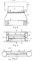
- FIG. 2 shows the schematic arrangement of a permanent magnet for generating the opposing magnetic field according to the basic alternative to the exemplary embodiment in FIG. 1.
- a permanent magnet which is for example a double L magnet or a horseshoe magnet 14, consists of a connecting part 21, on which two legs 22, 23 are formed, the ends of which are shaped as poles 15, 16.
- These poles 15, 16 face each other with their surfaces parallel to each other and have the length and width of the resistor printing line, the width of the poles 15, 16 with regard to the width of the individual resistor printing point 12 from FIG. 2 and with regard to the length of the resistor printing line 20 from FIG.
- a thermal printing plate 11 is arranged within the air gap, on which a resistor printing line 20 (FIG. 3) consisting of individual resistors 12 (FIGS. 2 and 3) is arranged.
- the upper pole 15 of the upper leg 22 of the permanent magnet 14 is thus located at some distance directly above the resistor print line 2 0, the lower pole 16 of the lower leg 23 of the permanent magnet 14 is located directly underneath the thermal print circuit board 11 in Projection also below the resistor print line 2 0 .
- the upper pole 15 of the permanent magnet 14 has a slight distance from the print line Resistor- 2 0, so that might happen to be printed on the paper web 13 between the upper pole 15 and the resistor print line 2o.
- the reference arrow 17 in FIG. 2 indicates, for example, the transport direction of the paper web.
- the thermal printing plate 11 is suitably held on a carrier 39, the carrier 39 in turn being held in the printing device (not shown).
- the carrier 39 is preferably pivotally arranged so that the resistor print line 20 in the direction of the upper pole 15 of the permanent magnet 14 and can be pivoted back, which is indicated by the reference arrow 42 in Figure 2.
- the thermal printing plate 11 can be pivoted in the direction of the upper pole 15, so that the paper web 13 is pressed between the thermal printing plate 11 and the upper pole 15.
- the pole 15 can have a support (not shown) made of elastic material which does not influence the continuity of the magnetic field lines 19, for example rubber.
- the permanent magnet 14 has a narrow window 24 through which the paper web 13 runs.
- the window 24 can lie in the same plane as the resistor print line 20, which is shown in FIG. 3; but the window may also be arranged rotated by 0 9 0, so that the paper web between the resistor print line 2o and the window 9 to 0 ° is twisted. In this way, the window only slightly affects the lines of force within the magnet. Likewise, the paper web can be guided past the connecting part when rotated through 90 ° after the resistor print line.
- Figures 4, 5 and 6 show a further embodiment of the invention with regard to the alternative of generating the displacing magnetic field by means of permanent magnets.
- a thermal printing board 27 is in turn suitably supported on a carrier (not shown) which in turn is arranged inside the printing device (not shown).
- the thermal printing board 27 carries, in a known manner (as in FIG. 3), a resistor printing line 36, which in turn consists of individual resistors. stands.
- two rod-shaped permanent magnets 28, 29 are arranged perpendicular to the main plane thereof, which are preferably cylindrical (FIG. 5).
- the poles 3 0 , 32 and 31, 33 of the two permanent magnets 28, 29 are connected to each other by means of a plate 34, 35 made of soft iron, so that the plates are aligned plane-parallel to one another.
- the plate 34 joins the north poles 3 0, 32 of the permanent magnets 28, 29, the plate 35 connects the south poles 31, 33 in the same manner.
- the plates 34, 35 each have a cutting-like elevation 37, 38 on the side facing the thermal printing plate 27, which are thus web-like. These webs 37, 38 the resistor print line extending along 36.
- the final section of the webs 37, 38 is in each case as a continuous pole or pole bus 4 0, configured 41 ( Figure 6), the respective pole bus 4 0, 41 of the web 37, 38 is arranged directly above the resistor print line 36.
- the web 38 of the plate 35 extends to the underside of the thermal printing plate 27, the web 37 or the pole rail 41 of the webs 37 is arranged at a small distance from the resistor printing line 36, so that a (not shown) paper web between the Pole rail 41 and the resistor print line 36 can pass through.
- the two Polschienen 4 0, 41 thus include an air gap along the resistor print line 36 a. Since the length of the permanent magnets 28, 29 is greater by a multiple than the vertical distance between the Polschienen 4 0, 41 from one another or when the thus formed air spal t run from the permanent magnets 28, 29 emerging field lines preferably within the plates 34, 35 made of soft iron, whereby within the air gap between the Polschienen 4 0, 41, two magnetic fields are established, the one associated with the permanent magnet 28, others belonging to the permanent magnet 29.
- the use of a permanent magnet to generate the deflecting magnetic field has the advantage that very strong magnetic fields can be generated here, whereby a strong deflection of the current lines within the individual resistor pressure points is achieved.
- the power required to energize the individual resistor pressure points can be further reduced, as a result of which the heat to be dissipated is reduced, which in turn increases the printing speed of the printer and thus the performance of the printer.
- both alternatives for generating the displacing magnetic field can be combined in an advantageous manner.
- the permanent magnet for generating the displacing magnetic field can be designed in such a way that it is horseshoe-shaped with two legs and poles according to FIG. 2, but the legs are bent at right angles in their plane or are cranked.
- the connecting part of the permanent magnet between the two legs is arranged on one of the narrow sides of the thermal printing board, the poles or pole rails, on the other hand, in turn run directly above or below the resistor printing line of the thermal printing board. In this way, the paper web runs between the poles of the permanent magnet and then past the connecting part of the two legs, without the design or arrangement of the permanent magnet hindering the movement of the paper web.
- An electric magnet can, of course, also be used to generate the opposing magnetic field.
Landscapes
- Electronic Switches (AREA)
- Apparatuses And Processes For Manufacturing Resistors (AREA)
- Shaping Of Tube Ends By Bending Or Straightening (AREA)
- Moulds For Moulding Plastics Or The Like (AREA)
- Heating, Cooling, Or Curing Plastics Or The Like In General (AREA)
Priority Applications (1)
| Application Number | Priority Date | Filing Date | Title |
|---|---|---|---|
| AT84100005T ATE28058T1 (de) | 1983-01-04 | 1984-01-02 | Thermodruckplatine fuer eine thermodruckvorrichtung. |
Applications Claiming Priority (2)
| Application Number | Priority Date | Filing Date | Title |
|---|---|---|---|
| DE3300104A DE3300104C1 (de) | 1983-01-04 | 1983-01-04 | Thermodruckplatine fuer eine Thermodruckvorrichtung |
| DE3300104 | 1983-01-04 |
Publications (3)
| Publication Number | Publication Date |
|---|---|
| EP0115760A2 true EP0115760A2 (fr) | 1984-08-15 |
| EP0115760A3 EP0115760A3 (fr) | 1985-05-02 |
| EP0115760B1 EP0115760B1 (en) | 1987-07-01 |
Family
ID=6187715
Family Applications (1)
| Application Number | Title | Priority Date | Filing Date |
|---|---|---|---|
| EP84100005A Expired EP0115760B1 (en) | 1983-01-04 | 1984-01-02 | Thermoprinting platen for a thermoprinting device |
Country Status (5)
| Country | Link |
|---|---|
| US (1) | US4567489A (fr) |
| EP (1) | EP0115760B1 (fr) |
| JP (1) | JPS59155065A (fr) |
| AT (1) | ATE28058T1 (fr) |
| DE (2) | DE3300104C1 (fr) |
Families Citing this family (8)
| Publication number | Priority date | Publication date | Assignee | Title |
|---|---|---|---|---|
| US5045865A (en) * | 1989-12-21 | 1991-09-03 | Xerox Corporation | Magnetically and electrostatically assisted thermal transfer printing processes |
| JP4490321B2 (ja) * | 2005-04-06 | 2010-06-23 | ローム株式会社 | サーマルプリントヘッド、およびこれを用いた無線通信機能付プリンタ |
| US9636868B2 (en) | 2012-08-16 | 2017-05-02 | Stratasys, Inc. | Additive manufacturing system with extended printing volume, and methods of use thereof |
| US10029415B2 (en) * | 2012-08-16 | 2018-07-24 | Stratasys, Inc. | Print head nozzle for use with additive manufacturing system |
| US11020899B2 (en) | 2012-08-16 | 2021-06-01 | Stratasys, Inc. | Additive manufacturing system with extended printing volume, and methods of use thereof |
| US9327350B2 (en) | 2012-08-16 | 2016-05-03 | Stratasys, Inc. | Additive manufacturing technique for printing three-dimensional parts with printed receiving surfaces |
| USD888115S1 (en) | 2017-03-16 | 2020-06-23 | Stratasys, Inc. | Nozzle |
| US11247387B2 (en) | 2018-08-30 | 2022-02-15 | Stratasys, Inc. | Additive manufacturing system with platen having vacuum and air bearing |
Family Cites Families (7)
| Publication number | Priority date | Publication date | Assignee | Title |
|---|---|---|---|---|
| FR1385469A (fr) * | 1963-11-08 | 1965-01-15 | Benson France | Enregistreur graphique |
| US3764767A (en) * | 1971-12-16 | 1973-10-09 | A Randolph | Induction embossing |
| US3903393A (en) * | 1973-07-30 | 1975-09-02 | Tektron Inc | Thermal printing head |
| CA1059208A (fr) * | 1974-11-15 | 1979-07-24 | Frank Ura | Tete imprimante a chaud faite d'une mince pellicule |
| JPS56159176A (en) * | 1980-05-12 | 1981-12-08 | Rohm Co Ltd | Thermal printing head |
| JPS57138961A (en) * | 1981-02-23 | 1982-08-27 | Fujitsu Ltd | Crossover formation for thermal head |
| US4482239A (en) * | 1981-04-25 | 1984-11-13 | Canon Kabushiki Kaisha | Image recorder with microwave fixation |
-
1983
- 1983-01-04 DE DE3300104A patent/DE3300104C1/de not_active Expired
-
1984
- 1984-01-02 DE DE8484100005T patent/DE3464473D1/de not_active Expired
- 1984-01-02 EP EP84100005A patent/EP0115760B1/de not_active Expired
- 1984-01-02 AT AT84100005T patent/ATE28058T1/de not_active IP Right Cessation
- 1984-01-04 JP JP59000199A patent/JPS59155065A/ja active Pending
- 1984-01-04 US US06/568,095 patent/US4567489A/en not_active Expired - Fee Related
Also Published As
| Publication number | Publication date |
|---|---|
| EP0115760B1 (en) | 1987-07-01 |
| DE3464473D1 (en) | 1987-08-06 |
| ATE28058T1 (de) | 1987-07-15 |
| US4567489A (en) | 1986-01-28 |
| EP0115760A3 (fr) | 1985-05-02 |
| JPS59155065A (ja) | 1984-09-04 |
| DE3300104C1 (de) | 1983-12-15 |
Similar Documents
| Publication | Publication Date | Title |
|---|---|---|
| DE2463083C2 (de) | Thermodruckkopf | |
| DE3688294T2 (de) | Bildaufzeichnungsvorrichtung. | |
| DE3103444A1 (de) | Vertikal-mis-feldeffekttransistor mit kleinem durchlasswiderstand | |
| EP0115760A2 (fr) | Platine d'impression thermique pour un dispositif d'impression thermique | |
| DE2652339C2 (de) | Elektrodynamische Betätigungsvorrichtung für einen Drucker | |
| DE2422660C2 (de) | Elektrostatischer drucker | |
| DE69908011T2 (de) | Kontaktvorrichtung zur elektrischen Versorgung sowie ein die Vorrichtung beinhaltendes Antriebs- und Lenkungssystem eines Schiffes | |
| DE3347682C1 (de) | Thermodruckplatine für eine Thermodruckvorrichtung | |
| DE1708406A1 (de) | Vorrichtung zur Betaetigung gleitender Tafeln und Scheiben | |
| DE2423836A1 (de) | Magnetaufzeichnungskopf | |
| EP0177633A1 (fr) | Enregistreur sur feuilles électrothermique | |
| DE3703903A1 (de) | Elektrische anordnung mit einer mehrzahl von gleitelementen | |
| EP1191385A2 (fr) | Afficheur à cristaux liquides | |
| DE3241227C1 (de) | Thermodruckplatine für eine Thermodruckvorrichtung in Vielschicht-Dickfilmtechnik | |
| EP0077900B1 (fr) | Dispositif enregistreur de données sur un support | |
| DE1983302U (de) | Druckeinrichtung. | |
| DE2309763B2 (de) | Ablenkelektrodenanordnung und Verfahren zu ihrer Herstellung | |
| DE1269698B (de) | Elektrische Klemmverbindung zwischen einem isolierten Draht und einem Anschlusselement | |
| DE2162438A1 (de) | Verfahren zum herstellen eines elektrodendruckkopfes | |
| DE2238958A1 (de) | Vorrichtung zur verbindung zweier stromschienen | |
| DE2139647A1 (de) | Thermo Druckkopf | |
| DE1081536B (de) | Verbindungsklemme fuer zwei starre elektrische Leiter | |
| DE575779C (de) | Elektrischer Schalterkontakt | |
| DE2357221C3 (de) | Drehschalter zum wahlweisen Umschalten von Geräten auf zwei Spannungsbereiche | |
| DE1988270U (de) | Kontaktvorrichtung fuer die elektrische verbindung sich kreuzender stromschienen. |
Legal Events
| Date | Code | Title | Description |
|---|---|---|---|
| PUAI | Public reference made under article 153(3) epc to a published international application that has entered the european phase |
Free format text: ORIGINAL CODE: 0009012 |
|
| AK | Designated contracting states |
Designated state(s): AT BE CH DE FR GB IT LI LU NL SE |
|
| RAP1 | Party data changed (applicant data changed or rights of an application transferred) |
Owner name: F & O ELECTRONIC SYSTEMS GMBH + CO. |
|
| PUAL | Search report despatched |
Free format text: ORIGINAL CODE: 0009013 |
|
| AK | Designated contracting states |
Designated state(s): AT BE CH DE FR GB IT LI LU NL SE |
|
| 17P | Request for examination filed |
Effective date: 19850718 |
|
| 17Q | First examination report despatched |
Effective date: 19860801 |
|
| GRAA | (expected) grant |
Free format text: ORIGINAL CODE: 0009210 |
|
| PUAC | Information related to the publication of a b1 document modified or deleted |
Free format text: ORIGINAL CODE: 0009299EPPU |
|
| STAA | Information on the status of an ep patent application or granted ep patent |
Free format text: STATUS: THE APPLICATION HAS BEEN WITHDRAWN |
|
| AK | Designated contracting states |
Kind code of ref document: B1 Designated state(s): AT BE CH DE FR GB IT LI LU NL SE |
|
| REF | Corresponds to: |
Ref document number: 28058 Country of ref document: AT Date of ref document: 19870715 Kind code of ref document: T |
|
| REF | Corresponds to: |
Ref document number: 3464473 Country of ref document: DE Date of ref document: 19870806 |
|
| DB1 | Publication of patent cancelled | ||
| 18W | Application withdrawn |
Withdrawal date: 19870525 |
|
| EN | Fr: translation not filed | ||
| GBPC | Gb: european patent ceased through non-payment of renewal fee | ||
| RIN1 | Information on inventor provided before grant (corrected) |
Inventor name: LUETTIG, WINFRIED Inventor name: KREUTZE, GERHARD Inventor name: OBSTFELDER, GUENTHER |