EP0115980B1 - Scheibenbremse - Google Patents
Scheibenbremse Download PDFInfo
- Publication number
- EP0115980B1 EP0115980B1 EP84400065A EP84400065A EP0115980B1 EP 0115980 B1 EP0115980 B1 EP 0115980B1 EP 84400065 A EP84400065 A EP 84400065A EP 84400065 A EP84400065 A EP 84400065A EP 0115980 B1 EP0115980 B1 EP 0115980B1
- Authority
- EP
- European Patent Office
- Prior art keywords
- caliper
- brake disc
- support
- fixed support
- brake
- Prior art date
- Legal status (The legal status is an assumption and is not a legal conclusion. Google has not performed a legal analysis and makes no representation as to the accuracy of the status listed.)
- Expired
Links
Images

Classifications
-
- F—MECHANICAL ENGINEERING; LIGHTING; HEATING; WEAPONS; BLASTING
- F16—ENGINEERING ELEMENTS AND UNITS; GENERAL MEASURES FOR PRODUCING AND MAINTAINING EFFECTIVE FUNCTIONING OF MACHINES OR INSTALLATIONS; THERMAL INSULATION IN GENERAL
- F16D—COUPLINGS FOR TRANSMITTING ROTATION; CLUTCHES; BRAKES
- F16D55/00—Brakes with substantially-radial braking surfaces pressed together in axial direction, e.g. disc brakes
- F16D55/02—Brakes with substantially-radial braking surfaces pressed together in axial direction, e.g. disc brakes with axially-movable discs or pads pressed against axially-located rotating members
- F16D55/22—Brakes with substantially-radial braking surfaces pressed together in axial direction, e.g. disc brakes with axially-movable discs or pads pressed against axially-located rotating members by clamping an axially-located rotating disc between movable braking members, e.g. movable brake discs or brake pads
- F16D55/224—Brakes with substantially-radial braking surfaces pressed together in axial direction, e.g. disc brakes with axially-movable discs or pads pressed against axially-located rotating members by clamping an axially-located rotating disc between movable braking members, e.g. movable brake discs or brake pads with a common actuating member for the braking members
- F16D55/225—Brakes with substantially-radial braking surfaces pressed together in axial direction, e.g. disc brakes with axially-movable discs or pads pressed against axially-located rotating members by clamping an axially-located rotating disc between movable braking members, e.g. movable brake discs or brake pads with a common actuating member for the braking members the braking members being brake pads
- F16D55/226—Brakes with substantially-radial braking surfaces pressed together in axial direction, e.g. disc brakes with axially-movable discs or pads pressed against axially-located rotating members by clamping an axially-located rotating disc between movable braking members, e.g. movable brake discs or brake pads with a common actuating member for the braking members the braking members being brake pads in which the common actuating member is moved axially, e.g. floating caliper disc brakes
- F16D55/2265—Brakes with substantially-radial braking surfaces pressed together in axial direction, e.g. disc brakes with axially-movable discs or pads pressed against axially-located rotating members by clamping an axially-located rotating disc between movable braking members, e.g. movable brake discs or brake pads with a common actuating member for the braking members the braking members being brake pads in which the common actuating member is moved axially, e.g. floating caliper disc brakes the axial movement being guided by one or more pins engaging bores in the brake support or the brake housing
- F16D55/227—Brakes with substantially-radial braking surfaces pressed together in axial direction, e.g. disc brakes with axially-movable discs or pads pressed against axially-located rotating members by clamping an axially-located rotating disc between movable braking members, e.g. movable brake discs or brake pads with a common actuating member for the braking members the braking members being brake pads in which the common actuating member is moved axially, e.g. floating caliper disc brakes the axial movement being guided by one or more pins engaging bores in the brake support or the brake housing by two or more pins
-
- F—MECHANICAL ENGINEERING; LIGHTING; HEATING; WEAPONS; BLASTING
- F16—ENGINEERING ELEMENTS AND UNITS; GENERAL MEASURES FOR PRODUCING AND MAINTAINING EFFECTIVE FUNCTIONING OF MACHINES OR INSTALLATIONS; THERMAL INSULATION IN GENERAL
- F16D—COUPLINGS FOR TRANSMITTING ROTATION; CLUTCHES; BRAKES
- F16D55/00—Brakes with substantially-radial braking surfaces pressed together in axial direction, e.g. disc brakes
- F16D2055/0004—Parts or details of disc brakes
- F16D2055/0008—Brake supports
-
- F—MECHANICAL ENGINEERING; LIGHTING; HEATING; WEAPONS; BLASTING
- F16—ENGINEERING ELEMENTS AND UNITS; GENERAL MEASURES FOR PRODUCING AND MAINTAINING EFFECTIVE FUNCTIONING OF MACHINES OR INSTALLATIONS; THERMAL INSULATION IN GENERAL
- F16D—COUPLINGS FOR TRANSMITTING ROTATION; CLUTCHES; BRAKES
- F16D55/00—Brakes with substantially-radial braking surfaces pressed together in axial direction, e.g. disc brakes
- F16D2055/0004—Parts or details of disc brakes
- F16D2055/0016—Brake calipers
Definitions
- the present invention relates to a disc brake of the type comprising a sliding caliper arranged over a peripheral part of a brake disc and which has, on the one hand, a rectangular peripheral opening for passage delimited by two guide edges parallel to the axis of said disc and by two edges parallel to the lateral faces of said disc and, on the other hand, bearing and guide faces parallel to the radial plane passing through the center of said passage opening and situated on either side other of the brake disc at least approximately in line with the guide edges, two friction pads arranged in the caliper on either side of the brake disc hooked by their extreme support spouts on the guide edges and resting against the support and guide faces of the stirrup, a locking key capable of being inserted in the interval delimited by a guide edge and the adjacent support spouts of the pads and serving to prevent any movement untimely radial ent of these, a fixed support integral with a frame and serving as support for the stirrup, two support and guiding columns parallel to the axis of the disc, integral with
- This type of disc brake is known, for example, from French patent 2409423. Guiding the caliper by two balusters first requires great precision in machining the parts sliding relative to one another as well as dimensioning. important balusters since they serve to transmit to the fixed support the braking torque received by the friction pads and then collected by the caliper.
- the object of the present invention is to eliminate the aforementioned drawbacks and to propose a disc brake, in particular of the type initially mentioned, which, while being of reduced bulk, in particular at the level of the balusters, ensures correct braking without inadmissible deformation. of the constituent parts of the brake.
- the braking torque is absorbed partly by one of the stops and the corresponding fixed support and partly by the two balusters and their fixed support. It will also be understood that, therefore, at equal maximum load, the columns can have reduced dimensions and that the distribution of the load avoids twisting or deforming the columns. It also follows that the pads work parallel to the brake disc so that the braking effect is uniform.
- the two rear and front stops can each be provided on a lateral support arm secured to the fixed support and this fixed support can also serve as support for the stirrup posts.
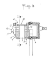
- the disc brake as shown in the accompanying drawings comprises a caliper 1 disposed astride a portion of the periphery of a brake disc 2 movable in rotation about an axis not shown.
- the stirrup 1 Near its two front and rear ends, the stirrup 1 is slidably mounted by means of two balusters 3,4 secured to a fixed support 5 in the corresponding bearings formed in the stirrup 1 so as to be able to slide parallel to the brake disc axis 2.
- Caliper 1 com carries a peripheral mounting opening 6 which is rectangular in shape and which is formed in the stirrup 1 to allow the passage of the active part of the outer 7 and inner friction pads 8.
- the inner pad 8 cooperates directly with a control motor 9 incorporated in the caliper 1 while the outer shoe cooperates indirectly with said motor 9 by pressing against the nose 10 of said caliper 1.
- Each friction pad 7 and 8 comprises on the side of the caliper 1 a lining plate 11, 12 made of a suitable metal and, on the side of the brake disc 2, a friction lining 13, 14 pressing against the corresponding side face of the brake disc 2 when the motor 9 is actuated.
- the front and rear sides of the passage opening 6 of the caliper 1 are delimited respectively by a guide edge 15 and 16 which extends parallel to the axis of the brake disc and which cooperates with one of the two support spouts 17, 18 or 19, 20 of the lining plate 11 or 12 of the outer shoe 7 or the inner shoe 8.
- the two friction pads 7 and 8 are arranged in the caliper 1 on either side of the brake disc 2 and are hung on the caliper by means of the end support spouts 17, 18 and 19, 20 conforming to the V shape of the guide edges 15 and 16. These pads 7 and 8 are locked against any radial displacement in the stirrup 1 by means of a locking key 22 inserted in the interval delimited by an edge of guide, for example 15, and the adjacent support spouts 17 and 19 of the pads 7 and 8, a pin 23 cooperating with the key 22 and the corresponding guide edge 15, to prevent any untimely movement of said key 22.
- the stirrup 1 is placed, by its front ends 24 and 25, without significant play, between a front stop 26 and a rear stop 27.
- These stops 26, 27 have the shape of a transverse bar s' extending parallel to the axis of the brake disc 2 above it over a length at least equal to the width of the space occupied by the two friction pads 7 and 8.
- Each of these stops 26, 27 is carried by a lateral arm 28, 29 secured to a fixed lateral support 30 provided on the inner sides of the brake disc 2.
- the fixed support 30 for the lateral support arms 28 and 29 of the stops 26 and 27 can be constituted by an independent fixed support or can be merged with the fixed support 5 in which the stirrup bars 3 and 4 are mounted. 1.
- the fixed support 30 and the fixed support 5 can be produced directly in the vehicle stub axle.
- the previously described embodiment may undergo a certain number of modifications without going beyond the protective framework defined by the appended modifications.
- the caliper by compression of said sleeves will systematically come into contact with the stops 26, 27 to fully transmit the braking torque to the fixed support 30, the columns in this case take practically no torque and are used only for sliding of the caliper as the friction elements 6 and 8 wear.
Landscapes
- Engineering & Computer Science (AREA)
- General Engineering & Computer Science (AREA)
- Mechanical Engineering (AREA)
- Braking Arrangements (AREA)
Claims (5)
Applications Claiming Priority (2)
| Application Number | Priority Date | Filing Date | Title |
|---|---|---|---|
| FR8300388 | 1983-01-12 | ||
| FR8300388A FR2539196B1 (fr) | 1983-01-12 | 1983-01-12 | Frein a disque |
Publications (2)
| Publication Number | Publication Date |
|---|---|
| EP0115980A1 EP0115980A1 (de) | 1984-08-15 |
| EP0115980B1 true EP0115980B1 (de) | 1986-05-14 |
Family
ID=9284862
Family Applications (1)
| Application Number | Title | Priority Date | Filing Date |
|---|---|---|---|
| EP84400065A Expired EP0115980B1 (de) | 1983-01-12 | 1984-01-12 | Scheibenbremse |
Country Status (8)
| Country | Link |
|---|---|
| US (1) | US4560036A (de) |
| EP (1) | EP0115980B1 (de) |
| JP (1) | JPH0733856B2 (de) |
| AU (1) | AU556489B2 (de) |
| DE (1) | DE3460129D1 (de) |
| ES (1) | ES284717Y (de) |
| FR (1) | FR2539196B1 (de) |
| YU (1) | YU984A (de) |
Families Citing this family (5)
| Publication number | Priority date | Publication date | Assignee | Title |
|---|---|---|---|---|
| DE4401843C2 (de) * | 1994-01-22 | 2003-04-30 | Continental Teves Ag & Co Ohg | Schwimmsattel für Scheibenbremse |
| DE19743538A1 (de) † | 1997-10-01 | 1999-04-08 | Wabco Perrot Bremsen Gmbh | Gleitsattel-Scheibenbremse |
| JP2002070898A (ja) * | 2000-09-01 | 2002-03-08 | Nisshinbo Ind Inc | ピンスライド型ディスクブレーキ装置 |
| US20050230197A1 (en) * | 2004-04-14 | 2005-10-20 | Jedele Philip N | One piece sliding brake caliper |
| US8973720B2 (en) * | 2012-08-17 | 2015-03-10 | Bendix Spicer Foundation Brake Llc | Disc brake pad mounting and retention system and method |
Family Cites Families (16)
| Publication number | Priority date | Publication date | Assignee | Title |
|---|---|---|---|---|
| FR1316440A (fr) * | 1962-03-02 | 1963-01-25 | Teves Kg Alfred | Frein à disque doté de garnitures de freinage partielles |
| US3917032A (en) * | 1974-02-11 | 1975-11-04 | Gen Motors Corp | Single mount and guide pin for a caliper of a disc brake assembly |
| CA1091599A (en) * | 1976-09-02 | 1980-12-16 | Donald D. Johannesen | Disc brake and mounting therefor |
| FR2378209A1 (fr) * | 1977-01-20 | 1978-08-18 | Dba | Frein a disque et pince elastique pour un tel frein |
| FR2409423A1 (fr) * | 1977-11-17 | 1979-06-15 | Dba | Frein a disque et clavette de guidage pour un tel frein |
| DE2757392A1 (de) * | 1977-12-22 | 1979-07-05 | Teves Gmbh Alfred | Teilbelagscheibenbremse |
| DE2807125C2 (de) * | 1978-02-20 | 1986-06-26 | Alfred Teves Gmbh, 6000 Frankfurt | Schwimmsattel-Teilbelagscheibenbremse, insbesondere für Kraftfahrzeuge |
| US4174769A (en) * | 1978-03-03 | 1979-11-20 | Societe Anonyme D.B.A. | Disc brake and a resilient clip for such a brake |
| US4274514A (en) * | 1978-08-28 | 1981-06-23 | The Bendix Corporation | Pin slider disc brake |
| DE2904118A1 (de) * | 1979-02-03 | 1980-09-04 | Teves Gmbh Alfred | Teilbelagscheibenbremse, insbesondere fuer kraftfahrzeuge |
| FR2470291A1 (fr) * | 1979-11-20 | 1981-05-29 | Dba | Frein a disque |
| JPS5686236U (de) * | 1979-12-06 | 1981-07-10 | ||
| US4310075A (en) * | 1980-03-10 | 1982-01-12 | The Bendix Corporation | Disc brake |
| JPS572937A (en) * | 1980-06-04 | 1982-01-08 | Matsushita Electric Ind Co Ltd | High frequency heating apparatus |
| JPS57156642U (de) * | 1981-03-30 | 1982-10-01 | ||
| FR2517399B1 (fr) * | 1981-11-30 | 1986-12-05 | Dba | Frein a disque et patin pour un tel frein |
-
1983
- 1983-01-12 FR FR8300388A patent/FR2539196B1/fr not_active Expired
- 1983-12-30 ES ES1983284717U patent/ES284717Y/es not_active Expired
-
1984
- 1984-01-05 US US06/568,478 patent/US4560036A/en not_active Expired - Fee Related
- 1984-01-05 YU YU00009/84A patent/YU984A/xx unknown
- 1984-01-10 AU AU23179/84A patent/AU556489B2/en not_active Expired
- 1984-01-12 JP JP59002783A patent/JPH0733856B2/ja not_active Expired - Lifetime
- 1984-01-12 EP EP84400065A patent/EP0115980B1/de not_active Expired
- 1984-01-12 DE DE8484400065T patent/DE3460129D1/de not_active Expired
Also Published As
| Publication number | Publication date |
|---|---|
| AU2317984A (en) | 1984-07-19 |
| FR2539196A1 (fr) | 1984-07-13 |
| ES284717Y (es) | 1986-04-01 |
| AU556489B2 (en) | 1986-11-06 |
| US4560036A (en) | 1985-12-24 |
| EP0115980A1 (de) | 1984-08-15 |
| YU984A (en) | 1988-04-30 |
| DE3460129D1 (en) | 1986-06-19 |
| ES284717U (es) | 1985-07-16 |
| FR2539196B1 (fr) | 1986-02-28 |
| JPH0733856B2 (ja) | 1995-04-12 |
| JPS59137629A (ja) | 1984-08-07 |
Similar Documents
| Publication | Publication Date | Title |
|---|---|---|
| EP0104108B2 (de) | Einarmschwinge für Antriebsräder | |
| EP0030502B1 (de) | Scheibenbremse | |
| FR2512904A1 (fr) | Frein a disque | |
| EP0772749B1 (de) | Bremsbelag und hiermit ausgerüstete scheibenbremse | |
| EP0366509B1 (de) | Bremse mit zwei Scheiben mit festem Abstand | |
| FR2548302A1 (fr) | Frein multidisque perfectionne | |
| EP0115980B1 (de) | Scheibenbremse | |
| EP0133389B1 (de) | Scheibenbremse mit abnehmbarem Verstärkungssattelarm | |
| EP0266262A2 (de) | Mehrscheibenbremse | |
| EP0059128A1 (de) | Niederhaltefeder für Scheibenbremsen | |
| EP1451482B1 (de) | Scheibenbremssattel für fahrzeuge | |
| EP1064471B1 (de) | Durch querkraft gedämpfte scheibenbremse | |
| EP0117192B1 (de) | Scheibenbremse | |
| EP0054496B1 (de) | Verriegelungselement für eine Schwimmsattel-Scheibenbremse und ein derartiges Verriegelungselement aufweisende Scheibenbremse | |
| EP0966620B1 (de) | Hybrides mehrscheibenbremssystem | |
| EP0830519A1 (de) | Scheibenbremse mit rotatorisch vorgespanntem bremssschuh | |
| FR2549182A1 (fr) | Dispositif de commande de frein a disque pour vehicules automobiles ou remorques | |
| FR2578931A1 (fr) | Frein a disque a etrier coulissant | |
| EP0118337B1 (de) | Scheibenbremse | |
| EP0114549B1 (de) | Scheibenbremse | |
| EP0648316B1 (de) | Verbindungsvorrichtung mit elastischerrückstellung | |
| FR2965027A1 (fr) | Frein a disque a etrier flottant pour vehicule automobile | |
| EP2861479B1 (de) | Aussermittiges joch für ein kraftfahrzeuglenksystem | |
| EP0645551A1 (de) | Schwimmsattel-Scheibenbremse | |
| EP0120738B1 (de) | Scheibenbremse mit verschiebbarem Sattel |
Legal Events
| Date | Code | Title | Description |
|---|---|---|---|
| PUAI | Public reference made under article 153(3) epc to a published international application that has entered the european phase |
Free format text: ORIGINAL CODE: 0009012 |
|
| 17P | Request for examination filed |
Effective date: 19840123 |
|
| AK | Designated contracting states |
Designated state(s): DE GB IT SE |
|
| RAP1 | Party data changed (applicant data changed or rights of an application transferred) |
Owner name: BENDIX FRANCE |
|
| ITF | It: translation for a ep patent filed | ||
| GRAA | (expected) grant |
Free format text: ORIGINAL CODE: 0009210 |
|
| RAP1 | Party data changed (applicant data changed or rights of an application transferred) |
Owner name: BENDIX FRANCE |
|
| AK | Designated contracting states |
Kind code of ref document: B1 Designated state(s): DE GB IT SE |
|
| REF | Corresponds to: |
Ref document number: 3460129 Country of ref document: DE Date of ref document: 19860619 |
|
| PLBE | No opposition filed within time limit |
Free format text: ORIGINAL CODE: 0009261 |
|
| STAA | Information on the status of an ep patent application or granted ep patent |
Free format text: STATUS: NO OPPOSITION FILED WITHIN TIME LIMIT |
|
| 26N | No opposition filed | ||
| ITTA | It: last paid annual fee | ||
| EAL | Se: european patent in force in sweden |
Ref document number: 84400065.3 |
|
| REG | Reference to a national code |
Ref country code: GB Ref legal event code: IF02 |
|
| PGFP | Annual fee paid to national office [announced via postgrant information from national office to epo] |
Ref country code: GB Payment date: 20021218 Year of fee payment: 20 |
|
| PGFP | Annual fee paid to national office [announced via postgrant information from national office to epo] |
Ref country code: SE Payment date: 20030123 Year of fee payment: 20 |
|
| PGFP | Annual fee paid to national office [announced via postgrant information from national office to epo] |
Ref country code: DE Payment date: 20030225 Year of fee payment: 20 |
|
| PG25 | Lapsed in a contracting state [announced via postgrant information from national office to epo] |
Ref country code: GB Free format text: LAPSE BECAUSE OF EXPIRATION OF PROTECTION Effective date: 20040111 |
|
| REG | Reference to a national code |
Ref country code: GB Ref legal event code: PE20 |
|
| EUG | Se: european patent has lapsed |